

Page 1
4043H_Manuals 10/29/10 9:31 AM Page 1
Self-Leveling Two or Three-Beam Laser Dot
Model No. 40-6670 & 40-6675
Instruction Manual
Congratulations on your choice of this Self-Leveling Two or Three-Beam
Laser Dot. We suggest you read this instruction manual thoroughly
before using the instrument. Save this instruction manual for future use.
This tool emits two or three laser beams, which projects a series of
visible points on surfaces around the product 40-6675 (front, up and
down) and 40-6670 (up and down). Beam visibility depends upon
lighting conditions in the work area.
This is a Class IIIa laser tool and is manufactured to comply with CFR 21,
parts 1040 .10 and 1040 .11 as well as international safety rule IEC 285.
©2010 Johnson Level & Tool - Rev. 1 1
Page 2
4043H_Manuals 10/29/10 9:31 AM Page 2
Table of Contents
1. Kit Contents
2. Features and Functions
3. Safety Instructions
4. Location/Content
of Warning Labels
5. Location of Parts/Components
6. Operating Instructions
7. Self-Check & Fine Calibration
8. Technical Specifications
9. Application Demonstrations
10. Care and Handling
11. Product Warranty
12. Warranty Registration
13. Accessories
1. Kit Contents
Description Qty.
Self-leveling Two or Three-Beam Laser Dot 1
“AA” Alkaline Batteries 3
Magnetic Target 1
Instruction Manual with Warranty Card 1
Soft Sided Pouch 1
2. Features and Functions
• Product simultaneously projects two or three laser beams 40-6675
(front, up and down) and 40-6670 (up and down).
• Magnetic dampening compensation system.
• Maintains level even when effected by vibration on the job site.
• Laser flashes and sounds audible alarm when product is
beyond leveling range.
• Low voltage indication with power indication lamp flashing.
• Pendulum locking mechanism helps protect units inner
mechanisms.
• Dust and rain resistant.
2 ©2010 Johnson Level & Tool - Rev. 1
Page 3
4043H_Manuals 10/29/10 9:31 AM Page 3
3. Safety Instructions
Please read and understand all of the following instructions, prior
to using this tool. Failure to do so, may void the warranty.
ATTENTION IMPORTANT
• Read all instructions prior to operating this laser tool. Do not remove any labels from tool.
• Do not stare directly at the laser beam.
• Do not project the laser beam directly into the eyes of others.
• Do not set up laser tool at eye level or operate the tool near a reflective surface as
the laser beam could be projected into your eyes or into the eyes of others.
• Do not place the laser tool in a manner that may cause someone to unintentionally
look into the laser beam. Serious eye injury may result.
• Do not operate the tool in explosive environments, i.e. in the presence of gases or
flammable liquids.
• Keep the laser tool out of the reach of children and other untrained persons.
• Do not attempt to view the laser beam through optical tools such as telescopes as
serious eye injury may result.
• Always turn the laser tool off when not in use or left unattended for a period of time.
• Remove the batteries when storing the tool for an extended time (more than 3 months)
to avoid damage to the tool should the batteries deteriorate.
• Do not attempt to repair or disassemble the laser tool. If unqualified persons attempt
to repair this tool, warranty will be void.
• Use only original Johnson
authorized dealer. Use of non-Johnson®parts and accessories will void warranty.
®
parts and accessories purchased from your Johnson
®
©2010 Johnson Level & Tool - Rev. 1 3
Page 4
4043H_Manuals 10/29/10 9:31 AM Page 4
CAUTION!
Class IIIa Laser Product
Max. Power Output: ≤ 5mW
Wavelength: 625-645nm
THIS TOOL EMITS LASER RADIATION.
DO NOT STARE INTO BEAM.
AVOID DIRECT EYE EXPOSURE.
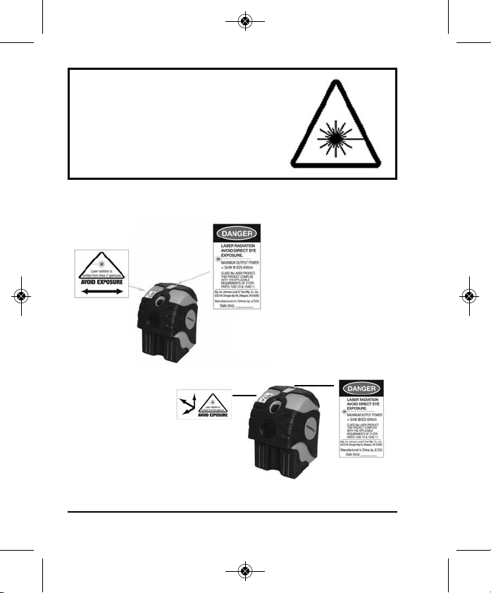
4. Location/Content of Warning Labels
40-6670
40-6675
4 ©2010 Johnson Level & Tool - Rev. 1
Page 5
4043H_Manuals 10/29/10 9:31 AM Page 5
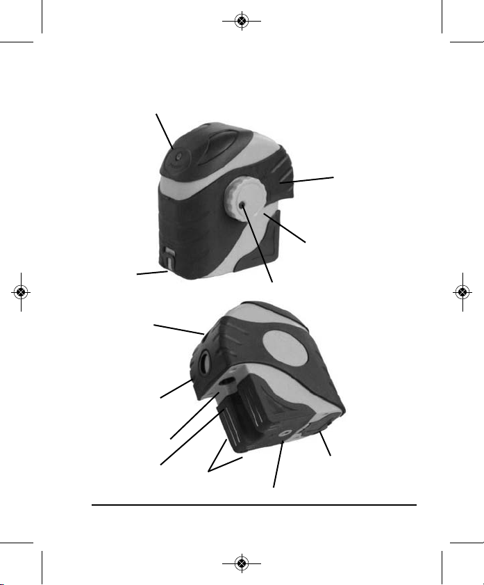
5. Location of Part/Components
Power LED
Battery
door/lock
Laser output
window
Laser output
window
(40-6675 only)
Laser output
window
Calibration port
plug
©2010 Johnson Level & Tool - Rev. 1 5
Magnets
1/4” screw thread hole
On/Off Indicator
Compensator lock
and On/Off Switch
Calibration port plug
Battery door
Page 6

4043H_Manuals 10/29/10 9:31 AM Page 6
6. Operating Instructions
IMPORTANT: It is the responsibility of the user to verify the
calibration of the instrument before each use.
Alkaline Battery Installation
Note: Always check to be sure that the on/off switch is in the off
position before removing and replacing batteries.
1. As shown in figure, put 3”AA” alkaline batteries into the battery
compartment noting the polarity as shown in the battery
compartment. Snap the battery cover shut. Turn the on/off
switch to on. If the power LED is flashing, the battery is low.
6 ©2010 Johnson Level & Tool - Rev. 1
Page 7

4043H_Manuals 10/29/10 9:31 AM Page 7
Using the Instrument
Power on/off
Turn the compensator lock on/off switch in the direction indicated by
the arrow.
To unlock and turn laser on. To lock and turn laser off.
Note: Product must be within ± 3° of level for self-leveling feature
to function properly. Greater than ± 3° will result in an alarm
condition (flashing laser and intermittent beeping sound).
Output of laser line:
40-6670
©2010 Johnson Level & Tool - Rev. 1 7
40-6675
Page 8

4043H_Manuals 10/29/10 9:31 AM Page 8
7. Self-Check & Fine Calibration
IMPORTANT: It is the responsibility of the user to verify the
calibration of the instrument before each use.
Figure 1
1-1
E
1-3
1-2
1-4
Accuracy Self-Check - Plumb point accuracy self-check
1. As shown in figure 1, put the unit on the ground in the direction shown in
figure 1-1.
2. Power on the unit and mark the center of plumb-down as point “E” and
plumb-up point as “A”.
3. Turn the unit 90° (as shown in figure 1-2) and place the down beam on
the “E” mark. Mark the center of the plumb-up point as “B”.
4. Turn the unit 90°again (as shown in figure 1-3) and repeat step 3. Mark
the center of the plumb-up point as “C”.
5. Turn the unit 90°again (as shown in figure 1-4) and repeat step 3. Mark
the center of the plumb-up point as “D”.
6. Marks A-D should all be in the same spot. If not, the unit will need to be
recalibrated. Please see calibration adjustment information.
8 ©2010 Johnson Level & Tool - Rev. 1
Page 9

4043H_Manuals 10/29/10 9:31 AM Page 9
Accuracy Self-Check - Horizontal Laser (40-6675 only)
1. Set the instrument on a level surface such as a flat head tripod
centered between two walls (marked 1 & 2) approximately 25 feet
apart. (See fig. 1).
2. Point the instrument directly at wall 1. Turn the laser on and mark the the
beam as point A.
3. Turn the instrument 180 degrees so that the laser is pointed directly at wall
2. Turn the laser and mark the beam as point B.
4. Move the instrument and the tripod so the laser is positioned approximately
2 feet away from wall 1 (see fig. 2). Level the tripod and position the
instrument on the tripod facing wall 1. Turn the laser on and mark the the
beam as point C.
5. Turn the laser off and rotate the laser 180 degrees so that it is
facing directly to wall 2.
6. Turn on the laser and mark the beam
as point D.
7. Measure the distance between
points A & C.
8. Measure the distance between
points B & D.
9. If the difference between points
A & C and points B & D are less
than 1/16”, your instrument is within
its tolerance.
10. If it is greater than 1/16”, your unit
will need to be recalibrated.
Wall 1
25 ft.
(7.6m)
Fig 2
48 ft.
(14.6m)
25 ft.
(7.6m)
Wall 2
Fig 1
©2010 Johnson Level & Tool - Rev. 1 9
Page 10

4043H_Manuals 10/29/10 9:31 AM Page 10
Calibration
1. Locate the front and side calibration port rubber plugs.
2. Carefully remove the rubber plugs.
3. Compensator must be unlocked and power on before making
calibration adjustments.
4. Use a 3mm Allen wrench.
5. For adjustment to the level/front beam, turn the Front A calibration screw
clockwise to raise the beam and counter-clockwise to lower the beam.
(40-6675 only)
6. For adjustment to the plumb beam, turn the Side B calibration screw
clockwise to move the plumb beam away from you and counter-clockwise
to move the beam toward you.
10 ©2010 Johnson Level & Tool - Rev. 1
Page 11

4043H_Manuals 10/29/10 9:31 AM Page 11
8. Technical Specifications
Laser Wavelength 635nm±10
Laser Classification Class IIIa
Maximum Power Output ≤5mW
Accuracy ±1/8"/50 ft. (±2mm/10m)
Interior Range Up to 100 ft. (30m) depending
Self-Leveling Range ± 3°
Power Supply 3 “AA” alkaline batteries (included)
Battery Life Approx. battery life 50 hours continuous use
Dimensions 4.212” x 2.598” x 4.528”
Weight 0.127lbs. (0.58 Kg)
Working Temperature 14°F to 113°F (-10°C to +45°C)
Center Screw Thread 1/4” - 20
IP Protection Class 54
©2010 Johnson Level & Tool - Rev. 1 11
upon light conditions
(107 x 66 x 115mm)
Page 12

4043H_Manuals 10/29/10 9:31 AM Page 12
9. Application Demonstrations
Plumb reference for lamp installation
Reference for pipeline installation
Reference for door frame installation
Reference for vertical partition
12 ©2010 Johnson Level & Tool - Rev. 1
Reference for fence installation
Reference for dormer installation
Reference for construction cubic partition
Page 13

4043H_Manuals 10/29/10 9:31 AM Page 13
10. Care and Handling
• This laser unit is a precision tool that must be handled with care.
• Avoid exposing unit to shock vibrations and extreme temperatures.
• Before moving or transporting the unit, make sure that the unit is turned off.
• Remove the batteries when storing the unit for an extended time (more than
three months) to avoid damage to the unit should the batteries deteriorate.
• Always store the unit in its case when not in use.
• Avoid getting the unit wet.
• Keep the laser unit dry and clean, especially the laser output window.
Remove any moisture or dirt with a soft, dry cloth.
• Do not use harsh chemicals, strong detergents or cleaning solvents to clean
the laser unit.
11. Product Warranty
Johnson Level & Tool offers a three year limited warranty on each of its products.
You can obtain a copy of the limited warranty for a Johnson Level & Tool
product by contacting Johnson Level & Tool's Customer Service Department,
as provided below, or by visiting our web site at www.johnsonlevel.com. The
limited warranty for each product contains various limitations and exclusions.
Do not return this product to the store/retailer or place of purchase.
Non-warranty repairs and course calibration must be done by an authorized
Johnson®service center or Johnson Level & Tool's limited warranty, if
applicable, will be void and there will be NO WARRANTY. Contact one of our
service centers for all non-warranty repairs. A list of service centers can be
found on our web site at www.johnsonlevel.com or by calling our Customer
Service Department. Contact our Customer Service Department for Return
Material Authorization (RMA) for warranty repairs (manufacturing defects
only). Proof of purchase is required.
©2010 Johnson Level & Tool - Rev. 1 13
Page 14

4043H_Manuals 10/29/10 9:31 AM Page 14
NOTE: The user is responsible for the proper use and care of the product. It is the
responsibility of the user to verify the calibration of the instrument before each use.
For further assistance, or if you experience problems with this product that are not
addressed in this instruction manual, please contact our Customer Service Dept.
In the U.S., contact Johnson Level & Tool’s Customer Service Department at
888-9-LEVELS.
In Canada, contact Johnson Level & Tool’s Customer Service Department at
800-346-6682.
13. Warranty Registration
Enclosed with this instruction manual you will find a warranty
registration card to be completed for your product. You will need to
locate the serial number for your product that is located on the bottom
of the unit. PLEASE NOTE THAT IN ADDITION TO ANY OTHER
LIMITATIONS OR CONDITIONS OF JOHNSON LEVEL & TOOL'S
LIMITED WARRANTY, JOHNSON LEVEL & TOOL MUST HAVE
RECEIVED YOUR PROPERLY COMPLETED WARRANTY CARD AND
PROOF OF PURCHASE WITHIN 30 DAYS OF YOUR PURCHASE OF
THE PRODUCT OR ANY LIMITED WARRANTY THAT MAY APPLY
SHALL NOT APPLY AND THERE SHALL BE NO WARRANTY.
14 ©2010 Johnson Level & Tool - Rev. 1
Page 15

4043H_Manuals 10/29/10 9:31 AM Page 15
13. Accessories
Johnson®accessories are available for purchase through authorized
®
Johnson
applicable limited warranty and there will be NO WARRANTY. If you need
any assistance in locating any accessories, please contact our
Customer Service Department.
In the U.S., contact Johnson Level & Tool’s Customer Service
Department at 888-9-LEVELS.
In Canada, contact Johnson Level & Tool’s Customer Service
Department at 800-346-6682.
dealers. Use of non-Johnson®accessories will void any
©2010 Johnson Level & Tool - Rev. 1 15
Page 16

4043H_Manuals 10/29/10 9:31 AM Page 16
16 ©2010 Johnson Level & Tool - Rev. 1
 Loading...