

Page 1
Multi-Beam Self-Leveling Line Generator
™
Model No. 40-6660
Instruction Manual
Congratulations on your choice of this Multi-Beam Self-Leveling Line
Generator. We suggest you read this instruction manual thoroughly
before using the instrument. Save this instruction manual for future use.
This tool emits five laser beams and one down plumb beam which
projects a series of visible points on surfaces around the product (i.e.
left, right, front, up, and down). Beam visibility depends upon lighting
conditions in the work area.
This is a Class IIIa laser tool and is manufactured to comply with CFR 21,
parts 1040 .10 and 1040 .11 as well as international safety rule IEC 285.
©2007 Johnson Level & Tool v.2 1
Page 2

Table of Contents
1. Kit Contents
2. Features and Functions
3. Safety Instructions
4. Location/Content
of Warning Labels
5. Location of Parts/Components
6. Operating Instructions
7. Using the Accessories
8. Self-Check and Calibration
9. Technical Specifications
10. Application Demonstrations
11. Care and Handling
12. Product Warranty
13. Product Registration
14. Accessories
1. Kit Contents
Description Qty.
Multi-Beam Self-Leveling Line Generator 1
Base 1
Ni-MH Rechargeable Battery Pack 2
5/8" –11 Tripod Adapter 1
Spanner Wrench for Tripod Adapter 1
Battery Adapter 1
Detector with Clamp and 9V Battery 1
Tinted Glasses 1
Magnetic Target 1
Instruction Manual with Warranty Card 1
Hard Shell Carrying Case 1
2 ©2007 Johnson Level & Tool
Page 3

2. Features and Functions
• Switchable between continuous laser state and pulse laser beam
(for use with detector)
• Able to project four laser cross lines and one laser point
(and a down plumb)
• Self-leveling compensation system.
• Laser flashes and sounds audible alarm when product beyond
leveling range.
• Able to individually project one horizontal line, or three vertical
lines that are perpendicular to each other, with one red plumbdown point.
• Able to simultaneously emit three cross lines in right angle,
and one plumb beam formed by cross intersection on ceiling,
and plumb-down point.
• The top vial can help to ensure higher accuracy.
• Able to freely rotate by 360 degrees, and allows for fine angle
adjustment.
• Unique base is foldable, and its legs are adjustable in length.
• Plumb-down point can be shift and centered.
• Magnetic dampening compensation system.
• Can be connected with tripod through 5/8" screw fittings.
• The included laser detector provides added functionability by
allowing use of the unit (in pulse setting) outdoors or in bright
surroundings where beams are not visible.
3. Safety Instructions
Please read and understand all of the following instructions, prior
to using this tool. Failure to do so, may result in bodily injury.
©2007 Johnson Level & Tool 3
Page 4
DANGER!
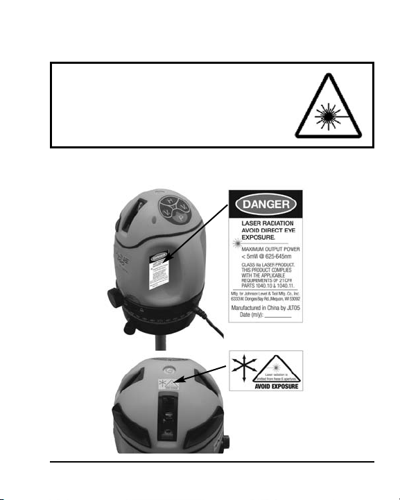
Class IIIa Laser Product
Max. Power Output: ≤ 5mW
Wavelength: 625-645nm
THIS TOOL EMITS LASER RADIATION.
DO NOT STARE INTO BEAM.
AVOID DIRECT EYE EXPOSURE.
ATTENTION IMPORTANT
• Read all instructions prior to operating this laser tool. Do not remove any labels from
tool.
• Use of controls or performance of procedures other than those specified herein may
result in hazardous radiation exposure.
• Do not stare directly at the laser beam.
• Do not project the laser beam directly into the eyes of others.
• Do not set up laser tool at eye level or operate the tool near a reflective surface as
the laser beam could be projected into your eyes or into the eyes of others.
• Do not place the laser tool in a manner that may cause someone to unintentionally
look into the laser beam. Serious eye injury may result.
• Do not operate the tool in explosive environments, i.e. in the presence of gases or
flammable liquids.
• Keep the laser tool out of the reach of children and other untrained persons.
• Do not attempt to view the laser beam through optical tools such as telescopes as
serious eye injury may result.
• Always turn the laser tool off when not in use or left unattended for a period of time.
• Remove the batteries when storing the tool for an extended time (more than 3 months)
to avoid damage to the tool should the batteries deteriorate.
• Do not attempt to repair or disassemble the laser tool. If unqualified persons attempt
to repair this tool, serious injury may result.
• Use only original AccuLine Pro
Pro authorized dealer. Use of non-AccuLine Pro parts and accessories will void warranty.
™
parts and accessories purchased from your AccuLine
4 ©2007 Johnson Level & Tool
Page 5
CAUTION: If using this product with any type of tinted goggles,
please note safety warning below.
WARNING!
The tinted goggles are designed to enhance
the visibility of the laser beam. They DO NOT
offer protection to the eyes from direct exposure
of the laser beam.
4. Location/Content of Warning Labels
©2007 Johnson Level & Tool 5
Page 6
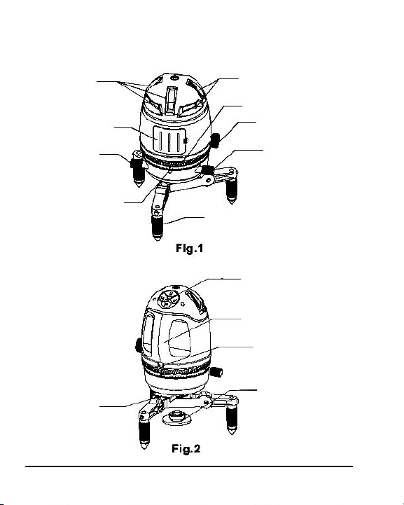
5. Location of Part/Components
Laser Output
Window
Battery Box
Fine Adjusting
Screw
Angle Dial
Indication
Locking Staff
6 ©2007 Johnson Level & Tool
Laser Output
Window
Angle Dial
Locking Knob
Fine Adjusting
Screw
Tripodic Base
Operating Panel
Handle
DC Outlet
Connecting
Board
Page 7

6. Operating Instructions
IMPORTANT: It is the responsibility of the user to verify the calibration
of the instrument before each use.
Battery Installation
Note: Always check to be sure that the on/off switch is in the off
position before removing and replacing batteries.
1. Open the battery box and put in rechargeable battery pack.
Please pay attention to polarity.
2. Indicator lamp blinking means low voltage. Charge the rechargeable
battery pack before initial use.
Note:
• As for the initial two times charge of new battery pack, it is
necessary to charge for 12-plus hours.
• Do not charge alkaline batteries to avoid explosion.
• Used (discharged) batteries are hazardous waste and should be
disposed of properly.
DC Outlet
1. Connect adapter (included) to the outlet.
2. You don't need to take out the battery pack when using the
adapter.
Power-On
1. By setting the locking knob to UNLOCK
position, the self-leveling system is
released, and simultaneously the
instrument is powered on.
©2007 Johnson Level & Tool 7
Unlocking Position
Page 8

2. Activate the horizontal line H, vertical lines V1 and V2, and plumbdown point by pressing the corresponding keys on the operating
panel (Fig. 3).
1. Horizontal Line H Button
2. Vertical Line V1Button
3. Modulation Switching P Button
4. Power Indicator Lamp
5. Vertical Line V2 Button
6. Modulation Switching Indicator Lamp
3. When the power indicator lamp is lit, this means the laser is
turned on. When the blinking power indicator lamp is lit, this
means low battery voltage.
4. If the instrument is set up on a slope beyond the self-leveling
range, the laser will flash and with an audible sound at the same
time. Users should reset up the instrument to a more level position (with the aid of the vial on top).
5. When the horizontal line H, vertical line V1 and V2 are all lit,
these three laser lines form four cross intersections.
Among them, the top intersection
is the plumb-up point of the unit,
which constitutes plumb beam
together with the plumb-down
point. Three intersections on the
horizontal line is the horizontal
cross lines perpendicular to each
other (Fig. 4).
Horizontal
cross
V2
Plumb-down
Point
V2
Top cross
V1
H
Horizontal
V2
cross
H
Fig. 4
8 ©2007 Johnson Level & Tool
Page 9

6. Adjust the screws on the three legs of
the base to center the top bubble, which
will achieve the higher accuracy (Fig. 5).
Power-Off
Set the locking knob to LOCK position, and
Bubble
Centering
Screw
the instrument is powered off (Fig. 6).
Fig. 5
Fig. 6
Locking Position
Note: The locking knob must be set to LOCK position when the user
needs to move the instrument or packed into the case. If the alarms
sounds when you move the unit, it means the locking screw is not
locked. Please make sure to lock it.
Center Position Adjusting
Fig. 7
Locking Staff
Push the locking staff leftwards, and then
the instrument can be moved to different
directions freely in order to have plumb-down
laser point accurately coincide with the
Unlocking Locking
reference mark on floor. Push the locking staff
rightwards, and then you can't move the instrument any more (Fig. 7).
Laser Output Position Adjusting
Rotate the instrument to the desired position,
Fine
Adjusting
Screw
and then adjust the two fine adjusting screws
for precise angle adjustment (Fig. 8).
Fig. 8
©2007 Johnson Level & Tool 9
Page 10

Angle Dial
The angle dial is helpful when users need to
set the instrument to a desired angle. Have
Fine
Adjusting
Screw
the vertical lines aim at an object, and then
rotate the angle dial to make the zero scale
Fig. 8
coincide with the angle dial scale.
Then adjust the instrument to the
desired angle according to the
method described in Laser Output
Position Adjusting (Fig. 8, Fig. 9).
Fig. 9 Angle Dial
Angle Dial
Indication
7. Using the Accessories
Laser Detector Usage
With the laser detector included, the instrument can be used both
indoors with bright light and/or outdoors in the sunlight where beams
are not visible.
1. Horizontal Indicating Bubble
2. Detecting Window
3. Sound Option Key
4. Power On/Off Key
5. Vertical Indicating Bubble
6. LCD
7. 0 Scale
8. Buzzer
10 ©2007 Johnson Level & Tool
9. Upper Indicator Lamp
10. Middle Indicator Lamp
11. Lower Indicator Lamp
12. Lineation Groove
13. Set Screw
14. Battery Door
Page 11

LCD Indicating Note
1. Power
2. Low Voltage
3. Detection
4. Sound
5. Detected Position
Operation Instruction
1. Battery Installation
Open the battery door, and put in one 9V battery
according to the polarity shown inside. Then
snap the battery door back.
Note:
• Take the battery out when the unit is not in use for a long time.
• Replace the battery when indicator shows low battery.
• Used (discharged) batteries are hazardous waste and should be
disposed of properly
2. Detection
(Important: The detector will only work in pulse mode)
Note: Keep the unit stable during detection.
A. One press on Power on/off key will show
all signs on LCD, and 0.5 second later the
detector enters detecting status, with
only Power-on and detection signs shown
on LCD.
©2007 Johnson Level & Tool 11
Page 12

B. Detecting the horizontal laser signal:
Put the detector in a vertical position
(observe the horizontal indicating bubble)
with the detecting window facing the
unit to receive the laser signal. A downward arrow shown on LCD plus a lit red lamp means the laser
signal is below the detector. An Upward arrow plus a yellow lit
lamp means the laser signal is above the detector. A middle sign
plus a lit green lamp means the laser signal is centered.
Note: When the laser signal moves towards
the center position, the displayed upward
or downward arrows will decrease segment
by segment along the direction towards the
middle, until the centered single line appears.
C. Detecting the vertical laser signal. Put the detector
in a horizontal position (observe the vertical indicating bubble) with the face including an indicator lamp upwards. Have the detecting window
face the unit to receive the vertical laser signal.
Leftward arrow shown on LCD plus a lit red lamp
means the laser signal is on the left side. A v centered sign with a lit green lamp means the laser
signal is on the middle position. A rightward arrow
plus a lit yellow lamp means the laser signal is on the right side.
D. Press the Power on/off key in the power-on state, and the
detector will be powered off.
12 ©2007 Johnson Level & Tool
Page 13

3. Sound Function
Pressing the sound key under power-on
status will switch the unit between
sound status and silent status, with the
Sound
Silence
sound sign indication on LCD.
Under the status with sound function on:
• If the laser signal is on the top (left) side, then the detector will
give single short alarm.
• If the laser signal is on the bottom (right) side, then the detector
will give double short alarm.
• If the laser signal is on the middle, then the detector will keep
long alarm.
Note: Whether under sound or silent status, the keys always keep
cue sound.
4. Power Save Function
When receiving no laser signal and no operation against keys for six
continuous minutes, the unit will power off automatically to preserve
battery life.
5. Low Battery Indicator Function
• When the power indicator sign is blinking,
this means that the battery is low and should
be replaced.
Blink
• Seriously low battery will result in automatic
power-off, which requires the user to
immediately replace before more operation.
©2007 Johnson Level & Tool 13
Page 14

Technical Specifications
Detecting Distance ≥164 ft (50m) 0
≥98 ft (30m) 45
Detecting Frequency 8KHz-12KHz
Detecting Accuracy 0.019" ≤ 49 ft. (0.5mm ≤15m)
0.039" ≤ 114 ft. (1mm ≤35m)
0.059" ≥ 114 ft. (1.5mm ≥35m)
Timed Power-off 6 minutes
Working Voltage DC 9V
Sound Function: Single short alarm
double short alarm
long alarm
LCD Upward arrow
downward arrow
centered sign
LED Indication Up, middle, down
Size 5.905" x 2.992" x 1.142" (150 x 76 x 29mm)
Weight 0.386 lb. (175g)
Dust and rain resistant
14 ©2007 Johnson Level & Tool
Page 15

Instrument Usage
Tripod Usage
The instrument can be used either directly on floor or on tripod. If operating
with tripod, users should first screw the connecting board into the thread
on the instrument bottom, and set it up on tripod
Tripodic Base Usage
1. Connect the instrument with tripodic base through 5/8” center thread,
and then the plumb-down point function become available for use.
2. Tripodic base can be folded used.
3. The legs could be adjusted in length
Laser Glasses Usage
1. Glasses are adjustable in leg length.
2. Red glasses can enhance the visibility laser beam. Glasses do not offer
protection to the eyes from direct exposure of the laser beam.
Laser Target Usage
1. The magnet on target can conveniently attached to metal objects.
2. Target can also be hung on wall or pillar.
3. Target can greatly increase the brightness of the observed laser beam.
©2007 Johnson Level & Tool 15
Page 16

8. Self-Check and Calibration
Horizontal Laser Line Accuracy Self-Check
1. Find a wall and set up the instrument at 16 ft. (5m) away from the wall.
2. Unlock the instrument and switch on the laser line H, V1, V2 by
pressing the button H, V1,V2.
3. Rotate the instrument
horizontally to have
V1 face against the
wall, and mark its
intersection with H
as point A (Fig. 11-1).
4. Turn the instrument
to have V2 coincide
Fig. 11-1
with point A.
5. Measure the distance e between H and point A.
6. If e >0.079" (2mm), the horizontal accuracy is beyond tolerance
(Fig. 11-2).
Vertical Laser Line Accuracy Self-Check
1. Find a wall and set up the unit at 16 ft. (5m) away from the wall.
2. Unlock the instrument and switch on the laser line V1 by pressing
the button V1.
3. Rotate the instrument horizontally to have V1 face against the
wall.
4. Hang up a plummet at the position of V1 as standard plumb line,
which is 9 ft. (3m) long and as close to the floor as possible.
5. Turn the fine adjusting knob to have the upside of V1 coincide
with the standard plumb line.
Fig. 11-2
16 ©2007 Johnson Level & Tool
Page 17

6. Observe whether the downside of V1
coincides with the standard plumb
line or not. If not, and the deviation
exceeds 0.039" (1mm), then V1
line's vertical accuracy e is beyond
tolerance (Fig.12).
Plummet
V
1
NOTE: During the observation, make
sure that your viewing is against the
laser line and the standard plumb line.
7. Follow the same method to check the accuracy of V2.
8. If the self-checked accuracy is beyond tolerance,
reference section 12 of this document.
9. Technical Specifications
Laser Wavelength 635nm±10nm
Laser Classification Class IIIa
Maximum Power Output ≤5mW
Accuracy ±3/8"/100 ft. (±3mm/10m)
Working Range Maximum 100 ft. (30m) depending upon
light conditions
Measuring Range 131 ft. (40m) radius with detector
Self-leveling Range ±3.5° with laser flashing and sound
alarm when out of tolerance
Power Supply Rechargeable battery pack or battery
adapter
Dimensions 5-1/2" x 5" x 7" (140 x 125 x 180mm)
Weight 9.39 lbs (4.25 Kg)
Working Temperature 14°F to 113°F (-10°C to +40° C)
Center Screw Thread 5/8" – 11; 1/4" –20
©2007 Johnson Level & Tool 17
Page 18

10. Application Demonstrations
Supply one super-long horizontal line
Supply 1 front vertical and 1 plumb
point
Supplyplumb reference formed bythe laser
crossline onceilingand plumbdownpoint
Simultaneouslysupply fourlasercrosslines
on the front,left,right,and top
Supply one super-long vertical line on ceiling
Supply 2 laser cross lines on right and left sides,
Supply one front laser cross line
Operate with one detector toextend
working distance
respectively
18 ©2007 Johnson Level & Tool
Page 19

11. Care and Handling
• This laser unit is a precision tool that must be handled with care.
• Avoid exposing unit to shock vibrations and extreme temperatures.
• Before moving or transporting the unit, make sure that the unit
is turned off and in the locked position. Failure to lock before
transport or storage may cause damage to the units inner
mechanism and void warranty.
• Remove the batteries when storing the unit for an extended time
(more than three months) to avoid damage to the unit should
the batteries deteriorate.
• Always store the unit in its case when not in use.
• Avoid getting the unit wet.
• Keep the laser unit dry and clean, especially the laser output
window. Remove any moisture or dirt with a soft, dry cloth.
• Do not use harsh chemicals, strong detergents or cleaning solvents
to clean the laser unit.
12. Product Warranty
Johnson Level & Tool offers a one year limited warranty on each its
products. You can obtain a copy of the limited warranty for a
Johnson Level & Tool product by contacting Johnson Level & Tool's
Customer Service Department as provided below or by visiting us
online at www.johnsonlevel.com. The limited warranty for each
product contains various limitations and exclusions.
Do not return this product to the store/retailer or place of purchase.
Required repair/calibration must be done by an authorized AccuLine
Pro™ service center or Johnson Level & Tool's limited warranty, if
applicable, will be void and there will be NO WARRANTY. Contact our
Customer Service Department to obtain a Return Material
©2007 Johnson Level & Tool 19
Page 20

Authorization (RMA) number for return to an authorized service center.
Proof of purchase is required.
NOTE: The user is responsible for the proper use and care of the
product.
It is the responsibility of the user to verify the calibration of the
instrument before each use.
For further assistance, or if you experience problems with this product
that are not addressed in this instruction manual, please contact our
Customer Service Department.
In the U.S., contact Johnson Level & Tool’s Customer Service
Department at 800-563-8553.
In Canada, contact Johnson Level & Tool’s Customer Service
Department at 800-346-6682.
13. Product Registration
Enclosed with this instruction manual you will find a warranty card to be
completed for product warranty registration. Product warranty registration
can also be completed online at our web site www.johnsonlevel.com.
You will need to locate the serial number for your product that is located
on the bottom of the unit. PLEASE NOTE THAT IN ADDITION TO ANY
OTHER LIMITATIONS OR CONDITIONS OF JOHNSON LEVEL &
TOOL'S LIMITED WARRANTY, JOHNSON LEVEL & TOOL MUST
HAVE RECEIVED YOUR PROPERLY COMPLETED WARRANTY CARD
WITHIN 30 DAYS OF YOUR PURCHASE OF THE PRODUCT OR ANY
LIMITED WARRANTY THAT MAY APPLY SHALL NOT APPLY AND
THERE SHALL BE NO WARRANTY.
20 ©2007 Johnson Level & Tool
Page 21

14. Accessories
AccuLine Pro™ accessories are available for purchase through
authorized AccuLine Pro dealers. Use of non-AccuLine Pro accessories
will void any applicable limited warranty and there will be NO WARRANTY.
If you need any assistance in locating any accessories, please contact
our Customer Service Department.
In the U.S., contact Johnson Level & Tool’s Customer Service
Department at 800-563-8553.
In Canada, contact Johnson Level & Tool’s Customer Service
Department at 800-346-6682.
©2007 Johnson Level & Tool 21
 Loading...