

Page 1
7048H_Manuals 6/19/13 10:53 AM Page 1
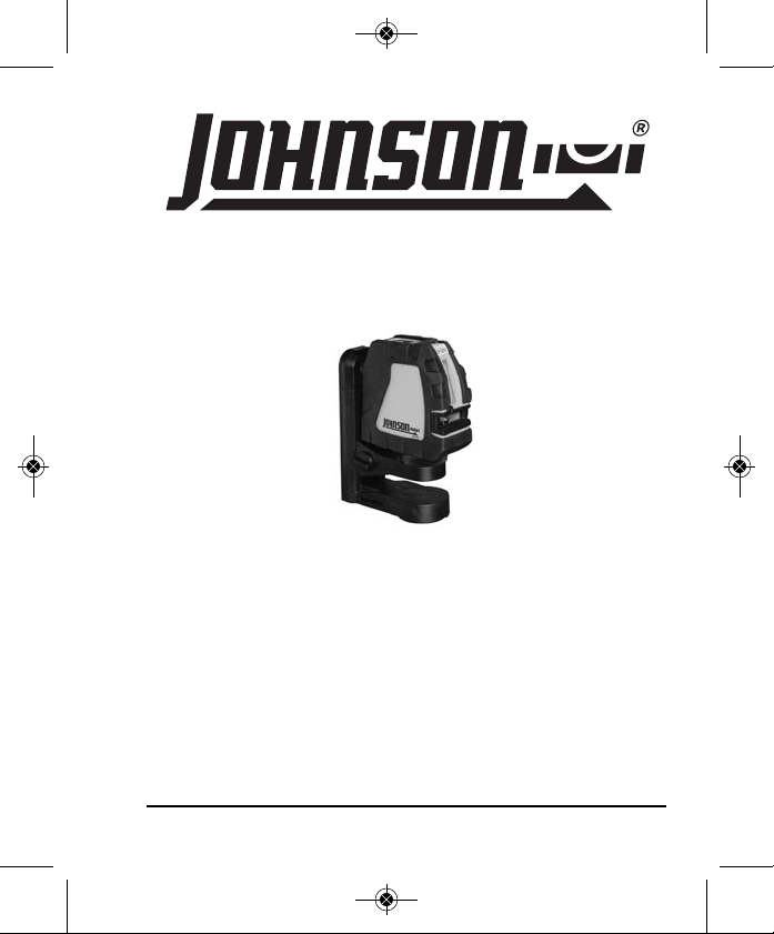
Self-Leveling Cross-Line Laser
Model Nos. 40-6650 & 40-6656
Instruction Manual
Congratulations on your choice of this Self-Leveling Cross-Line Laser.
We suggest you read this instruction manual thoroughly before using
the instrument. Save this instruction manual for future use.
This is a Class IIIa laser tool and is manufactured to comply with
CFR 21, parts 1040.10 and 1040.11 as well as international safety
rule IEC 285.
©2013 Johnson Level & Tool 1
Page 2
7048H_Manuals 6/19/13 10:53 AM Page 2
Table of Contents
1. Kit Contents
2. Features and Functions
3. Safety Instructions
4. Location/Content
of Warning Labels
5. Location of Parts/Components
6. Operating Instructions
7. Using the Product
8. Self-Check & Fine Calibration
9. Technical Specifications
10. Application Demonstrations
11. Care and Handling
12. Product Warranty
13. Warranty Registration
14. Accessories
1. Kit Contents
Description for Model 40-6650 & 40-6656 Qty.
Self-Leveling Cross-Line Laser Level 1
Multi-Functional Elevating Magnetic Bracket 1
“AA” Alkaline Batteries 3
Mounting Strap 1
Instruction Manual with Warranty Card 1
Soft-Sided Pouch 1
2. Features and Functions
• Able to project one horizontal, vertical or cross-line laser beam,
separately or simultaneously.
• Magnetic dampening compensation system.
• Self-leveling with a laser flash alarm when beyond leveling
range.
• Multi-functional elevating magnetic bracket is included to allow
the laser to hang on a wall, attach to metal, or connect to tripod
(5/8"-11 or 1/4"-20).
• Includes adjustable strap for attachment to pipe or conduit.
2 ©2013 Johnson Level & Tool
Page 3
7048H_Manuals 6/19/13 10:53 AM Page 3
3. Safety Instructions
Please read and understand all of the following instructions, prior
to using this tool. Failure to do so, may void the warranty.
ATTENTION
• Read all instructions prior to operating this laser tool. Do not remove any labels from tool.
• Do not stare directly at the laser beam.
• Do not project the laser beam directly into the eyes of others.
• Do not set up laser tool at eye level or operate the tool near a reflective surface as
the laser beam could be projected into your eyes or into the eyes of others.
• Do not place the laser tool in a manner that may cause someone to unintentionally
look into the laser beam. Serious eye injury may result.
• Do not operate the tool in explosive environments, i.e. in the presence of gases or
flammable liquids.
• Keep the laser tool out of the reach of children and other untrained persons.
• Do not attempt to view the laser beam through optical tools such as telescopes as
serious eye injury may result.
• Always turn the laser tool off when not in use or left unattended for a period of time.
• Remove the batteries when storing the tool for an extended time (more than 3 months)
to avoid damage to the tool should the batteries deteriorate.
• Do not attempt to repair or disassemble the laser tool. If unqualified persons attempt
to repair this tool, warranty will be void.
• Use only original Johnson
authorized dealer. Use of non-Johnson
©2013 Johnson Level & Tool 3
®
parts and accessories purchased from your Johnson
®
parts and accessories will void warranty.
IMPORTANT
®
Page 4
7048H_Manuals 6/19/13 10:53 AM Page 4
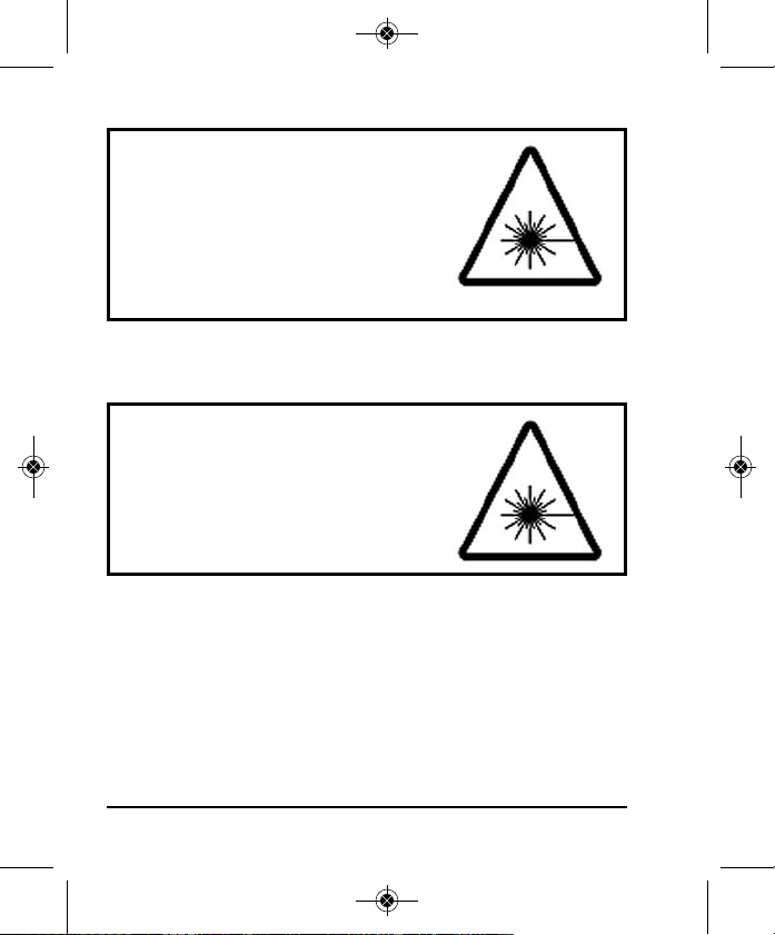
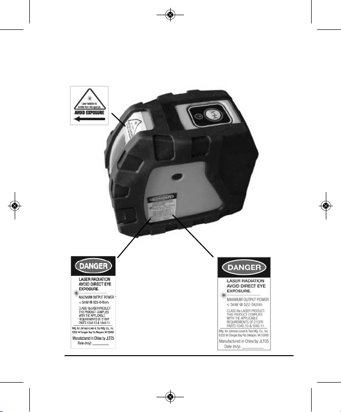
40-6650
DANGER!
Class IIIa Laser Product
Max. Power Output: ≤ 5mW
Wavelength: 625-645nm
THIS TOOL EMITS LASER RADIATION.
DO NOT STARE INTO BEAM.
AVOID DIRECT EYE EXPOSURE.
40-6656
DANGER!
Class IIIa Laser Product
Max. Power Output: ≤ 5mW
Wavelength: 522-542nm
THIS TOOL EMITS LASER RADIATION.
DO NOT STARE INTO BEAM.
AVOID DIRECT EYE EXPOSURE.
4 ©2013 Johnson Level & Tool
Page 5
7048H_Manuals 6/19/13 10:53 AM Page 5
4. Location/Content of Warning Labels
40-6650 40-6656
©2013 Johnson Level & Tool 5
Page 6
7048H_Manuals 6/19/13 10:53 AM Page 6
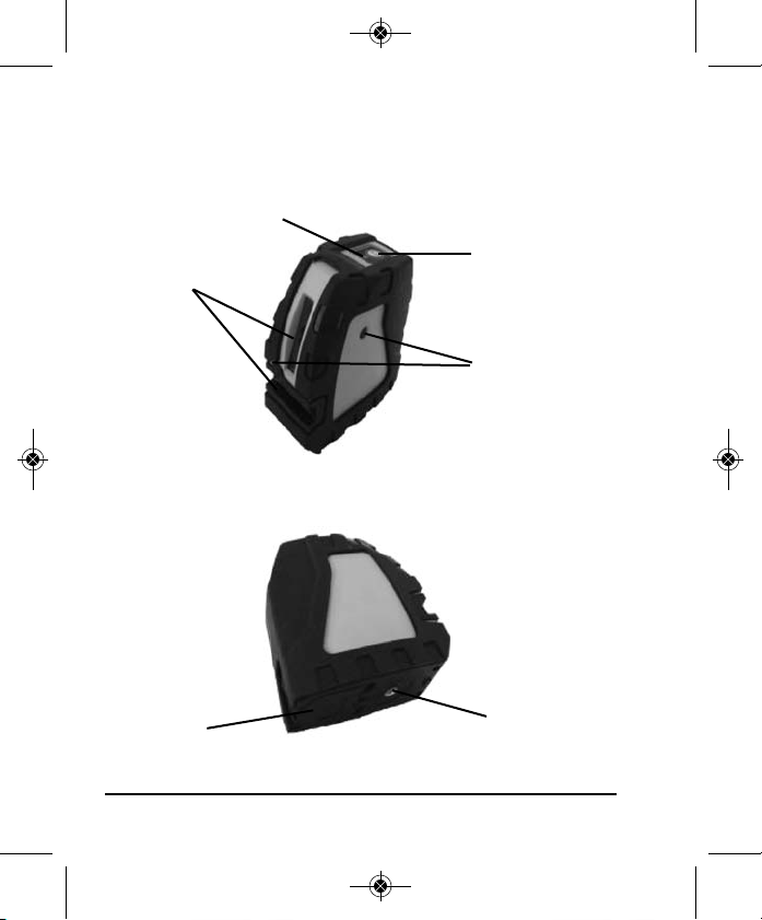
5. Location of Part/Components
Instrument
Power LED
Laser Output
Windows
Battery Cover
6 ©2013 Johnson Level & Tool
Laser Operation
Button
Self-Calibration
Aperture
1/4" Thread
Page 7

7048H_Manuals 6/19/13 10:53 AM Page 7
Multi-Functional Elevating Magnetic Bracket
Hang Hole
1/4" Thread
Laser
Attachment
Wheel
Lock/Unlock Knob
6. Operating Instructions
IMPORTANT: It is the responsibility of the user to verify the
calibration of the instrument before each use.
Battery Installation
Note: Always check to be sure that the power is off
before removing and replacing batteries.
1. Open the battery cover and put in three “AA”
batteries according to the illustrated polarity direction.
Note:
• Pay attention to the polarity of the batteries.
• Used (discharged) batteries are hazardous waste
and should be disposed of properly.
Belt Groove
Magnets
5/8" Thread
©2013 Johnson Level & Tool 7
Page 8

7048H_Manuals 6/19/13 10:53 AM Page 8
7. Using the Product
This bracket was specially designed for more extensive adaptability
of the laser. The bracket can be connected with a standard tripod by
5/8"-11 thread and a 1/4"-20 camera tripod. With the use of the
bracket, the laser can be freely rotated, hung on the wall, attached to a
metal plate, or bound on staff or pipe with use of its strap. Attach the
laser to the bracket using the laser attachment wheel on the bracket.
Operation Keypad
Power LED
Laser Operation Button
Power LED
ON (green): power is on
OFF: power is off
ON (red): low battery
Laser Operation Button
Press once for the vertical line only.
8 ©2013 Johnson Level & Tool
Page 9

7048H_Manuals 6/19/13 10:53 AM Page 9
Press a second time for the
horizontal line only.
Press a third time for both the
horizontal and vertical line
simultaneously.
Press a fourth time to turn both the horizontal and vertical
line off.
©2013 Johnson Level & Tool 9
Page 10

7048H_Manuals 6/19/13 10:53 AM Page 10
8. Self-Check & Fine Calibration
IMPORTANT: It is the responsibility of the user to verify the
calibration of the instrument before each use.
Horizontal Line Accuracy Self-Check (Transversely)
1. Set the instrument on a tripod and place approximately 5
Meters from a wall.
2. Unlock the unit and power the unit on.
3. Face the cross-line laser line to the wall, and set the center as
Dot ‘A’. Make a mark on the wall for Dot ‘A’. Make another
mark on the wall 2.5 Meters from Dot ‘A’ and mark on the wall
as Dot ‘M’.
4. Rotate the instrument 90° and make a mark on the wall 5
Meters from Dot ‘A’. Label this mark as Dot ‘B’.
10 ©2013 Johnson Level & Tool
Page 11

7048H_Manuals 6/19/13 10:53 AM Page 11
5. Measure the distance ‘e’ from Dot ‘M’ to the laser line, as per
the Figure.
6. If ‘e’ > 1.5mm, the instrument is out of tolerance and must be
calibrated.
Horizontal Accuracy Self-Check (Longitudinal)
1. Set up two survey-staffs, OR use two walls, both 5 Meters
from each other (or further).
2. Set the instrument on a level tripod, and center between the
two survey staffs/walls.
3. Power on all laser lines, and move the laser until the cross dot
projects on staff/wall A. Make a mark and label as ‘A1’.
4. Rotate the instrument 180° and make the cross dot project on
staff/wall B. Make a mark and label as ‘B1’.
©2013 Johnson Level & Tool 11
Page 12

7048H_Manuals 6/19/13 10:53 AM Page 12
5. Move the tripod so that the distance between the instrument
and staff/wall A is 0.6 Meters, and make the cross dot project
on staff/wall A. Make a mark and label as ‘A2’.
Less than 0.6 meters
6. Rotate the instrument by 180° and move the cross dot to project on staff/wall B. Make a mark and label as ‘B2’.
Less than 0.6 meters
7. Calculate (A1-A2) – (B1-B2) = e
8. If e> 1.5mm, the instrument is out of tolerance and must be
calibrated.
12 ©2013 Johnson Level & Tool
Page 13

7048H_Manuals 6/19/13 10:53 AM Page 13
Self-Calibration Adjustment
See the following figure. There are two self-calibration apertures on
the instrument. The self-calibration aperture A corresponds with the
adjustment of the fore/aft direction. The self-calibration aperture B
corresponds with the adjustment of the left/right direction.
1. When adjusting, use a 3mm hex tool.
2. The adjustment of both directions will influence each other.
When making fine adjustments in the left/right direction, it
might influence the front/back axis. Be sure to repeat the
adjustment of both axis when making adjustments to ensure
both are accurate.
3. When making adjustment with the adjusting screw, you should
not exceed four complete turns of the screw(s).
4. If the unit is still not able to be calibrated, it may be outside
of its adjustment range and should be sent to the nearest
service center.
©2013 Johnson Level & Tool 13
Page 14

7048H_Manuals 6/19/13 10:53 AM Page 14
9. Technical Specifications
Laser Wavelength 635nm±10 (40-6650)
532nm±10 (40-6656)
Laser Classification Class IIIa
Maximum Power Output ≤5mW
Accuracy ±1/8"/35 ft. (±3mm/10m)
Interior Range Up to 150 ft. (45m) depending upon light
conditions (40-6650)
Up to 200 ft. (60m) depending upon light
conditions (40-6656)
Self-Leveling Range ± 3°
Power Supply 3 “AA” alkaline batteries
Battery Life Approx. battery life 20 hours continuous use
Dimensions 4-1/8" x 1-15/16" x 4-1/8"
(104x49x104mm)
Weight 1.5 lbs. (0.3 Kg)
Working Temperature 14°F to 113°F (-10°C to +45°C)
Center Screw Thread 5/8" – 11; 1/4" – 20
IP Protection Class 55
14 ©2013 Johnson Level & Tool
Page 15

7048H_Manuals 6/19/13 10:53 AM Page 15
10. Application Demonstrations
Fixing cabinets
Fixing doors and windows
Installing partitions
Hanging pictures
©2013 Johnson Level & Tool 15
Laying tile
Setting pipelines
Installing baseboards
Dormer installation
Page 16

7048H_Manuals 6/19/13 10:53 AM Page 16
11. Care and Handling
• This laser unit is a precision tool that must be handled with care.
• Avoid exposing unit to shock vibrations and extreme temperatures.
• Before moving or transporting the unit, make sure that the unit is turned off.
• Remove the batteries when storing the unit for an extended time (more than
three months) to avoid damage to the unit should the batteries deteriorate.
• Always store the unit in its case when not in use.
• Avoid getting the unit wet.
• Keep the laser unit dry and clean, especially the laser output window.
Remove any moisture or dirt with a soft, dry cloth.
• Do not use harsh chemicals, strong detergents or cleaning solvents to clean
the laser unit.
12. Product Warranty
Johnson Level & Tool offers a three year limited warranty on each of its products.
You can obtain a copy of the limited warranty for a Johnson Level & Tool
product by contacting Johnson Level & Tool's Customer Service Department,
as provided below, or by visiting our web site at www.johnsonlevel.com. The
limited warranty for each product contains various limitations and exclusions.
Do not return this product to the store/retailer or place of purchase.
Non-warranty repairs and course calibration must be done by an authorized
Johnson®service center or Johnson Level & Tool's limited warranty, if
applicable, will be void and there will be NO WARRANTY. Contact one of our
service centers for all non-warranty repairs. A list of service centers can be
found on our web site at www.johnsonlevel.com or by calling our Customer
Service Department. Contact our Customer Service Department for Return
Material Authorization (RMA) for warranty repairs (manufacturing defects
only). Proof of purchase is required.
16 ©2013 Johnson Level & Tool
Page 17

7048H_Manuals 6/19/13 10:53 AM Page 17
NOTE: The user is responsible for the proper use and care of the product. It is the
responsibility of the user to verify the calibration of the instrument before each use.
For further assistance, or if you experience problems with this product that are not
addressed in this instruction manual, please contact our Customer Service Dept.
In the U.S., contact Johnson Level & Tool’s Customer Service Department at
888-9-LEVELS.
In Canada, contact Johnson Level & Tool’s Customer Service Department at
800-346-6682.
13. Warranty Registration
Enclosed with this instruction manual you will find a warranty
registration card to be completed for your product. You will need to
locate the serial number for your product that is located on the bottom
of the unit. PLEASE NOTE THAT IN ADDITION TO ANY OTHER
LIMITATIONS OR CONDITIONS OF JOHNSON LEVEL & TOOL'S
LIMITED WARRANTY, JOHNSON LEVEL & TOOL MUST HAVE
RECEIVED YOUR PROPERLY COMPLETED WARRANTY CARD AND
PROOF OF PURCHASE WITHIN 30 DAYS OF YOUR PURCHASE OF
THE PRODUCT OR ANY LIMITED WARRANTY THAT MAY APPLY
SHALL NOT APPLY AND THERE SHALL BE NO WARRANTY.
©2013 Johnson Level & Tool 17
Page 18

7048H_Manuals 6/19/13 10:53 AM Page 18
14. Accessories
Johnson®accessories are available for purchase through authorized
®
Johnson
applicable limited warranty and there will be NO WARRANTY. If you need
any assistance in locating any accessories, please contact our
Customer Service Department.
In the U.S., contact Johnson Level & Tool’s Customer Service
Department at 888-9-LEVELS.
In Canada, contact Johnson Level & Tool’s Customer Service
Department at 800-346-6682.
dealers. Use of non-Johnson®accessories will void any
18 ©2013 Johnson Level & Tool
 Loading...