

Page 1
©2007 Johnson Level & Tool
1
Rev 1
Self-Leveling Cross-Line Laser Level
with GreenBrite®Technology
Model No. 40-6640
Instruction Manual
Congratulations on your choice of this Self-Leveling Cross-Line Laser
Level. We suggest you read this instruction manual thoroughly before
using the instrument. Save this instruction manual for future use.
This is a Class IIIa laser tool and is manufactured to comply with CFR
21, parts 1040 .10 and 1040 .11 as well as international safety rule IEC
285.
Page 2

2
©2007 Johnson Level & Tool
Table of Contents
1. Kit Contents
2. Features and Functions
3. Safety Instructions
4. Location/Content
of Warning Labels
5. Location of Parts/Components
6. Operating Instructions
7. Using the Product
8. Self-Check and Calibration
9. Technical Specifications
10. Application Demonstrations
11. Care and Handling
12. Product Warranty
13. Product Registration
14. Accessories
1. Kit Contents
Description Qty.
Self-leveling Cross Line Laser Level 1
Multi-Functional Mount 1
Ni-MH Rechargeable Battery Pack 1
6V Battery Adapter 1
Mounting Strap 1
Magnetic Target 1
Tinted Glasses 1
Instruction Manual with Warranty Card 1
Hard Shell Carrying Case 1
2. Features and Functions
• Green Beam is 400% brighter than red beam laser level.
• Able to project one cross-line beam, consisting of one horizontal line
and one vertical line.
• Magnetic dampening compensation system.
• Laser flashes/sounds audible alarm when beyond leveling tolerance.
• Manual mode feature allows unit to be moved to extreme angles
without the audible alarm and laser flash being triggered
• Multi-functional magnetic mount is included to allow
hanging on wall, attach to metal, or connect to tripod
(5/8"-11 or 1/4"-20).
• Includes adjustable strap for attachment to pipe or conduit.
Page 3
3. Safety Instructions
Please read and understand all of the following instructions, prior
to using this tool. Failure to do so, may result in bodily injury.
©2007 Johnson Level & Tool
3
ATTENTION IMPORTANT
• Read all instructions prior to operating this laser tool. Do not remove any labels from
tool.
• Do not stare directly at the laser beam.
• Do not project the laser beam directly into the eyes of others.
• Do not set up laser tool at eye level or operate the tool near a reflective surface as
the laser beam could be projected into your eyes or into the eyes of others.
• Do not place the laser tool in a manner that may cause someone to unintentionally
look into the laser beam. Serious eye injury may result.
• Do not operate the tool in explosive environments, i.e. in the presence of gases or
flammable liquids.
• Keep the laser tool out of the reach of children and other untrained persons.
• Do not attempt to view the laser beam through optical tools such as telescopes as
serious eye injury may result.
• Always turn the laser tool off when not in use or left unattended for a period of time.
• Remove the batteries when storing the tool for an extended time (more than 3 months)
to avoid damage to the tool should the batteries deteriorate.
• Do not attempt to repair or disassemble the laser tool. If unqualified persons attempt
to repair this tool, warranty will be void.
• Use only original AccuLine Pro
™
parts and accessories purchased from your AccuLine
Pro authorized dealer. Use of non-AccuLine Pro parts and accessories will void warranty.
Page 4
4
©2007 Johnson Level & Tool
WARNING!
The tinted goggles are designed to enhance
the visibility of the laser beam. They DO NOT
offer protection to the eyes from direct exposure
of the laser beam.
CAUTION: If using this product with any type of tinted
goggles, please note safety warning below.
DANGER!
Class IIIa Laser Product
Max. Power Output: ≤ 5mW
Wavelength: 522-542nm
THIS TOOL EMITS LASER RADIATION.
DO NOT STARE INTO BEAM.
AVOID DIRECT EYE EXPOSURE.
Page 5
©2007 Johnson Level & Tool
5
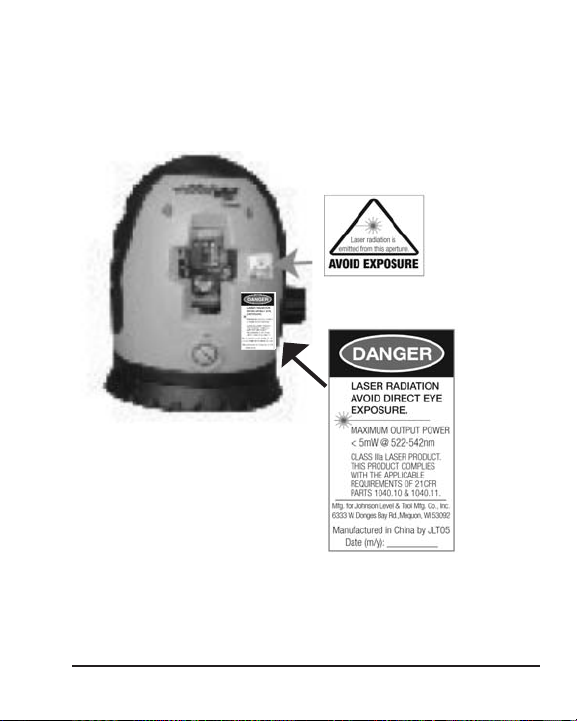
4. Location/Content of Warning Labels
Page 6
6
©2007 Johnson Level & Tool
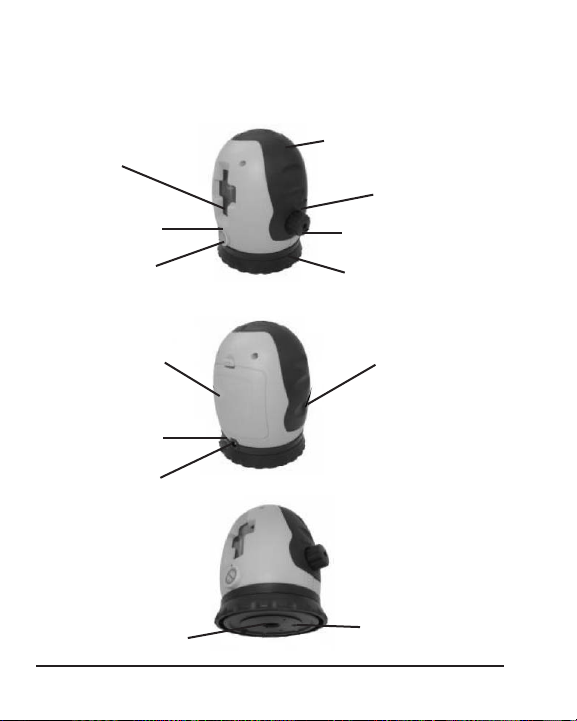
5. Location of Part/Components
Instrument
Laser Output
Window
Tilt “Manual Mode”
Rubber Cover
Tilt Manual Mode
Button
Power LED
On/Off Transportation
Lock Switch
360º Circle
Battery Case
Outlet LED
Outlet
Self-calibrating
Screw Portal
5/8” - 11 Screw
Thread
1/4” - 20 Screw
Thread
LED
Page 7

©2007 Johnson Level & Tool
7
Bracket Nomenclature
Connecting the Bracket to the Main-Body
1. Make the threaded holes mutually aligned. Align the 5/8” - 11
and 1/4” - 20 knob and hole.
2. Tighten instrument on the bracket by turning the handwheel
clockwise.
LED
Power LED Lighted LED means power-on
Extinguished LED means power-off
Flashing LED means weak battery
Main-body
Fixing Bolt
Magnet
Screw/Nail
Hanging
Hole
1/4" - 20
screw thread
Fixing
Strap Slot
Laser
Connecting
Knob
5/8" - 11
screw thread
Page 8

8
©2007 Johnson Level & Tool
Outlet LED Extinguished LED means no external power
Green LED means connected to external power or
battery is fully charged
Red LED means charging the battery
Tilt Manual Mode LED
Extinguished LED means the normal working state, and
the laser line will flash if out of the self-leveling range
Lighted LED means the laser is in the Tilt “Manual
Mode”. This turns off the out of level indicators
(sound and flash) and allows the operator to tilt the
unit for extreme slope
6. Operating Instructions
Battery Installation
Note: Always check to be sure that the on/off switch is in the off
position before removing and replacing batteries.
1. Open the battery-box cover and put in the battery pack into the
battery case according to polarity marked in the battery-box.
2. Snap the battery cover back on.
IMPORTANT: It is the responsibility of the user to verify the
calibration of the instrument before each use.
Page 9

©2007 Johnson Level & Tool
9
Power Adapter Usage
By connecting to the adapter, without the battery pack, the outlet LED
light will turn green and the instrument will be powered by the
adapter. If the rechargeable batteries are in the battery box, they
will be charged in this way and the
outlet LED light will be red in the
course of charging. When the LED
light turns green, the
batteries are fully charged.
Power on/off
With the rechargeable batteries or the adapter connected, turn the
on/off switch clockwise, the power LED will light and the instrument
will project a green laser cross beam (as shown below). By turning
the on/off switch counter-clockwise, the power LED will go out
and the instrument will be powered off and the compensator will be
locked in place.
Note:
• Pay attention to the polarity of the batteries.
• Do not charge alkaline batteries to avoid explosion.
• Used (discharged) batteries are hazardous waste and should be
disposed of properly.
Page 10

10
©2007 Johnson Level & Tool
7. Using the Product
The laser can turn around the center of the
scale 360 degrees.
The instrument can be placed on a
platform separately.
The instrument can be installed on
the bracket.
The instrument can be installed on a
tripod. (5/8” - 11 thread or 1/4” - 20
thread)
The instrument can be attached to a steel
plate while on its base.
The instrument can be fixed to a pipe
with the fixing strap while on its base.
Page 11

©2007 Johnson Level & Tool
11
8. Self-Check and Calibration
IMPORTANT: It is the responsibility of the user to verify the
calibration of the instrument before each use.
1. Set the instrument on a level flat head tripod centered between two walls
(marked 1 & 2) approximately 15 feet apart. (See fig. 1).
2. Point the instrument directly at wall 1. Turn the laser on and mark the
intersection of the beams as point A.
3. Turn the instrument 180 degrees so that the laser is pointed directly at wall
2. Turn the laser and mark the intersection of the beams as point B.
4. Move the instrument and the tripod so the laser is positioned approximately
2 feet away from wall 1 (see fig. 2). Level the tripod and position the
instrument on the tripod facing wall 1. Turn the laser on and mark the
intersection of the beams as point C.
5. Turn the laser off and rotate the laser
180 degrees so that it is
facing directly to wall 2.
6. Turn on the laser and mark the intersection of the beams as point D.
7. Measure the distance between
points A & C.
8. Measure the distance between
points B & D.
9. If the difference between points
A & C and points B & D are less
than 1/16”, your instrument is within
its tolerance.
Wall 1
Wall 2
Fig 1
Fig 2
Page 12

12
©2007 Johnson Level & Tool
Calibration
Re-calibration can be performed as described below.
1. Use a level to mark a horizontal reference line on the wall.
2. Power on the unit to compare the projected horizontal line with the
reference line.
3. If the projected laser line is tilted, power off the unit and lock the compensator. Screw off the calibration portal screw (figure 1) Use a 3mm hex head
wrench to calibrate the unit through its side calibration hole. Insert the hex
head wrench into the instrument and into the calibration screw. Turn the
3mm hex head wrench until the projected line is level. (figure 2) Turn the
hex head wrench clockwise if the line tilts to the right and counter-clockwise if the line tilts to the left.
4. If the horizontal line is too high or too low take off the rubber plugs behind
the rechargeable batteries (figure 3). Using a 3mm hex head wrench turn
the calibration screws, moving one screw at a time, clockwise to lower
the line and counter-clockwise to raise the line. Adjust the line to the correct height (figure 4).
Figure 1 Figure 2
Figure 3
Figure 4
Page 13

©2007 Johnson Level & Tool
13
9. Technical Specifications
Laser Wavelength 532nm±10
Laser Classification Class IIIa
Maximum Power Output ≤5mW
Accuracy ±1/8"/35 ft. (±3mm/10m)
Interior Range Up to 200 ft. (60m) depending upon light
conditions
Self-Leveling Range ± 5°
Power Supply Rechargeable battery pack or 6V adapter
(included)
Battery Life Approx. battery life 20 hours continuous use
Dimensions 3 7/8" x 4 1/4" x 5 1/8"
(98x110x130mm)
Weight 1.653 lbs. (0.75 Kg)
Working Temperature 32º to 104ºF (0º to 40ºC)
Center Screw Thread 5/8" – 11; 1/4" – 20
IP Protection Class 54
Page 14

14
©2007 Johnson Level & Tool
Installing partitions
Hanging pictures
Installing baseboards
Dormer installation
10. Application Demonstrations
Fixing doors and windows
Laying tile
Setting pipelines
Fixing cabinets
Page 15

©2007 Johnson Level & Tool 15
11. Care and Handling
• This laser unit is a precision tool that must be handled with care.
• Avoid exposing unit to shock vibrations and extreme temperatures.
• Before moving or transporting the unit, make sure that the unit
is turned off and is in the locked position. Failure to lock before
transport or storage may cause damage to the units inner
mechanisms and void warranty.
• Remove the batteries when storing the unit for an extended time
(more than three months) to avoid damage to the unit should
the batteries deteriorate.
• Always store the unit in its case when not in use.
• Avoid getting the unit wet.
• Keep the laser unit dry and clean, especially the laser output
window. Remove any moisture or dirt with a soft, dry cloth.
• Do not use harsh chemicals, strong detergents or cleaning solvents
to clean the laser unit.
Page 16

16 ©2007 Johnson Level & Tool
12. Product Warranty
Johnson Level & Tool offers a one year limited warranty on each its
products. You can obtain a copy of the limited warranty for a
Johnson Level & Tool product by contacting Johnson Level & Tool's
Customer Service Department as provided below or by visiting us
online at www.johnsonlevel.com. The limited warranty for each
product contains various limitations and exclusions.
Do not return this product to the store/retailer or place of purchase.
Required repair/calibration must be done by an authorized AccuLine
Pro™ service center or Johnson Level & Tool's limited warranty, if
applicable, will be void and there will be NO WARRANTY. Contact our
Customer Service Department to obtain a Return Material
Authorization (RMA) number for return to an authorized service center.
Proof of purchase is required.
NOTE: The user is responsible for the proper use and care of the
product.
It is the responsibility of the user to verify the calibration of the
instrument before each use.
For further assistance, or if you experience problems with this product
that are not addressed in this instruction manual, please contact our
Customer Service Department.
In the U.S., contact Johnson Level & Tool’s Customer Service
Department at 800-563-8553.
In Canada, contact Johnson Level & Tool’s Customer Service
Department at 800-346-6682.
Page 17

©2007 Johnson Level & Tool 17
13. Product Registration
Enclosed with this instruction manual you will find a warranty card to be
completed for product warranty registration. Product warranty registration
can also be completed online at our web site www.johnsonlevel.com.
You will need to locate the serial number for your product that is located
on the bottom of the unit. PLEASE NOTE THAT IN ADDITION TO ANY
OTHER LIMITATIONS OR CONDITIONS OF JOHNSON LEVEL &
TOOL'S LIMITED WARRANTY, JOHNSON LEVEL & TOOL MUST
HAVE RECEIVED YOUR PROPERLY COMPLETED WARRANTY CARD
WITHIN 30 DAYS OF YOUR PURCHASE OF THE PRODUCT OR ANY
LIMITED WARRANTY THAT MAY APPLY SHALL NOT APPLY AND
THERE SHALL BE NO WARRANTY.
Page 18

18 ©2007 Johnson Level & Tool
14. Accessories
AccuLine Pro™ accessories are available for purchase through
authorized AccuLine Pro dealers. Use of non-AccuLine Pro accessories
will void any applicable limited warranty and there will be NO WARRANTY.
If you need any assistance in locating any accessories, please contact
our Customer Service Department.
In the U.S., contact Johnson Level & Tool’s Customer Service
Department at 800-563-8553.
In Canada, contact Johnson Level & Tool’s Customer Service
Department at 800-346-6682.
Page 19

©2007 Johnson Level & Tool 19
Page 20

20 ©2007 Johnson Level & Tool
 Loading...