

Page 1
!
6249H_Manuals 10/18/12 2:48 PM Page 1
Model No. 40-6636 Self-Leveling
Model No. 40-6637 Self-Leveling
360º Line Laser w/4 Horizontal Dots
Model No. 40-6638 Self-Leveling
360º Line Laser with Detector
Model No. 40-6639 Self-Leveling 360º Line
Laser w/4 Horizontal Dots and Detector
Instruction Manual
Congratulations on your choice of this Self-Leveling 360º Line Laser. We suggest
you read this instruction manual thoroughly before using the instrument. Save this
instruction manual for future use.
These lasers emit one 360º horizontal laser beam or one 360º horizontal laser beam
with four dots that are 90º to each other. The laser features visual and audible out of
range indication and a pendulum-locking design. Beam visibility depends upon
lighting conditions in the work area.
This is a Class IIIa laser tool and
is manufactured to comply with
CFR 21, parts 1040.10 and
1040.11 as well as international
safety rule IEC 285.
360º Line Laser
©2012 Johnson Level & Tool 1
Page 2
6249H_Manuals 10/18/12 2:48 PM Page 2
Table of Contents
1. Kit Contents
2. Features and Functions
3. Safety Instructions
4. Location/Content
of Warning Labels
5. Location of Parts/Components
6. Operating Instructions
7. Using the Product
8. Self-Check & Fine Calibration
9. Technical Specifications
10. Application Demonstrations
11. Care and Handling
12. Product Warranty
13. Warranty Registration
14. Accessories
1. Kit Contents
Description Model No’s 40-6636 & 40-6637 Qty.
Self-Leveling 360º Line Laser 1
Wall Mount Bracket 1
“AA” Alkaline Batteries 4
Instruction Manual with Warranty Card 1
Soft-Sided Carrying Case 1
Description Model No’s 40-6638 & 40-6639 Qty.
Self-Leveling 360º Line Laser 1
Wall Mount Bracket 1
“AA” Alkaline Batteries 4
Detector with Bracket and 9V Battery 1
Instruction Manual with Warranty Card 1
Soft-Sided Carrying Case 1
2. Features and Functions
• Indoor and outdoor use (for outdoor use, must use 40-6780
detector included in 40-6638 and 40-6639).
• 40-6636 and 40-6638 emit a self-leveling 360º horizontal line
and the 40-6637 and 40-6639 emit a self-leveling 360º
horizontal line and 4 dots that are 90º to each other.
2 ©2012 Johnson Level & Tool
Page 3
6249H_Manuals 10/18/12 2:48 PM Page 3
3. Safety Instructions
Please read and understand all of the following instructions, prior
to using this tool. Failure to do so, may void the warranty.
DANGER!
Class IIIa Laser Product
Max. Power Output: ≤ 5mW
Wavelength: 625-645nm
THIS TOOL EMITS LASER RADIATION.
DO NOT STARE INTO BEAM.
AVOID DIRECT EYE EXPOSURE.
ATTENTION IMPORTANT
• Read all instructions prior to operating this laser tool. Do not remove any labels from tool.
• Do not stare directly at the laser beam.
• Do not project the laser beam directly into the eyes of others.
• Do not set up laser tool at eye level or operate the tool near a reflective surface as
the laser beam could be projected into your eyes or into the eyes of others.
• Do not place the laser tool in a manner that may cause someone to unintentionally
look into the laser beam. Serious eye injury may result.
• Do not operate the tool in explosive environments, i.e. in the presence of gases or
flammable liquids.
• Keep the laser tool out of the reach of children and other untrained persons.
• Do not attempt to view the laser beam through optical tools such as telescopes as
serious eye injury may result.
• Always turn the laser tool off when not in use or left unattended for a period of time.
• Remove the batteries when storing the tool for an extended time (more than 3 months)
to avoid damage to the tool should the batteries deteriorate.
• Do not attempt to repair or disassemble the laser tool. If unqualified persons attempt
to repair this tool, warranty will be void.
• Use only original Johnson
authorized dealer. Use of non-Johnson®parts and accessories will void warranty.
®
parts and accessories purchased from your Johnson
®
©2012 Johnson Level & Tool 3
Page 4
6249H_Manuals 10/18/12 2:49 PM Page 4
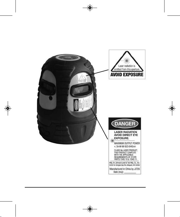
4. Location/Content of Warning Labels
4 ©2012 Johnson Level & Tool
Page 5
6249H_Manuals 10/18/12 2:49 PM Page 5
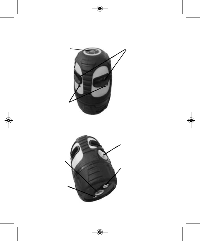
5. Location of Part/Components
Keypad
SelfCalibration
Aperture
5/8” Screw
Thread
1/4" Screw
Thread
©2012 Johnson Level & Tool 5
Laser Output Windows
Transportation Lock
ON/OFF
Battery Compartment
Screw
Page 6
6249H_Manuals 10/18/12 2:49 PM Page 6
6. Operating Instructions
IMPORTANT: It is the responsibility of the user to verify the
calibration of the instrument before each use.
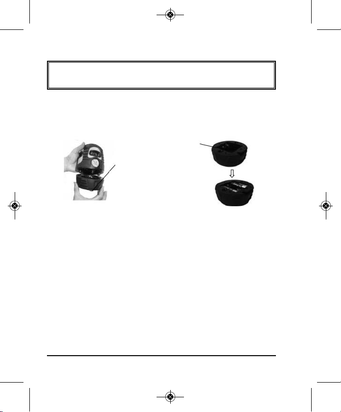
Battery Installation
Note: Always check to be sure that the on/off switch is in the off
position before removing and replacing batteries.
Polarity Indication of Battery
Battery
Compartment
Screws
Loosen the battery compartment screw, put 4 x AA alkaline batteries
into the battery compartment according to the polarity indication
shown in the battery compartment. Then put the battery
compartment back on and tighten the battery door screw.
Note:
• When power indication LED is flashing, alkaline batteries should
be replaced soon.
• Pay attention to the polarity of the batteries.
• Used (discharged) batteries are hazardous waste and should be
disposed of properly.
6 ©2012 Johnson Level & Tool
Page 7
6249H_Manuals 10/18/12 2:49 PM Page 7
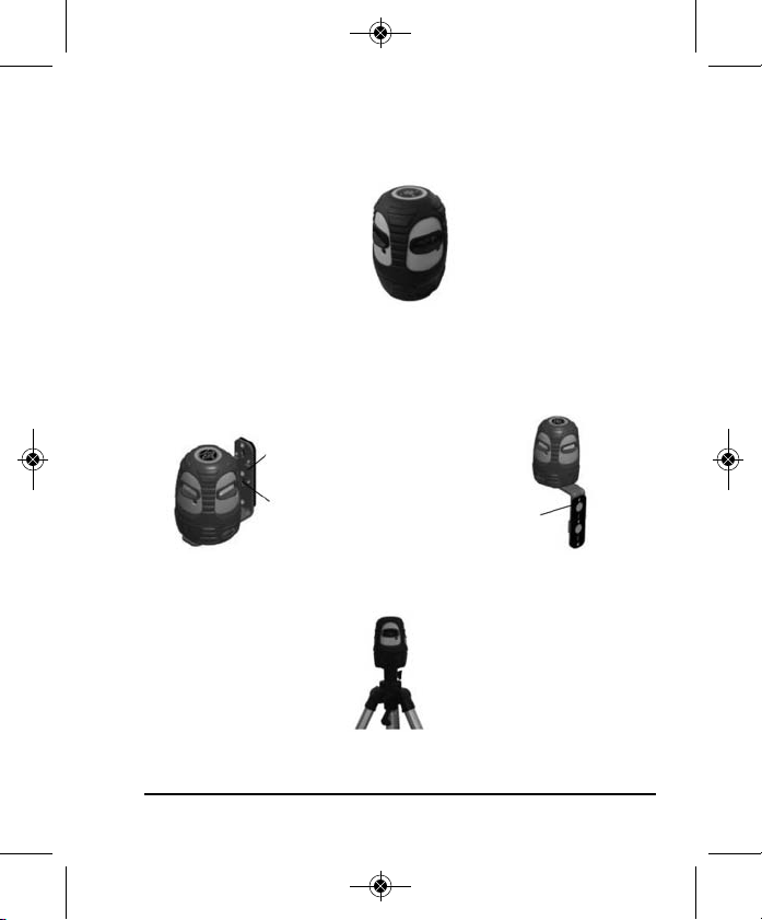
7. Using the Product
Place the laser onto any flat surface.
Connect the laser to the bracket with the 5/8” screw on the bottom of
the bracket, attach the bracket to any metal surface or strap it to a
column, or hang it on a wall.
Placement Strap
Screw holes
for hanging
on a wall
Magnet
The laser can also be placed on a 5/8” or 1/4” tripod.
©2012 Johnson Level & Tool 7
Page 8

6249H_Manuals 10/18/12 2:49 PM Page 8
Keypad Operations
Power LED
Manual Mode LED
Combination Button of Manual Mode and Pulse Mode
Pulse Mode LED
Power LED:
Light On: Power on
Light Off: Power off
Light Flashing: Low Battery
Manual Mode LED:
Light Flashing: Manual mode is on and laser is on with
compensator locked
Light Off: Manual mode is off
Pulse Mode LED:
Light On: Pulse mode is on and the laser can be used with the
40-6780 detector (included with 40-6638 & 40-6639)
Light Off: Pulse mode is off
Note: When manual mode is on, the laser does not self-level and
no out-of-level alarm is indicated.
8 ©2012 Johnson Level & Tool
Page 9

6249H_Manuals 10/18/12 2:49 PM Page 9
Output of the Laser:
Laser Line
Output of 40-6636 & 40-6638 Output of 40-6637 & 40-6639
Laser Dot
Laser Line
Combination Manual Mode Button/Pulse Mode Button:
When the laser is locked, press this button to enter into Manual
Mode, the Power LED is on, the Manual Mode LED flashes and the
laser line is on.
Press this button a second time, the Pulse Mode LED is on, the laser
line gets less bright and can be used with the detector.
Press this button a third time, Manual Mode LED, Power LED and
Pulse Mode LED are off.
When the laser is unlocked, the laser line will be on, press this button
to enter into Pulse Mode. The Pulse Mode LED is on and the laser
line will get less bright. Press this button again, and the laser will
exit the Pulse Mode and the Pulse Mode LED will turn off. When the
laser is locked, the laser line and LED will be off.
Notes:
1. The Manual Mode function is for out-of-level lines.
©2012 Johnson Level & Tool 9
Page 10

6249H_Manuals 10/18/12 2:49 PM Page 10
2. While the laser is in the unlocked position, the laser can not enter
into Manual Mode and will enter into self-leveling.
Power On/Off:
Turn the laser on by turning the compensator transportation lock dial
clockwise from the locked position to the unlocked position. The
power LED is on and the laser beam is on. To turn the laser off, turn
the compensator transportation lock dial counter-clockwise from the
unlocked position to the locked position. The power LED and laser
beam will turn off.
10 ©2012 Johnson Level & Tool
Page 11

6249H_Manuals 10/18/12 2:49 PM Page 11
Detector Usage (included in Model Nos. 40-6638 & 40-6639)
1. Technical Specifications
Detecting Accuracy: 0.019” ≤ 50 ft. (0.5mm ≤ 15m)
0.039” ≤ 100 ft. (1mm ≤ 35m)
0.059” ≥ 100 ft. (1.5mm ≥ 35m)
Automatic Shut-off: 6 minutes
Power Supply: 9V battery
Sound Indicator: fast tone, double tone and solid tone
LCD: Up arrow, Down arrow, Center sign
LED Indication: Up, Middle, Down
Dimensions: 5.905" x 2.992" x 1.142" (150 x 76 x 29mm)
Weight: 0.386 lb. (0.175kg)
Others: Rain and dust resistant
2. Components
With this laser detector, a line generated pulsed Johnson®laser can
be used both indoors with bright light and/or outdoors in the
sunlight where the beams are not visible.
©2012 Johnson Level & Tool 11
Page 12

6249H_Manuals 10/18/12 2:49 PM Page 12
1. Horizontal Vial
2. Reception Window
3. Sound On/Off Key
4. Power On/Off Key
5. Vertical Vial
6. Display Window
7. Front On Grade Mark
8. Beeper
9. Top Indicator Light
10. Middle Indicator Light
11. Bottom Indicator Light
12. Rear On Grade Mark
13. Rod Bracket Thread
14. Battery Door
Display Window Symbols
1. Power On
2. Low Voltage
3. Coarse/Fine
4. Sound On
5. Position Indication Arrows
12 ©2012 Johnson Level & Tool
Page 13

6249H_Manuals 10/18/12 2:49 PM Page 13
3. Operation Instructions
1. Battery Installation
Open the battery door, and put in one 9V battery according to the
polarity shown inside. Then snap the battery door
back.
Note:
• Remove the battery when the unit is being
stored for a long time.
• Replace the battery when the low voltage
indicator shows a low battery.
2. Operating Instructions
IMPORTANT: This detector will only work when the laser is in
the pulse mode.
A. Press the Power on/off key: The detector
will beep twice and all the symbols will be
displayed on the display window. After
0.5 seconds the detector will enter its
detecting mode.
B. Detecting the horizontal laser signal: Put
the detector in a vertical position and center
the bubble in the horizontal vial with the
reception window facing the laser. A down
arrow shown on the display window and a lit
red light indicates the laser signal is below the detectors on grade
©2012 Johnson Level & Tool 13
Page 14

6249H_Manuals 10/18/12 2:49 PM Page 14
mark. An up arrow plus a yellow lit light indicates the laser signal is
above the detectors on grade mark. A middle sign plus a lit green light
indicates the laser signal is on grade.
Note: When the laser signal moves towards the
center position, the displayed up or down
arrows will decrease in size, until the center
single line appears.
C. Detecting the vertical laser signal: Put the
detector in a horizontal position (center the bubble
in the horizontal vial) with the reception window
and indicator lights facing up. Have the reception
window face the unit to receive the vertical laser
signal. Left arrow shown on LCD plus a lit red light
indicates the laser signal is on the left side of center.
A middle sign with a lit green light indicates the
laser signal is on the middle position. A right arrow plus a lit
yellow light indicates the laser signal is on the right side of center.
D. Press the Power on/off key to power off the detector. The
detector will beep twice for off.
3. Sound Function
Pressing the sound key when the unit
is powered-on. This will switch the
unit between sound on and sound off,
Sound
On
Sound
Off
note the sound sign indication on LCD.
14 ©2012 Johnson Level & Tool
Page 15

6249H_Manuals 10/18/12 2:49 PM Page 15
Sound function on:
• If the laser signal is on the top (left) side, then the detector will
give a fast tone.
• If the laser signal is on the bottom (right) side, then the detector
will give a double tone.
• If the laser signal is on the middle, then the detector will have a
solid tone.
4. Automatic Shut-Off Function
When not receiving a laser signal and with no operation of the keys
for six continuous minutes, the unit will power off automatically to
preserve battery life.
5. Low Battery Indicator Function
• When the power indicator sign is blinking, it
indicates that the battery is low and should
be replaced.
• A very low battery will result in an automatic
power-off, which requires the user to
replace before continued operation.
Blink
©2012 Johnson Level & Tool 15
Page 16

6249H_Manuals 10/18/12 2:49 PM Page 16
8. Self-Check & Fine Calibration
IMPORTANT: It is the responsibility of the user to verify the
calibration of the instrument before each use.
Accuracy Check
1. Set the device on a platform, a minimum of 5 meters away from
an indoor wall, with laser squarely facing wall.
2. Turn the device on, and after it self-levels, make a mark on the
wall (Label this mark ‘A’), then draw a vertical line through ‘A’.
3. Turn the device 90°, and after it self-levels, make a mark at the
intersection of the laser line/vertical line. (Label this mark as ‘B’).
Do the same two more times, labeling the marks as ‘C’ and ‘D’.
4. Measure the distance between the two points with the greatest
distance among A, B, C, D. This will be measurement ‘h’. If
‘h’=2mm, the accuracy of the instrument is within spec.
If ‘h’> 2mm, the accuracy of the instrument is out of tolerance,
and adjustment is necessary.
Adjustment of Self-Calibration
According to the results of #4 above, mark ‘O’ at ‘h’/2. ‘h’/2 is the
center of the highest and lowest points among A, B, C, D.
1. Aim the self-calibration aperture 1 of instrument to the
wall, and adjust to make the laser line meet ‘O’.
2. Aim the self-calibration aperture 2 of instrument to the
wall, and adjust to make the laser line meet ‘O’.
16 ©2012 Johnson Level & Tool
Page 17

6249H_Manuals 10/18/12 2:49 PM Page 17
When adjusting, note:
a. Use a 2.5mm hex-head tool (allen wrench).
b. The adjustment of each aperture may influence each other.
This means that adjusting Aperture 1 may cause
Aperture 2 to change, so a re-check of the previous
Aperture adjustment may be required.
c. The adjustment of the self-calibration screw should not
exceed 4 complete rotations (clockwise or counterclockwise direction).
d. If the instrument cannot be calibrated via the Apertures
(device is too far out of spec), then please contact a
distributor, repair facility, or Johnson Level & Tool
Customer Service.
©2012 Johnson Level & Tool 17
Page 18

6249H_Manuals 10/18/12 2:49 PM Page 18
9. Technical Specifications
Laser Wavelength 635nm±10nm
Laser Classification Class IIIa
Maximum Power Output ≤5mW
Accuracy ±1/8"/50 ft. (±1mm/10m)
Interior Range Up to 200 ft. (60m) depending upon light
conditions
Exterior Range Up to 300 ft. (90m) with detector
(included in 40-6638 & 40-6639)
Self-leveling Range ±5°
Power Supply 4 “AA” alkaline batteries
Battery Life Approx. battery life 10 hours continuous use
Dimensions 3.74" x 5.11" (95 x 130mm)
Weight 1.869 lbs (0.7 Kg)
Working Temperature 14°F to 113°F (-10°C to +45°C)
Center Screw Thread 5/8" – 11
IP Protection 54
18 ©2012 Johnson Level & Tool
Page 19

6249H_Manuals 10/18/12 2:49 PM Page 19
10. Application Demonstrations
Installing baseboards
Installing tile Aligning doors and windows
©2012 Johnson Level & Tool 19
Installing partitions
Page 20

6249H_Manuals 10/18/12 2:49 PM Page 20
11. Care and Handling
• This laser unit is a precision tool that must be handled with care.
• Avoid exposing unit to shock vibrations and extreme temperatures.
• Before moving or transporting the unit, make sure that the unit is turned off.
• Remove the batteries when storing the unit for an extended time (more than
three months) to avoid damage to the unit should the batteries deteriorate.
• Always store the unit in its case when not in use.
• Avoid getting the unit wet.
• Keep the laser unit dry and clean, especially the laser output window.
Remove any moisture or dirt with a soft, dry cloth.
• Do not use harsh chemicals, strong detergents or cleaning solvents to clean
the laser unit.
12. Product Warranty
Johnson Level & Tool offers a three year limited warranty on each of its products.
You can obtain a copy of the limited warranty for a Johnson Level & Tool
product by contacting Johnson Level & Tool's Customer Service Department,
as provided below, or by visiting our web site at www.johnsonlevel.com. The
limited warranty for each product contains various limitations and exclusions.
Do not return this product to the store/retailer or place of purchase.
Non-warranty repairs and course calibration must be done by an authorized
Johnson®service center or Johnson Level & Tool's limited warranty, if
applicable, will be void and there will be NO WARRANTY. Contact one of our
service centers for all non-warranty repairs. A list of service centers can be
found on our web site at www.johnsonlevel.com or by calling our Customer
Service Department. Contact our Customer Service Department for Return
Material Authorization (RMA) for warranty repairs (manufacturing defects
only). Proof of purchase is required.
20 ©2012 Johnson Level & Tool
Page 21

6249H_Manuals 10/18/12 2:49 PM Page 21
NOTE: The user is responsible for the proper use and care of the product. It is the
responsibility of the user to verify the calibration of the instrument before each use.
For further assistance, or if you experience problems with this product that are not
addressed in this instruction manual, please contact our Customer Service Dept.
In the U.S., contact Johnson Level & Tool’s Customer Service Department at
888-9-LEVELS.
In Canada, contact Johnson Level & Tool’s Customer Service Department at
800-346-6682.
13. Warranty Registration
Enclosed with this instruction manual you will find a warranty
registration card to be completed for your product. You will need to
locate the serial number for your product that is located on the bottom
of the unit. PLEASE NOTE THAT IN ADDITION TO ANY OTHER
LIMITATIONS OR CONDITIONS OF JOHNSON LEVEL & TOOL'S
LIMITED WARRANTY, JOHNSON LEVEL & TOOL MUST HAVE
RECEIVED YOUR PROPERLY COMPLETED WARRANTY CARD AND
PROOF OF PURCHASE WITHIN 30 DAYS OF YOUR PURCHASE OF
THE PRODUCT OR ANY LIMITED WARRANTY THAT MAY APPLY
SHALL NOT APPLY AND THERE SHALL BE NO WARRANTY.
©2012 Johnson Level & Tool 21
Page 22

6249H_Manuals 10/18/12 2:49 PM Page 22
14. Accessories
Johnson®accessories are available for purchase through authorized
®
Johnson
applicable limited warranty and there will be NO WARRANTY. If you need
any assistance in locating any accessories, please contact our
Customer Service Department.
In the U.S., contact Johnson Level & Tool’s Customer Service
Department at 888-9-LEVELS.
In Canada, contact Johnson Level & Tool’s Customer Service
Department at 800-346-6682.
dealers. Use of non-Johnson®accessories will void any
22 ©2012 Johnson Level & Tool
 Loading...