

Page 1
6274H-1_Manuals 9/26/12 10:44 AM Page 1
Electronic Self-Leveling Dual Grade
Horizontal / Vertical Rotary Laser
Model No. 40-6582
Instruction Manual
Congratulations on your choice of this Electronic Self-Leveling Dual Grade
Horizontal / Vertical Rotary Laser. We suggest you read this instruction
manual thoroughly before using the instrument. Save this instruction manual
for future use.
This tool emits one rotating laser beam plus one plumb beam and is ideal for
laying out indoor or outdoor construction projects.
This is a Class IIIa laser tool and is manufactured to comply with CFR 21, parts
1040.10 and 1040.11 as well as international safety rule IEC 285.
©2012 Johnson Level & Tool 1
Page 2
6274H-1_Manuals 9/26/12 10:44 AM Page 2
Table of Contents
1. Kit Contents
2. Features and Functions
3. Safety Instructions
4. Location/Content
of Warning Labels
5. Location of Parts/Components
6. Operating Instructions
7. Using the Product
8. Self-Check & Fine Calibration
9. Technical Specifications
10. Application Demonstrations
11. Care and Handling
12. Product Warranty
13. Warranty Registration
14. Accessories
1. Kit Contents
Description Model No. 40-6582 Qty.
Electronic Self-Leveling Dual Grade Horizontal/Vertical Rotary Laser 1
Li-ion Rechargeable Battery Pack 1
Battery Adapter 1
Detector with 9V Battery and Clamp 1
Remote with 2 AA Batteries 1
Alkaline Battery Compartment (batteries not included) 1
Vertical Bracket 1
Fine Adjusting Plate 1
Sighting Scope 1
Instruction Manual with Warranty Card 1
Hard-Shell Carrying Case 1
2 ©2012 Johnson Level & Tool
Page 3
6274H-1_Manuals 9/26/12 10:44 AM Page 3
2. Features and Functions
• Large electronic self-level range: When beyond the ±8°
leveling range, the laser beam will flash, laser stops rotating
and an audible alarm activates.
• Vertical and horizontal working modes: Electronic self-leveling
in both horizontal and vertical mode with one rotating laser
beam and one 90° split beam.
• Three rotational speeds: 300, 600 and 1100 RPM
• Scan function adjusts the scan line size and scan direction.
• Out-of-level alarm ensures the working accuracy.
• Fine self-calibration function.
• In “Tilt Mode” the laser will stop rotating and flash when
bumped to ensure work accuracy.
• Programmable dual slope function allows the user to perform
slope in both X & Y axis.
• Dust and rain resistant.
©2012 Johnson Level & Tool 3
Page 4
6274H-1_Manuals 9/26/12 10:44 AM Page 4
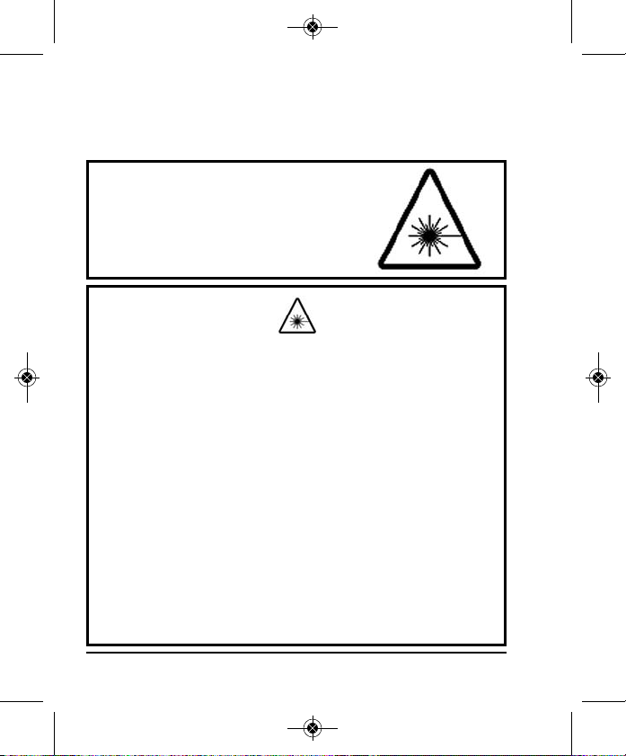
3. Safety Instructions
Please read and understand all of the following instructions, prior
to using this tool. Failure to do so, may void the warranty.
DANGER!
Class IIIa Laser Product
Max. Power Output: ≤ 5mW
Wavelength: 625-645nm
THIS TOOL EMITS LASER RADIATION.
DO NOT STARE INTO BEAM.
AVOID DIRECT EYE EXPOSURE.
ATTENTION IMPORTANT
• Read all instructions prior to operating this laser tool. Do not remove any labels from tool.
• Do not stare directly at the laser beam.
• Do not project the laser beam directly into the eyes of others.
• Do not set up laser tool at eye level or operate the tool near a reflective surface as
the laser beam could be projected into your eyes or into the eyes of others.
• Do not place the laser tool in a manner that may cause someone to unintentionally
look into the laser beam. Serious eye injury may result.
• Do not operate the tool in explosive environments, i.e. in the presence of gases or
flammable liquids.
• Keep the laser tool out of the reach of children and other untrained persons.
• Do not attempt to view the laser beam through optical tools such as telescopes as
serious eye injury may result.
• Always turn the laser tool off when not in use or left unattended for a period of time.
• Remove the batteries when storing the tool for an extended time (more than 3 months)
to avoid damage to the tool should the batteries deteriorate.
• Do not attempt to repair or disassemble the laser tool. If unqualified persons attempt
to repair this tool, warranty will be void.
• Use only original Johnson
authorized dealer. Use of non-Johnson®parts and accessories will void warranty.
®
parts and accessories purchased from your Johnson
®
4 ©2012 Johnson Level & Tool
Page 5
6274H-1_Manuals 9/26/12 10:44 AM Page 5
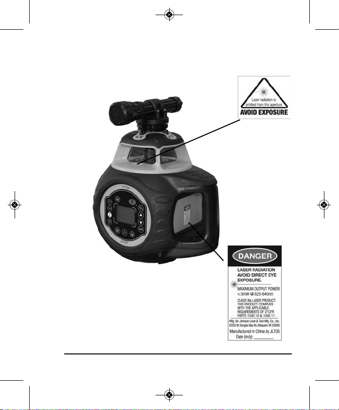
4. Location/Content of Warning Labels
©2012 Johnson Level & Tool 5
Page 6
6274H-1_Manuals 9/26/12 10:44 AM Page 6
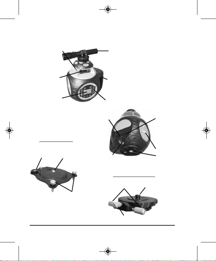
5. Location of Part/Components
Laser Output Window
Rotating Head
LCD Display
Vertical Bracket
Circular Vial
5/8” x 11 Screw
Thread
Leveling Knobs
Charging Port
Battery Cover Screw
Sighting Scope
Handle
Keypad
Fine Adjusting Plate
Fine Adjustment
Knobs
Lock Knob
Battery
Cover
5/8” x 11
Screw
Thread
5/8” x 11 Screw
Thread
6 ©2012 Johnson Level & Tool
Page 7
6274H-1_Manuals 9/26/12 10:44 AM Page 7
6. Operating Instructions
IMPORTANT: It is the responsibility of the user to verify the
calibration of the instrument before each use.
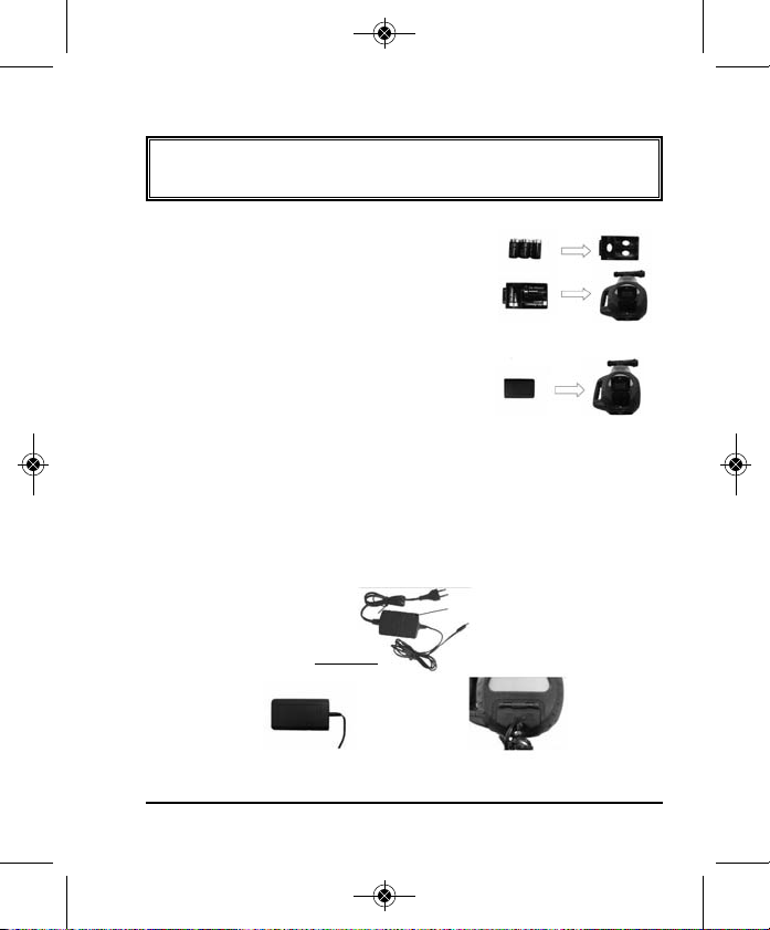
Alkaline Battery Installation:
Put 3 “D” alkaline batteries (not included)
into the battery pack according to the polarity
direction, then insert the battery pack into the
laser. (Note: Batteries facing up.)
Rechargeable Battery Pack Installation:
Install the rechargeable battery pack into
the laser.
Charging the Rechargeable Battery Pack:
Charge the rechargeable battery pack by inserting the charger into
the charging port. The LED on the charger is red during the charging
process; the LED on the charger will turn green when the battery is
fully charged.
Charging LED
Charger
Charge the rechargeable battery pack
outside the laser
©2012 Johnson Level & Tool 7
Charge the rechargeable battery pack with
battery pack inside the laser
Page 8
6274H-1_Manuals 9/26/12 10:44 AM Page 8
Note:
(1) Charge the rechargeable battery when the battery power is
low (battery symbol on the LCD is flashing). This will extend
the battery life.
(2) If the laser is not going to be used for a long period of time,
charge the rechargeable battery every 2-3 months.
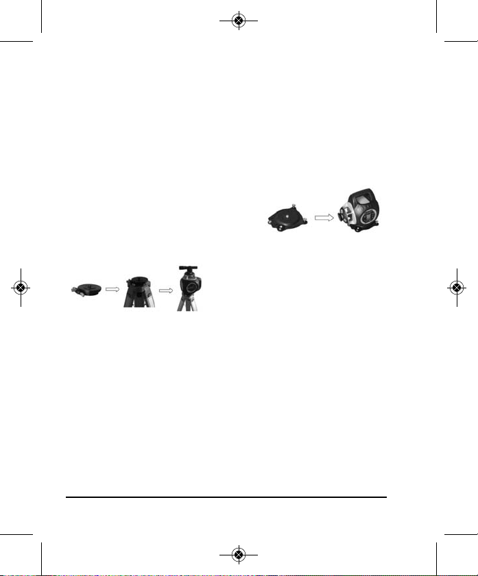
Use of the Vertical Bracket and Fine Adjusting Plate:
Screw the vertical bracket onto the side of
the laser with the vertical bracket leveling
knobs at the bottom of the laser and the
circular vial at the top of the laser.
Vertical Bracket
For exact positioning of the X or
Y-axis, screw the Fine Adjusting
Plate on the tripod and then screw
Fine Adjusting Plate
the laser to the Fine Adjusting Plate.
Using the Sighting Scope, rotate
the laser to the exact position required. Use the Fine Adjusting
Knobs for fine movement. Use the Lock Knob when positioned in
the correct position.
8 ©2012 Johnson Level & Tool
Page 9
6274H-1_Manuals 9/26/12 10:44 AM Page 9
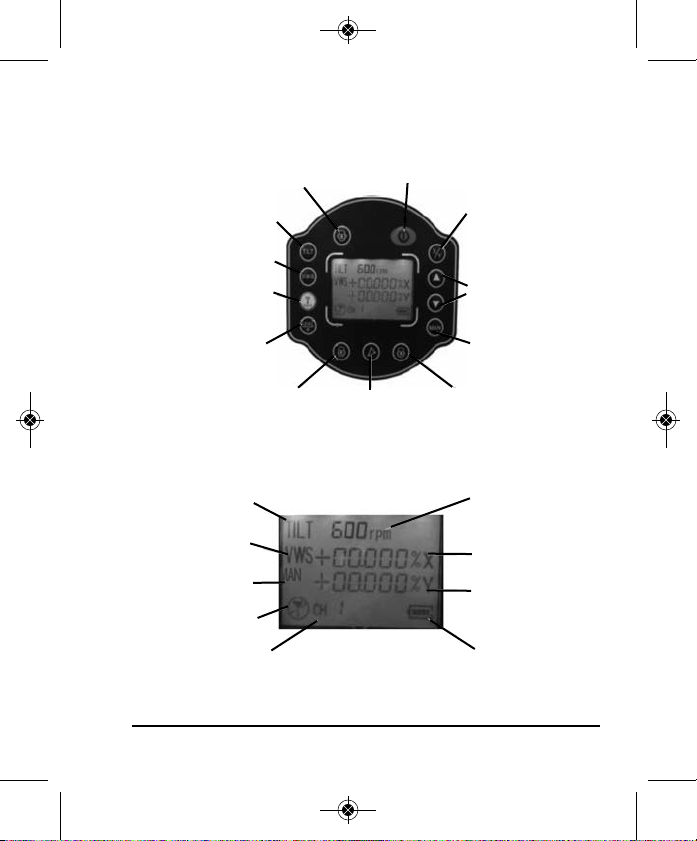
7. Using the Product
Keypad Controls
Rotating Speed Button On/Off Button
Tilt Button
Vibrate/VWS Button
Remote Channel Button
Level Button /
LCD Backlight Button
Scan / Dot Clockwise
Button
Scan / Dot Button
Grade Axis and
Position Button
Grade Value Buttons
Manual Mode Button
Scan / Dot
Counterclockwise Button
LCD Display
Tilt Mode
Vibrate VWS Mode
Manual Mode
Remote On/Off
Remote Channel
©2012 Johnson Level & Tool 9
Rotating Speed
X-Axis Grade Value
Y-Axis Grade Value
Battery Capacity
Page 10

6274H-1_Manuals 9/26/12 10:44 AM Page 10
Power On/Off Button:
Press this button to power on/off the laser.
The laser is in self-leveling status when powered on.
Default rotate speed is 600 RPM
Default grade for X-axis and Y-axis is 0.
The remote channel will display CH1.
If there is a matched remote control which is on, the remote
status will display . If there is not a matched remote, it will
display .
When powered on, the laser will automatically check the battery
capacity.
When powering on the laser it will enter into the self-leveling mode.
The TILT display will blink for thirty seconds after the laser starts
to rotate. During these thirty seconds, if the laser is moved, it will
stop rotating and re-level itself. After thirty seconds, the laser
will enter into the TILT mode and the LCD will show a solid
TILT display. (See TILT button)
Grade axis and Grade Value Button:
With the laser on, press the Grade Axis and Position button and hold
for two seconds. The laser will beep once and the laser will enter the
X-axis grade setting mode. The X-axis symbol “X” and axis direction
symbol (+) will flash. A short press of the button will move the
position to the next symbol. Pressing the Grade Value Buttons
will change the values. When the X-axis setting is completed, press
the grade axis button for two seconds to enter the Y-axis grade
10 ©2012 Johnson Level & Tool
Page 11

6274H-1_Manuals 9/26/12 10:44 AM Page 11
setting mode, the Y-axis symbol “Y” and axis direction symbol (+) will
flash. The setting method is the same as the X-axis.
After the Y-axis grade setting is completed, press the key for two
seconds to confirm the grade setting. The laser will beep once
and will quit the grade setting mode and start to work under the
confirmed grade.
Note: If there is no buttons pressed for eight seconds in the
grade setting mode, the laser will confirm the current grade
setting data automatically. The laser will beep once and leave
the grade setting mode.
Rotating Speed Button:
Press this button to select the rotating speed from 300 RPM, 600
RPM or 1100 RPM.
Scan / Dot Button:
Press this button to activate the scan mode. Press this button again
to change the scan angle as follows:
Rotating the Scan Line
1. Press the clockwise button on either the laser keypad or remote
and the scan line moves to the right.
2. Press the counter-clockwise button and the scan line moves to
the left.
©2012 Johnson Level & Tool 11
Page 12

6274H-1_Manuals 9/26/12 10:44 AM Page 12
TILT Button:
When turning on the laser, the laser will self-level and begin to rotate.
The TILT symbol on the LCD will blink for thirty seconds after the laser
begins to rotate. During these thirty seconds if the laser is moved the
laser will stop rotating , re-level and begin to rotate again. After thirty
seconds the TILT symbol will stop blinking and will become solid. If the
laser is moved when the TILT symbol is solid, the laser will stop rotating.
The laser beam will blink on and off and the TILT symbol will blink
quickly alerting the user that the height of instrument may have been
changed. Pressing the level button will allow the laser to re-level and
start rotating again and the TILT mode will repeat.
Vibrate VWS Button:
When pushing this button once the VWS symbol will be displayed on
the LCD. Note: if the TILT mode display is turned off, pushing the
VWS button will turn the TILT mode display on. In this mode, the
laser will not react to slight vibration near the laser. To turn the VWS
mode display off, push the button one more time.
MAN Button:
When holding this button in for three seconds, the laser will enter into
manual mode. The self-leveling motors are turned off and the laser
will rotate in any position. Note: Grade value cannot be entered in
manual mode. To exit manual mode, hold the button in again for
three seconds or push the TILT button to enter TILT mode.
12 ©2012 Johnson Level & Tool
Page 13

6274H-1_Manuals 9/26/12 10:44 AM Page 13
Level Button/LCD Backlight Button:
Push this button once to start self-leveling after the laser has been
moved in TILT mode. Hold this button in for three seconds to turn on
the LCD backlight.
Remote Channel Button:
Push this button to switch the remote channel from CH1 to CHF.
Vertical Applications:
Place the laser on its side using the vertical bracket. Center the
circular bubble vial with the use of the leveling knobs. All functions
work except the grade setting function. When the laser is in the selfleveling mode, the Z-axis is self-leveling. Press the buttons
to make the laser line move left or right. In Manual mode, the Z-axis
is not self-leveling, press the button for two seconds to enter into
the X-axis manual adjusting mode. Press the buttons to
make the laser line move left and right. Press the button again
to enter the Y-axis manual adjusting mode. Press to make
the laser split beam/dot move up or down.
Note: A short press of the buttons will adjust the line slowly.
Holding down the buttons will move the line quickly.
©2012 Johnson Level & Tool 13
Page 14

6274H-1_Manuals 9/26/12 10:44 AM Page 14
Battery Status Indicator:
When powered on, the laser will automatically check the battery
capacity and show the following status:
Full battery
Half battery
Low battery
Very low battery and laser should be charged
Empty battery and laser needs to be charged
Using the Remote Control:
1. Install two “AA” batteries in the battery compartment following the
diagram inside the compartment.
2. With the laser turned on, turn on the remote by pressing the
power button.
3. The LCD on the remote will display the following:
14 ©2012 Johnson Level & Tool
Page 15

6274H-1_Manuals 9/26/12 10:44 AM Page 15
4. The laser and remote default into channel (CH1) 1. The remote
control will only work when the laser and remote are on the same
channel. If other lasers are in the area, the remote and laser can
be changed from CH1 to CH9 and CHA to CHF making it so the
remote will only work for a specific laser. To change the remote
channel, press the remote button.
5. If the LCD on the laser displays the remote is not turned on, is
too far away from the laser or is on a different channel.
6. If the LCD displays on the laser and remote, the remote and
laser are on the same channel.
Note: The battery symbol display on the remote shows the battery
strength of the remote batteries and not the laser battery strength.
The differences between the remote button and laser buttons are
as follows:
1. Holding the Level/Backlight button on the remote for three
seconds will turn on the remote backlight. To turn off the backlight, hold the same button in again for another three seconds.
2. One press of the manual button will put the laser in “sleep”
mode. All the laser settings will be saved on the laser. The only
button that will work on the laser is the power button. The
only buttons that will work on the remote is the manual
button and power button. Another press of the manual
button will turn the laser back on to its original setting. This
“sleep” mode can be used to save on the battery life if the laser is
not going to be used for a period of time.
If the laser is not used after sixty minutes in “sleep” mode, the laser
will power off automatically and all stored information will be lost.
©2012 Johnson Level & Tool 15
Page 16

6274H-1_Manuals 9/26/12 10:44 AM Page 16
Detector Usage
Two-Sided Laser Detector with Clamp
Model No. 40-6715
The 40-6715 laser detector is an indispensable accessory when
using rotary laser levels. The main function of the detector is to
detect the position of the laser signals that are transmitted by rotary
lasers. This detection quickly and precisely provides the user with the
horizontal reference.
This product features high sensitivity, a double-faced display, low
power consumption, good reliability and easy manipulation. It can be
used with most types of rotating laser levels.
1. Technical Specifications
Detecting accuracy: Fine: ±0.039" (±1mm)
Automatic Shut-off: 6 minutes ±1 minute
Power Supply: 9V battery, 30 hrs continuous use
Sound indicator: slow short beep, rapid short beep and
LED display: down arrow, up arrow, horizontal on
Dimensions: 6.30" x 3.35" x 1.10" (160 x 85 x 28mm)
Weight: 1 lb. (0.45kg)
Others: Rain and dust resistant
16 ©2012 Johnson Level & Tool
Coarse 1: ±0.098" (±2.5mm)
when range ≥ 492 ft. (150m)
Coarse 2: ±0.394" (±10mm)
when range ≥ 492 ft. (150m)
(with LCD illumination off)
continuous sound
grade bar
Page 17

6274H-1_Manuals 9/26/12 10:44 AM Page 17
2. Components
(a) Exterior Instruction
(b) Display
1. Power on symbol
2. Low battery indicator
3. Fine/Coarse symbol
4. Beeper symbol
5. Position indication arrows
Power Key: Turn on/off the power
1) Horizontal vial
2) Front display window
3) Front on grade mark
4) Vertical vial
5) LED key
6) Power key
7) Beeper
8) Reception window
9) Fine/Coarse accuracy key
10) Beeper key
11) Back display window
12) Back on grade mark
13) Bracket screw thread
14) Battery cover screw
15) Battery cover
Fine/Coarse Accuracy Key: Switch detecting accuracy
LED Key: Turn on/off the LCD’s light
Volume Key: Cycles between high, low and off
©2012 Johnson Level & Tool 17
Page 18

6274H-1_Manuals 9/26/12 10:44 AM Page 18
3. Operation Guide
(a) Battery Installation
• Open the battery cover door by turning the battery cover screw
counter-clockwise. Put the battery into the
battery case noting the polarity shown in
the battery compartment.
• Put the battery cover door back, and tighten
the screw.
Note: 1) Remove the battery when the unit is being stored for a
long time.
2) When the low battery indicator is displayed, change the
battery soon.
4. Operating Instructions
Power On
Press the power key to turn the unit on. The
LCD display will illuminate all the indicator
segments for 0.5 second (Fig.2). When the
indicator segments are no longer
illuminated, the detector is ready for use.
Note: The LCD display will still have the
Figure 2
power, detection and sound indicators illuminated (Fig. 3).
Figure 3
18 ©2012 Johnson Level & Tool
Page 19

6274H-1_Manuals 9/26/12 10:44 AM Page 19
Fine/Coarse accuracy key
Power on and press the
fine/coarse accuracy key, the
unit will cycle between three
accuracy options: fine, coarse
1, coarse 2. The accuracy
symbol displayed on the LCD will change.
Volume Key
Power on and press the volume
key, the unit will cycle between a
high sound, low sound and mute.
The sound symbol displayed on the LCD will change accordingly.
Note: There will be two beeps when turning the unit on and off.
There will be one beep when changing functions.
Detecting Laser Level Signals
While detecting laser signals, the LCD will display as follows: (take
the set-up state of high sound and fine detection as an example)
Laser signal
Laser signal
Laser signal
The laser signal is down
Sound: rapid short beeps
©2012 Johnson Level & Tool 19
The laser signal is up
Sound: slow short beeps
Horizontal bar indicated on-grade
Sound: continuous sound
No laser signal is detected
Sound: no sound
Page 20

6274H-1_Manuals 9/26/12 10:44 AM Page 20
When the laser signal is near the on-grade mark, the displayed up
and down arrows will decrease as the distance to the on-grade mark
decreases.
Laser signal Laser signal Laser signal Laser signal
1. When detecting a horizontal laser signal, it is
important to have the bubble vial centered, as the
deflection of the receiver will influence its receiving
accuracy.
2. When detecting a vertical laser signal, it is important
to have the bubble vial centered, as the deflection of
the receiver will influence its receiving accuracy.
3. Keep the reception window facing the laser while detecting.
4. Hold the unit stable while detecting.
LED Function
Power on and press the LED key, the LCD will now be backlit.
Automatic Shut-off Function
When the unit does not receive a laser signal for 6 minutes, the
unit will power off automatically.
Low Battery Display Function
When the battery sign blinks on the LCD, the battery is
low and needs to be replaced. If the battery is very low,
the unit will power off automatically. Replace the battery.
20 ©2012 Johnson Level & Tool
Page 21

6274H-1_Manuals 9/26/12 10:44 AM Page 21
Rod Clamp
Connecting to the rod clamp.
Connecting to the grade rod.
5. Detector Maintenance
• Keep the unit, particularly the reception window, clean. If it does get dirty,
use a cloth to wipe it clean.
©2012 Johnson Level & Tool 21
Page 22

6274H-1_Manuals 9/26/12 10:44 AM Page 22
8. Self-Check & Fine Calibration
IMPORTANT: It is the responsibility of the user to verify the
calibration of the instrument before each use.
The instrument must
be self-checked for
accuracy periodically,
specifically before a
large project, where
accuracy is critical.
If the accuracy is found to be beyond tolerance, some adjustment
may be made as follows.
X-Axis and Y-Axis Accuracy Check:
1. Place a table indoors, approximately 20m from a wall. Place the
instrument on the table with the X-axis facing the wall.
2. Power the instrument on and allow it to self-level. Adjust the
rotating speed to make the output laser line clear and visible.
Mark a vertical line on the wall that intersects the laser line from
the instrument. Mark a line where the laser line hits the vertical
line, and label as ‘A’.
(Turning in a clockwise direction):
A = X+
B = Y+
C = XD = Y-
h
22 ©2012 Johnson Level & Tool
Page 23

6274H-1_Manuals 9/26/12 10:44 AM Page 23
3. Rotate the instrument 90°, and after self-level completes, mark a
line and label as ‘B’. Repeat two more times, labeling lines as ‘C’,
and ‘D’.
4. Measure the vertical distance ‘h’ between the highest and the
lowest points among A, B, C, and D.
5. If h=2mm or less, accuracy is qualified. If h>2mm but <10mm,
adjust the calibration. If h>10mm, please contact an authorized
service center or dealer for repair.
Z-Axis Accuracy Check:
1. Place the instrument
into the vertical
position, using
vertical mount
bracket included.
Power on the unit
and allow to auto level. Measure the height of H2 between the
horizontal laser line and the platform.
2. Mark a point ‘0’ under point 0, which is (H1-H2). Point ‘0’ is a
reference point for the Z-axis.
3. Project the laser to the vertical line on the wall and measure the
distance “h” between the projected point and the point ‘0’.
4. If h< 2mm, the accuracy is qualified. If h> 2mm but < 10mm, the
accuracy is beyond tolerance and calibration is required.
If h > 10mm, please contact an authorized service center or
dealer for repair.
h’
Projected
Point
©2012 Johnson Level & Tool 23
Page 24

6274H-1_Manuals 9/26/12 10:44 AM Page 24
Accuracy Calibration of the X and Y-Axis:
1. Power off the instrument and face the X-axis to the wall.
2. Press and simultaneously, and then release while still
pressing for approximately ten seconds. The instrument will
then enter Calibration mode, and ‘CAL’ will be displayed.
3. Using the remote control, press the button to select the axis to
be calibrated.
4. On the remote, press the buttons to move the laser line
up and/or down, until the laser line hits directly on reference
point ‘0’.
Calibration Confirm:
Press the button to confirm the calibration value after calibration
is completed. Instrument will return to normal operation mode.
Note: In the self-check and calibration mode, self-calibration
coefficient is from 1600-2495. If user calibrates in this range,
and accuracy is still not achievable, please contact an authorized
service center or dealer for repair.
• After calibration is complete, user must turn the instrument
off and then back on. Calibration is then complete.
• When calibrating, the user must check accuracy of both the
X and Y-axis, until both are within accuracy specification.
Accuracy Calibration of the Z-Axis:
Place the instrument horizontally, and enter the self-calibration using
the same method as for the X and Y-axis calibration. Adjust the
projected laser point to make it coincide with point ‘0’.
24 ©2012 Johnson Level & Tool
Page 25

6274H-1_Manuals 9/26/12 10:44 AM Page 25
9. Technical Specifications
Laser Wavelength 635nm±10nm
Laser Classification Class IIIa
Maximum Power Output ≤5mW
Accuracy ±1/16”/100 ft. (±1.5mm/30m)
Interior Range Up to 200 ft. diameter (60m)
depending upon light conditions
Exterior Range Up to 2000 ft. diameter (600m)
Remote Range Up to 200 ft. diameter (60m)
Grade Setting X-Axis -10% – +10%
Y-Axis -10% – +10%
Dual Axis |X| + |Y| = 14%
Self-Leveling Range ±8°
Power Supply Li-ion Rechargeable battery pack,
Battery Life Approx. battery life 40 hours continuous
Dimensions 9.252" x 7.068" x 9.763"
Weight 7.275 lbs. (3.3Kg)
Working Temperature 14°F to 113°F (-10°C to +45°C)
Center Screw Thread 5/8" – 11
Rotation Speeds 300, 600 and 1100 RPM
IP Protection Class 66
or adapter (included) or
3 - “D” alkaline batteries (not included)
use with rechargeable battery pack
(235 x 180 x 248mm)
©2012 Johnson Level & Tool 25
Page 26

6274H-1_Manuals 9/26/12 10:44 AM Page 26
10. Application Demonstrations
Plumb reference for ceiling
installation
Reference for window
installation
Reference for retaining wall
installation
26 ©2012 Johnson Level & Tool
Reference for flooring
installation
Reference for fence
Reference for squaring and
leveling
Page 27

6274H-1_Manuals 9/26/12 10:44 AM Page 27
11. Care and Handling
• This laser unit is a precision tool that must be handled with care.
• Avoid exposing unit to shock vibrations and extreme temperatures.
• Before moving or transporting the unit, make sure that the unit is turned off.
• Remove the batteries when storing the unit for an extended time (more than
three months) to avoid damage to the unit should the batteries deteriorate.
• Always store the unit in its case when not in use.
• Avoid getting the unit wet.
• Keep the laser unit dry and clean, especially the laser output window.
Remove any moisture or dirt with a soft, dry cloth.
• Do not use harsh chemicals, strong detergents or cleaning solvents to clean
the laser unit.
12. Product Warranty
Johnson Level & Tool offers a three year limited warranty on each of its products.
You can obtain a copy of the limited warranty for a Johnson Level & Tool
product by contacting Johnson Level & Tool's Customer Service Department,
as provided below, or by visiting our web site at www.johnsonlevel.com. The
limited warranty for each product contains various limitations and exclusions.
Do not return this product to the store/retailer or place of purchase.
Non-warranty repairs and course calibration must be done by an authorized
Johnson®service center or Johnson Level & Tool's limited warranty, if
applicable, will be void and there will be NO WARRANTY. Contact one of our
service centers for all non-warranty repairs. A list of service centers can be
found on our web site at www.johnsonlevel.com or by calling our Customer
Service Department. Contact our Customer Service Department for Return
Material Authorization (RMA) for warranty repairs (manufacturing defects
only). Proof of purchase is required.
©2012 Johnson Level & Tool 27
Page 28

6274H-1_Manuals 9/26/12 10:44 AM Page 28
NOTE: The user is responsible for the proper use and care of the product. It is the
responsibility of the user to verify the calibration of the instrument before each use.
For further assistance, or if you experience problems with this product that are not
addressed in this instruction manual, please contact our Customer Service Dept.
In the U.S., contact Johnson Level & Tool’s Customer Service Department at
888-9-LEVELS.
In Canada, contact Johnson Level & Tool’s Customer Service Department at
800-346-6682.
13. Warranty Registration
Enclosed with this instruction manual you will find a warranty
registration card to be completed for your product. You will need to
locate the serial number for your product that is located on the bottom
of the unit. PLEASE NOTE THAT IN ADDITION TO ANY OTHER
LIMITATIONS OR CONDITIONS OF JOHNSON LEVEL & TOOL'S
LIMITED WARRANTY, JOHNSON LEVEL & TOOL MUST HAVE
RECEIVED YOUR PROPERLY COMPLETED WARRANTY CARD AND
PROOF OF PURCHASE WITHIN 30 DAYS OF YOUR PURCHASE OF
THE PRODUCT OR ANY LIMITED WARRANTY THAT MAY APPLY
SHALL NOT APPLY AND THERE SHALL BE NO WARRANTY.
28 ©2012 Johnson Level & Tool
Page 29

6274H-1_Manuals 9/26/12 10:44 AM Page 29
14. Accessories
Johnson®accessories are available for purchase through authorized
®
Johnson
applicable limited warranty and there will be NO WARRANTY. If you need
any assistance in locating any accessories, please contact our
Customer Service Department.
In the U.S., contact Johnson Level & Tool’s Customer Service
Department at 888-9-LEVELS.
In Canada, contact Johnson Level & Tool’s Customer Service
Department at 800-346-6682.
dealers. Use of non-Johnson®accessories will void any
©2012 Johnson Level & Tool 29
Page 30

6274H-1_Manuals 9/26/12 10:44 AM Page 30
30 ©2012 Johnson Level & Tool
 Loading...