

Page 1
®
2406H 5/28/09 9:04 AM Page 1
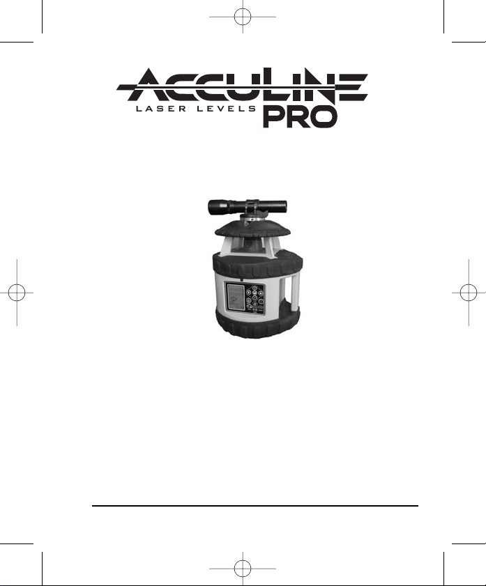
Electronic Self-Leveling Dual Grade Horizontal
Rotary Laser Level
Model No. 40-6580
Instruction Manual
Congratulations on your choice of this Electronic Self-Leveling Dual
Grade Horizontal Rotary Laser Level. We suggest you read this
instruction manual thoroughly before using the instrument. Save this
instruction manual for future use.
This is a Class IIIa laser tool and is manufactured to comply with CFR 21,
parts 1040 .10 and 1040 .11 as well as interna
©2009 Johnson Level & Tool 1
tional safety rule IEC 285.
Page 2

2406H 5/28/09 9:04 AM Page 2
Table of Contents
1. Kit Contents
2. Features and Functions
3. Safety Instructions
4. Location/Content
of Warning Labels
5. Location of Parts/Components
6. Operating Instructions
7. Using the Product
8. Accuracy Self-Check
9. Technical Specifications
10. Application Demonstrations
11. Care and Handling
12. Product Warranty
13. Product Registration
14. Accessories
1. Kit Contents
Description Model No. 40-6580 Qty.
Electronic Self-Leveling Dual Grade Horizontal Rotary Laser Level
Ni-MH Rechargeable Battery Pack 1
9V Battery Adapter 1
Remote Control with 9V Battery 1
Detector with 9V Battery and Clamp 1
Sighting Scope 1
Instruction Manual with Warranty Card 1
Hardshell Carrying Case 1
2. Features and Functions
• Large ±5° electronic auto-level range. When beyond the leveling
range, the laser beam will flash, rotation of the beam will stop, and
an audible alarm will activate.
• Electronic beam shield to turn the laser beam off in one to three
quadrants, when multiple lasers are being used.
• Programmable dual slope operation function allows user to
perform slope at different inclinations in both x and y axis.
• Height of Instrument/Tilt alarm function ensures product accuracy.
• Dust and rain resistant.
• Operates with Remote control.
• LCD display with backlight illumination.
• Adjustable rotation speeds of 0, 300, 600 and 1100 rpms.
1
2 ©2009 Johnson Level & Tool
Page 3
2406H 5/28/09 9:04 AM Page 3
3. Safety Instructions
Please read and understand all of the following instructions, prior
to using this tool. Failure to do so, may result in bodily injury.
DANGER!
Class IIIa Laser Product
Max. Power Output: ≤ 5mW
Wavelength: 625-645nm
THIS TOOL EMITS LASER RADIATION.
DO NOT STARE INTO BEAM.
AVOID DIRECT EYE EXPOSURE.
ATTENTION IMPORTANT
• Read all instructions prior to operating this laser tool. Do not remove any labels from tool.
• Do not stare directly at the laser beam.
• Do not project the laser beam directly into the eyes of others.
• Do not set up laser tool at eye level or operate the tool near a reflective surface as
the laser beam could be projected into your eyes or into the eyes of others.
• Do not place the laser tool in a manner that may cause someone to unintentionally
look into the laser beam. Serious eye injury may result.
• Do not operate the tool in explosive environments, i.e. in the presence of gases or
flammable liquids.
• Keep the laser tool out of the reach of children and other untrained persons.
• Do not attempt to view the laser beam through optical tools such as telescopes as
serious eye injury may result.
• Always turn the laser tool off when not in use or left unattended for a period of time.
• Remove the batteries when storing the tool for an extended time (more than 3 months)
to avoid damage to the tool should the batteries deteriorate.
• Do not attempt to repair or disassemble the laser tool. If unqualified persons attempt
to repair this tool, warranty will be void.
• Use only original AccuLine Pro
authorized dealer. Use of non-AccuLine Pro®parts and accessories will void warranty.
®
parts and accessories purchased from your AccuLine Pro
®
©2009 Johnson Level & Tool 3
Page 4
2406H 5/28/09 9:04 AM Page 4
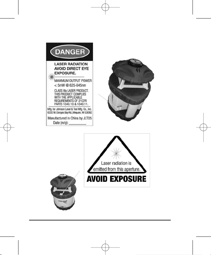
4. Location/Content of Warning Labels
4 ©2009 Johnson Level & Tool
Page 5
2406H 5/28/09 9:04 AM Page 5
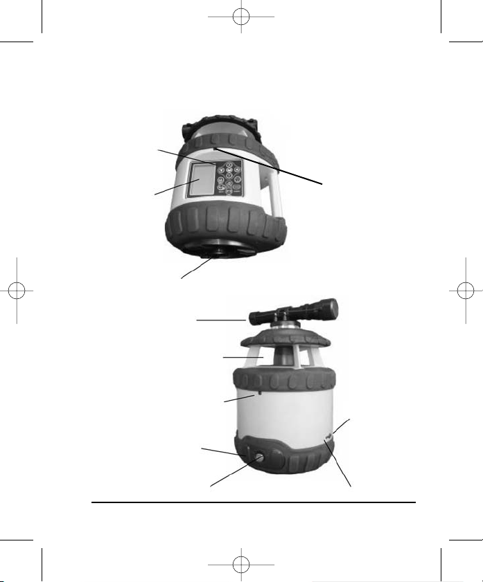
5. Location of Part/Components
Operating
Keypad
LCD Display
5/8” - 11 Screw Thread
Sighting Scope
Laser Output Window
Front Remote
Control Receiver
Back Remote
Control Receiver
Battery Cover
Battery Cover Screw
©2009 Johnson Level & Tool 5
Charging Port
Charging LED
Page 6
2406H 5/28/09 9:04 AM Page 6
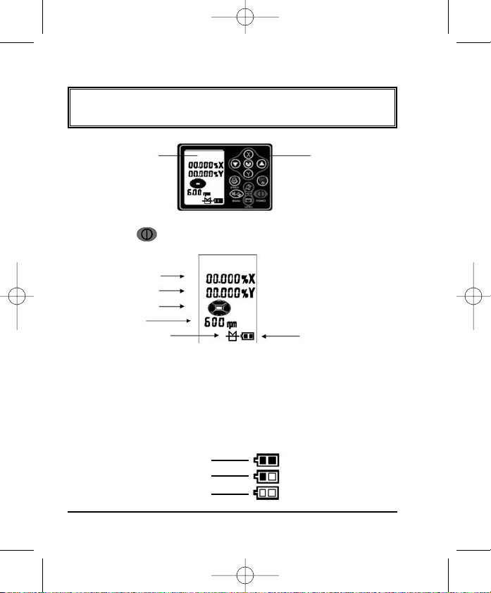
6. Operating Instructions
IMPORTANT: It is the responsibility of the user to verify the
calibration of the instrument before each use.
LCD Display
Operating Pad
Power On/Off:
Press the key to power on/off the instrument.
X-direction slope display
Y-direction slope display
Beam Shield section display
Rotate speed display
Auto-leveling status display
Battery capacity display
The instrument is in Auto-leveling status when powered on.
Default rotate speed is 600 rpm;
Default beam shield is off in all four quadrants;
Default grade for X-axis and Y-axis is 0.
When powered on, the instrument will automatically check the battery
capacity and show the following status.
Full Battery
Low Battery
Very Low Battery
6 ©2009 Johnson Level & Tool
Page 7
2406H 5/28/09 9:04 AM Page 7
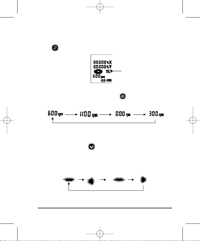
When powering on the instrument it will enter into the Auto-leveling mode.
30 seconds after the instrument begins to rotate, the instrument will enter
into the TILT mode and the LCD will show the following. Pressing the tilt
keypad prior to the Tilt display will result in no response.
Adjust Rotation Speed
Switch rotation speed by pressing the key . The LCD will show
the corresponding rotation speeds.
Beam Shield Mode
When turning on the laser, the beam shield will be off in all four
quadrants. Press the key to select the quadrant to be shielded.
The corresponding quadrant on the LCD will flash.
The order for selecting shield quadrant to be shielded:
Tilt mode
Y+ X+ Y- X-
©2009 Johnson Level & Tool 7
Page 8
2406H 5/28/09 9:04 AM Page 8
Press the key to add or remove the shield quadrant.
Press the key and the shield quadrant display is meaning
this quadrant will shield the laser beam.
Press the key and the shield quadrant display is meaning
quadrant will not shield the laser beam.
Press the key to activate the established shield display.
Note:
1. One, two or three quadrants can be shielded from the laser beam
simultaneously
.
2. Before pressing the key , only these four keys
and the power key are enabled, the other keys are disabled.
3. At 0 rpm, the beam shield mode is disabled. Pressing the key
will result without a response.
Tilt Function
After the laser has been turned on, has self-leveled and has rota
30 seconds, the Tilt display will be shown on the LCD. Pushing the
key prior to the tilt display will not produce a result.
Press the Tilt key to enter or exit the TILT mode, the LCD shows
the sign “TILT”.
ted for
Tilt function
8 ©2009 Johnson Level & Tool
Page 9
2406H 5/28/09 9:04 AM Page 9
If the instrument is bumped in the “TILT” mode, the instrument will
stop rotating, the laser will flash and the LCD sign “TILT” will begin
blinking. Press the key to have the instrument auto-leveling.
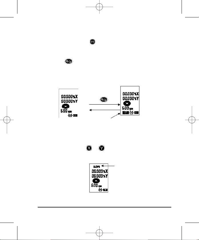
Manual Mode
Press the key to enter or exit manual mode. The LCD shows the
“MAN” when in manual mode. When entering the “MAN”
sign
status, the instrument will not auto-level. If the Tilt key is pressed
in “MAN” mode, the instrument will re-enter auto-leveling mode.
Press key
Auto-level mode
“MAN” status
Manual mode
Slope Setting
“SLOPE” setting range:
-7.999% to +7.999%
With the press of the key or , the instrument enters “SLOPE”
mode as shown in the following figure.
Slope setting
©2009 Johnson Level & Tool 9
Page 10

2406H 5/28/09 9:04 AM Page 10
X-direction SLOPE setting
Press the key once to make the first position in X-direction flash.
This position is the positive/negative slope position. Press the key
for positive slope indicated by a “O” sign. Press the key
for negative slope indicated by a “-” sign.
Press the key a second time to make the second position in X-
direction flash.
Press the key , the digit in this position increases to a maximum
of 7.
Press the key , the digit in this position decreases to a minimum
of 0.
Press the key a third time to make the third position in X-
direction flash.
Press the key , the digit in this position increases to a maximum
of 9.
Press the key , the digit in this position decreases to a minimum
of 0.
Press the key a fourth time to make the fourth position in X-
direction flash.
Press the key , the digit in this position increases to a maximum
of 9.
Press the key , the digit in this position decreases to a minimum of 0.
Press the key a fifth time to make the fifth position in X-direction
flash.
10 ©2009 Johnson Level & Tool
Page 11

2406H 5/28/09 9:04 AM Page 11
Press the key , the digit in this position increases to a maximum
of 9.
Press the key , the digit in this position decreases to a minimum
of 0.
Press the key a sixth time to repeat setting steps. When all the
digits are determined, press the key to enter the X-direction
grade setting.
Y-direction SLOPE Setting
Press the key to switch digital positions, the operation is the
same as the X-direction
“SLOPE” setting.
Note:
Before pressing the key only five keys for grade setting
and the power key are enabled. The other
keys are disabled.
After pressing the key the
“SLOPE” display on the LCD will flash.
While flashing all the keys are disabled except the power key.
Backlight
Press and hold the key for 2 seconds, the backlight on the
keypad can be turned on and off.
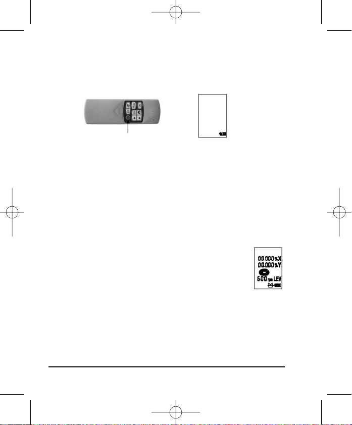
Remote Control Function
Most operations of the laser 40-6580
can be controlled by the remote
40-6747
control.
©2009 Johnson Level & Tool 11
Page 12
2406H 5/28/09 9:04 AM Page 12
Sleep Mode
Pressing the power key on the remote control will make the
instrument enter or exit the Sleep mode. When the instrument is
in Sleep mode, the LCD is shown as the following figure.
Power Key
Sleep mode
When the instrument is in Sleep mode, except for the power key, all
the other keys are disabled.
Note:
In the Sleep mode, the instrument will keep the current setting value.
When the instrument is turned on,
it will be in the same setting as
before entering Sleep mode.
All other remote key pad functions operate the same as the keypad
functions on the laser.
Beyond-tolerance Alarm
The auto-leveling range of the instrument is ±5°.
When the instrument is auto-leveling,
if the instrument is
tilted to exceed the auto-leveling range, it will give a
sound alarm, simultaneously the sign “LEV” on the LCD
will blink, as shown in the figure.
While the sign “LEV” is blinking, if the “X” sign is flashing, it means
the X-direction exceeds the auto-leveling range. If the “Y” sign is
flashing it means the Y-direction exceeds the auto-leveling range.
If the “X” and “Y” signs are flashing, it means the X-axis and Yaxis both exceed the auto-leveling range.
12 ©2009 Johnson Level & Tool
Page 13

2406H 5/28/09 9:04 AM Page 13
Note: The instrument will automatically power off if it is beyond its
self-leveling range for three minutes.
Application Methods
Install Ni-MH battery pack or alkaline batteries into the instrument,
or connect the instrument to the 9V DC
on a 5/8 x 11 tripod.
charger. Put the instrument
Connected to a 5/8 x 11 tripod
Connect the Sighting Scope
Note: If the instrument is tilted to exceed the auto-leveling range, it
will give a sound alarm.
Readjust the instrument.
Power on the instrument, and select your desired working status by
pressing the keys on the operating keypad or remote control.
Power off the instrument after operation or during movement.
©2009 Johnson Level & Tool 13
Page 14

2406H 5/28/09 9:04 AM Page 14
Detector Usage
Two-Sided Laser Detector with Clamp
Model No. 40-6715
The 40-6715 laser detector is an indispensable accessory when
using rotary laser levels. The main function of the detector is to
detect the position of the laser signals that are transmitted by rotary
lasers. This detection quickly and precisely provides the user with the
horizontal reference.
This product features high sensitivity, a double-faced display, low
power consumption, good reliability and easy manipulation. It can be
used with most types of rotating laser levels.
1. Technical Specifications
Detecting accuracy: Fine: ±0.039" (±1mm)
Automatic Shut-off: 6 minutes ±1 minute
Power Supply: 9V battery, 30 hrs continuous use
Sound indicator: slow short beep, rapid short beep and
LED display: down arrow, up arrow, horizontal on
Dimensions: 6.30" x 3.35" x 1.10" (160 x 85 x 28mm)
Weight: 1 lb. (0.45kg)
Others: Rain and dust resistant
14 ©2009 Johnson Level & Tool
Coarse 1: ±0.098" (±2.5mm)
when range ≥ 492 ft. (150m)
Coarse 2: ±0.394" (±10mm)
when range ≥ 492 ft. (150m)
(with LCD illumination off)
continuous sound
grade bar
Page 15

2406H 5/28/09 9:04 AM Page 15
2. Components
(a) Exterior Instruction
(b) Display
1. Power on symbol
2. Low battery indicator
3. Fine/Coarse symbol
4. Beeper symbol
5. Position indication arrows
Power Key: Turn on/off the power
1) Horizontal vial
2) Front display window
3) Front on grade mark
4) Vertical vial
5) LED key
6) Power key
7) Beeper
8) Reception window
9) Fine/Coarse accuracy key
10) Beeper key
11) Back display window
12) Back on grade mark
13) Bracket screw thread
14) Battery cover screw
15) Battery cover
Fine/Coarse Accuracy Key: Switch detecting accuracy
LED Key: Turn on/off the LCD’s light
Volume Key: Cycles between high, low and off
©2009 Johnson Level & Tool 15
Page 16

2406H 5/28/09 9:04 AM Page 16
3. Operation Guide
(a) Battery Installation
• Open the battery cover door by turning the battery cover screw
counter-clockwise. Put the battery into the
battery case noting the polarity shown in
the battery compartment.
• Put the battery cover door back, and tighten
the screw.
Note: 1) Remove the battery when the unit is being stored for a
long time.
When the low battery indicator is displayed, change the
2)
battery soon.
4. Operating Instructions
Power On
Press the power key to turn the unit on. The
LCD display will illuminate all the indicator
segments for 0.5 second (F
ig.2). When the
indicator segments are no longer
illuminated, the detector is ready for use.
Note: The LCD display will still have the
wer, detection and sound indicators illuminated (Fig. 3).
po
Figure 2
Figure 3
16 ©2009 Johnson Level & Tool
Page 17

2406H 5/28/09 9:04 AM Page 17
Fine/Coarse accuracy key
Power on and press the
fine/coarse accuracy key, the
unit will cycle between three
accuracy options: fine, coarse
1, coarse 2. The accuracy
symbol displayed on the LCD will change.
Volume Key
Power on and press the volume
, the unit will cycle between a
key
high sound, low sound and mute.
The sound symbol displayed on the LCD will change accordingly.
Note: There will be two beeps when turning the unit on and off.
There will be one beep when changing functions.
Detecting Laser Level Signals
While detecting laser signals, the LCD will display as follo
the set-up state of high sound and fine detection as an example)
Laser signal
Laser signal
ws: (take
Laser signal
The laser signal is down
Sound: rapid short beeps
©2009 Johnson Level & Tool 17
The laser signal is up
Sound: slow short beeps
Horizontal bar indicated on-grade
Sound: continuous sound
No laser signal is detected
Sound:
no sound
Page 18

2406H 5/28/09 9:04 AM Page 18
When the laser signal is near the on-grade mark, the displayed up
and down arrows will decrease as the distance to the on-grade mark
decreases.
Laser signal Laser signal Laser signal Laser signal
1. When detecting a horizontal laser signal, it is
important to have the bubble vial centered, as the
deflection of the receiver will influence its receiving
accuracy.
2. When detecting a vertical laser signal, it is important
to have the bubble vial centered, as the deflection of
the receiver will influence its receiving accuracy.
3. Keep the reception window facing the laser while detecting.
4. Hold the unit stable while detecting.
LED Function
Power on and press the LED key, the LCD will now be backlit.
Automatic Shut-off Function
When the unit does not receive a laser signal for 6 minutes, the
unit will power off automatically.
Low Battery Display Function
When the battery sign blinks on the LCD, the battery is
low and needs to be replaced. If the ba
ttery is very low,
the unit will power off automatically. Replace the battery.
18 ©2009 Johnson Level & Tool
Page 19

2406H 5/28/09 9:04 AM Page 19
Rod Clamp
Connecting to the rod clamp.
Connecting to the grade rod.
5. Detector Maintenance
• Keep the unit, particularly the reception window, clean. If it does get dirty,
use a cloth to wipe it clean.
©2009 Johnson Level & Tool 19
Page 20

2406H 5/28/09 9:04 AM Page 20
7. Using the Product
Ni-MH Battery
The 40-6580 is equipped with a large-capacity battery compartment
available for both Ni-MH batteries and 4 “D” alkaline batteries.
Battery Plug
Rechargeable Batteries Screw the battery cover loose and
Install the battery pack and insert
the battery plug.
open the ba
Replace the battery cover and
tighten the battery cover screw.
ttery cover
Alkaline Batteries
4 “D” Alkaline Batteries
Positive
Install alkaline batteries into the battery
compartment noting the polarity of batteries
20 ©2009 Johnson Level & Tool
Negative
Replace the battery cover and
tighten the battery cover screw.
Page 21

2406H 5/28/09 9:04 AM Page 21
9V Adapter
Charging Port Plug
Unplug the charging port plug and insert the 9V adapter to supply
wer to the instrument. If there are rechargeable batteries in the
po
battery compartment, they will be charged by the 9V adapter. In the
course of charging, the charging LED displays red, after charging for
about eight hours, the LED will turn green, this means the batteries
have been fully charged. If there are alkaline batteries in the battery
compartment the LED will display green and the batteries will not
charge.
Note: After the batteries have been fully charged, keep charging for
another two hours to ensure its ca
for 12 hours is advised for the first charge of new battery pack.
The instrument can operate while the batteries are recharging.
pacity. Continuously charging
©2009 Johnson Level & Tool 21
Page 22

2406H 5/28/09 9:04 AM Page 22
8. Self-Check and Calibration
IMPORTANT: It is the responsibility of the user to verify the
calibration of the instrument before each use.
Accuracy Check
50’
1. Put the laser on a tripod 50’ away from the wall. Put the laser
on the tripod with X+ axis towards wall.
2. Power on and after self-leveling,
mark “A” on the wall where the detector indicates on grade with
the laser beam.
3. Turning the instrument 90º,Y+, X-, Y-, after the laser self-levels,
mark “B” for Y+, “C” for X- and “D” for Y- on the front wall. Make
sure points B, C, D are in the same vertical line as point A.
4. Measure the vertical distance between the highest and lowest
points between A, B, C, D and mark that “h”.
5. If “h” is less than 1/32”, the accuracy is good. If it is more than
1/32”, the accuracy is beyond its tolerance and the laser needs to
be recalibrated.
using the detector, make a
22 ©2008 Johnson Level & Tool
Page 23

2406H 5/28/09 9:04 AM Page 23
Re-calibration
Referencing the results of the self-check and using the “h” mark (the
mid-point between the highest and the lowest point among A, B, C, D).
1. Enter self-calibration mode
a. Power off the instrument and face the X-axis towards the wall.
b. Press button and button simultaneously.
Then release the power button while still pressing
the manual button. Release the manual button after
10 seconds. The laser will enter self-calibration
mode and the LCD is shown as figure.
2. X-axis calibration
a. Open the cover on the remote control as shown below.
Down cover
b. Press button to select the X-direction AUTO-calibration,
the LCD will display as the following figure. The
instrument will rotate and the laser beam line will
show on the wall.
c. Press the button to make the laser beam
line move up and downwards until it coincides with
the “h” mark.
d. Press the button to confirm the X-direction calibration
value. The laser will stop rotating and the X-axis calibration
sign will turn off.
Calibration area
©2009 Johnson Level & Tool 23
Page 24

2406H 5/28/09 9:04 AM Page 24
3. Y-axis calibration
a. Turn off the instrument and turn the instrument 90º and
make the Y-axis face the wall.
b. Repeat steps 2a-2d of the X-axis. The LCD will
show as the following figure when the Y-direction
self-calibration is selected.
c. Press the button to make the laser beam
line move up and downwards until it coincides with the “h”
mark.
d. Press the button to confirm the Y-direction calibration
value. The laser will stop rotating and the Y-axis calibration
sign will turn off.
4. Self-calibration confirmation
Press key after finishing re-calibration on both X and Y
axis. The re-calibration LED turns off and the value of the
re-calibration will be stored. The laser has now exited
re-calibration mode.
Note: In order to make the saved calibration effective, you must
wer off the instrument after calibration, and then power it
po
on again. Y-axis accuracy check is a necessity after the X-axis
calibration, and X-axis accuracy check is also a necessity after
the Y-axis calibration. Laser re-calibration will not be finished
until both X-axis and Y-axis accuracy meet the specifications.
24 ©2009 Johnson Level & Tool
Page 25

2406H 5/28/09 9:04 AM Page 25
9. Technical Specifications
Laser Wavelength 635nm±10nm
Laser Classification Class IIIa
Maximum Power Output ≤5mW
y ±1/16"/100 ft. (±1.5mm/30m)
Accurac
Exterior Range Up to 2000 ft. (600m) diameter
Remote Range Up to 200 ft. (60m) diameter with remote
Auto-Leveling Range ±5°
Grade Setting Single axis +7.999% to 7.999%
Double axis X + Y = 12.00%
Scan Speed 0, 300, 600, and 1100 rpm
Power Supply Rechargeable battery pack, or 9V adapter
Battery Life
Dimensions 8.66" x 8.66" x 11.02"
Weight 11 lbs. (5Kg)
Working Temperature 14°F to 113°F (-10°C to 45°C)
Center Screw Thread 5/8" – 11
IP Protection Class 66
©2009 Johnson Level & Tool 25
(included), or 4 “D” alkaline batteries (not
included)
Approx. 50 hours with rechargeable battery
pack (included), 100 hours with 4 “D” alkaline
batteries (not included)
(220 x 220 x 280mm)
Page 26

2406H 5/28/09 9:04 AM Page 26
10. Application Demonstrations
Squaring Leveling
Elevation
26 ©2009 Johnson Level & Tool
Grading
Set Forms
Page 27

2406H 5/28/09 9:04 AM Page 27
11. Care and Handling
• This laser unit is a precision tool that must be handled with care.
• Avoid exposing unit to shock vibrations and extreme temperatures.
• Before moving or transporting the unit, make sure that the unit is
turned off.
• Remove the batteries when storing the unit for an extended time
(more than three months) to avoid damage to the unit should the
batteries deteriorate.
• Always store the unit in its case when not in use.
• Avoid getting the unit wet.
• Keep the laser unit dry and clean, especially the laser output window.
Remove any moisture or dirt with a soft, dry cloth.
• Do not use harsh chemicals, strong detergents or cleaning solvents
to clean the laser unit.
©2009 Johnson Level & Tool 27
Page 28

2406H 5/28/09 9:04 AM Page 28
12. Product Warranty
Johnson Level & Tool offers a one year limited warranty on each its
products. You can obtain a copy of the limited warranty for a
Johnson Level & Tool product by contacting Johnson Level & Tool's
Customer Service Department as provided below or by visiting us
online at www.johnsonlevel.com. The limited warranty for each
product contains various limitations and exclusions.
Do not return this product to the store/retailer or place of purchase.
Required repair/calibration must be done by an authorized AccuLine
®
service center or Johnson Level & Tool's limited warranty, if
Pro
applicable, will be void and there will be NO WARRANTY. Contact our
Customer Service Department to obtain a Return Material
Authorization (RMA) number for return to an authorized service center.
Proof of purchase is required.
NOTE: The user is responsible for the proper use and care of the
product.
It is the responsibility of the user to verify the calibra
instrument before each use.
For further assistance, or if you experience problems with this product
that are not addressed in this instruction manual, please contact our
Customer Service Department.
In the U.S., contact Johnson Level & Tool’s Customer Service
Department at 800-563-8553.
In Canada, contact Johnson Level & Tool’s Customer Service
Department at 800-346-6682.
tion of the
28 ©2009 Johnson Level & Tool
Page 29

2406H 5/28/09 9:04 AM Page 29
13. Product Registration
Enclosed with this instruction manual you will find a warranty card to be
completed for product warranty registration. Product warranty registration
can also be completed online at our web site www.johnsonlevel.com.
You will need to locate the serial number for your product that is located
on the bottom of the unit. PLEASE NOTE THAT IN ADDITION TO ANY
THER LIMITATIONS OR CONDITIONS OF JOHNSON LEVEL &
O
TOOL'S LIMITED WARRANTY, JOHNSON LEVEL & TOOL MUST
HAVE RECEIVED YOUR PROPERLY COMPLETED WARRANTY CARD
WITHIN 30 DAYS OF YOUR PURCHASE OF THE PRODUCT OR ANY
LIMITED WARRANTY THAT MAY APPLY SHALL NOT APPLY AND
THERE SHALL BE NO WARRANTY.
14. Accessories
AccuLine Pro®accessories are available for purchase through
authorized AccuLine Pro dealers. Use of non-AccuLine Pro accessories
will void any applicable limited warranty and there will be NO WARRANTY.
If you need any assistance in locating any accessories, please contact
our Customer Service Department.
In the U.S., contact Johnson Level & Tool’s Customer Service
Department at 800-563-8553.
In Canada, contact Johnson Level & Tool’s Customer Service
Department at 800-346-6682.
©2009 Johnson Level & Tool 29
Page 30

2406H 5/28/09 9:04 AM Page 30
30 ©2009 Johnson Level & Tool
 Loading...