

Page 1
™
40-6540_6550 English 6/28/05 9:44 AM Page 1
Automatic-Leveling Rotary Laser Level
with GreenBrite™ Technology
Model Nos. 40-6540 and 40-6550
Instruction Manual
Congratulations on your choice of this Automatic-Leveling Rotary
Laser Level with GreenBrite Technology. We suggest you read this
instruction manual thoroughly before using the instrument. Save this
instruction manual for future use.
This tool emits one rotating laser beam plus one plumb beam and is
ideal for laying out indoor or outdoor construction projects. Since the
product is equipped with a laser beam detector, visibility of the beam
in various lighting conditions is not an issue.
This is a Class IIIa laser tool and is manufactured to comply with CFR 21,
parts 1040 .10 and 1040 .11 as well as international safety rule IEC 285.
©2005 Johnson Level & Tool 1
Page 2

40-6540_6550 English 6/28/05 9:44 AM Page 2
Table of Contents
1. Kit Contents
2. Features and Functions
3. Safety Instructions
4. Location/Content
of Warning Labels
5. Location of Parts/Components
6. Operating Instructions
7. Using the Product
8. Accuracy Self-Check
9. Technical Specifications
10. Application Demonstrations
11. Care and Handling
12. Product Warranty
13. Product Registration
14. Accessories
1. Kit Contents
Description Model No. 40-6540 Qty.
Automatic-Leveling Rotary Laser Level with GreenBrite™ Technology 1
Ni-MH Rechargeable Battery Pack 1
6V Battery Adapter 1
Remote Control with 9V Battery 1
Detector with 3 “AAA” Batteries and Quick Clamp 1
Magnetic Target 1
Tinted Glasses 1
Instruction Manual with Warranty Card 1
Hardshell Carrying Case 1
Description Model No. 40-6550 Qty.
Automatic-Leveling Rotary Laser Level with GreenBrite™ Technology 1
Ni-MH Rechargeable Battery Pack 1
6V Battery Adapter 1
Vertical Mounting Bracket 1
Multi-Function Mount with Carrying Case 1
Remote Control with 9V battery 1
Detector with 3 “AAA” Batteries with Quick Clamp 1
Magnetic Target 1
Tinted Glasses 1
Aluminum Tripod 1
8 ft. Grade Rod with Carrying Case 1
Instruction Manual with Warranty Card 1
Hardshell Carrying Case 1
2 ©2005 Johnson Level & Tool
Page 3
40-6540_6550 English 6/28/05 9:44 AM Page 3
2. Features and Functions
• Green beam is 400% brighter than red beam laser levels.
• Large electronic auto-level range: The unit works normally within
±5°. When beyond the ±5° leveling range, the laser line flashes,
rotation of the beam stops, and an audible alarm activates.
• Vertical and horizontal working modes: Unit projects one horizontal
plane/line and one plumb-up point or, when used with the vertical
mount, one plumb plane/line and one horizontal point.
• Adjustable laser rotating speed
• Scan function adjusts the scan line size and scan direction.
• Slope function allows user to perform the slope scan at different
inclinations.
• Dust and rain resistant
• Timed auto-off function
3. Safety Instructions
Please read and understand all of the following instructions, prior
to using this tool. Failure to do so, may result in bodily injury.
DANGER!
Class IIIa Laser Product
Max. Power Output: ≤ 5mW
Wavelength: 522-542nm
THIS TOOL EMITS LASER RADIATION.
DO NOT STARE INTO BEAM.
AVOID DIRECT EYE EXPOSURE.
©2005 Johnson Level & Tool 3
Page 4
40-6540_6550 English 6/28/05 9:44 AM Page 4
ATTENTION IMPORTANT
• Read all instructions prior to operating this laser tool. Do not remove any labels from
tool.
• Use of controls or performance of procedures other than those specified herein may
result in hazardous radiation exposure.
• Do not stare directly at the laser beam.
• Do not project the laser beam directly into the eyes of others.
• Do not set up laser tool at eye level or operate the tool near a reflective surface as
the laser beam could be projected into your eyes or into the eyes of others.
• Do not place the laser tool in a manner that may cause someone to unintentionally
look into the laser beam. Serious eye injury may result.
• Do not operate the tool in explosive environments, i.e. in the presence of gases or
flammable liquids.
• Keep the laser tool out of the reach of children and other untrained persons.
• Do not attempt to view the laser beam through optical tools such as telescopes as
serious eye injury may result.
• Always turn the laser tool off when not in use or left unattended for a period of time.
• Remove the batteries when storing the tool for an extended time (more than 3 months)
to avoid damage to the tool should the batteries deteriorate.
• Do not attempt to repair or disassemble the laser tool. If unqualified persons attempt
to repair this tool, serious injury may result.
• Use only original AccuLine Pro
Pro authorized dealer. Use of non-AccuLine Pro parts and accessories will void warranty.
CAUTION: If using this product with any type of tinted goggles,
please note safety warning below.
™
parts and accessories purchased from your AccuLine
WARNING!
The tinted goggles are designed to enhance
the visibility of the laser beam. They DO NOT
offer protection to the eyes from direct exposure
of the laser beam.
4 ©2005 Johnson Level & Tool
Page 5
40-6540_6550 English 6/28/05 9:44 AM Page 5
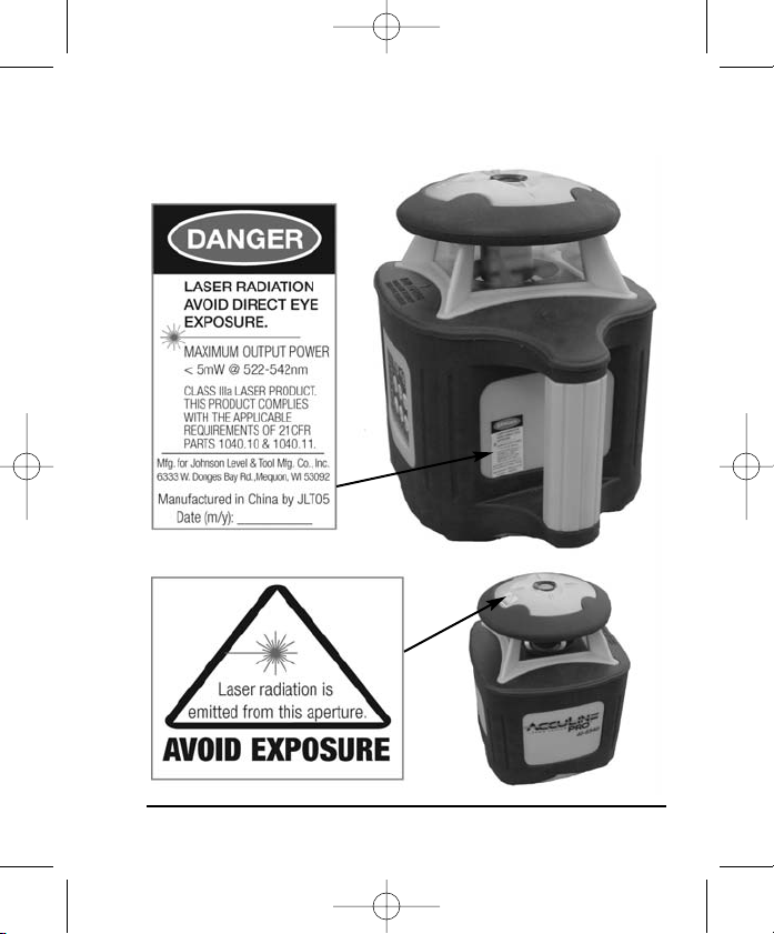
4. Location/Content of Warning Labels
©2005 Johnson Level & Tool 5
Page 6
40-6540_6550 English 6/28/05 9:44 AM Page 6
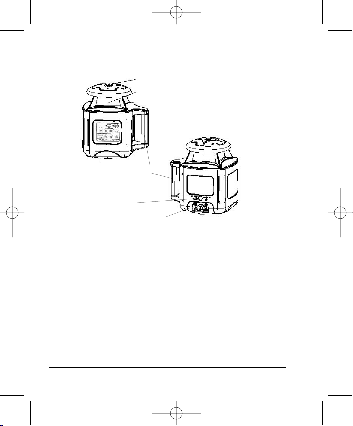
5. Location of Part/Components
Laser Point Output Window
Rotating Laser Output Window
Operation Panel
DC 6V Battery Plug
Battery Compartment Cover
Handle
6. Operating Instructions
IMPORTANT: It is the responsibility of the user to verify the calibration
of the instrument before each use.
Notes:
• Always check to make sure that the on/off switch is in the off
position (when power indicator lamp is not lit) before removing
and replacing batteries.
• Both Ni-MH and “C” alkaline batteries (not included) can be used
in the unit’s battery compartment.
• Unit ships with Ni-MH battery packs installed.
6 ©2005 Johnson Level & Tool
Page 7
40-6540_6550 English 6/28/05 9:44 AM Page 7
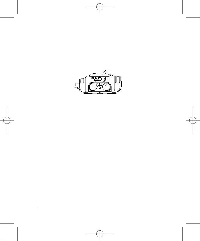
Alkaline Battery Installation
1. Remove battery compartment cover by loosening the bolt with a
coin. Remove the Ni-MH battery packs from the chambers inside
the battery compartment, making sure to disconnect the two-pin
connectors. Then, insert “C” alkaline batteries into the chambers,
noting polarity as shown on chamber bottoms or cover of battery
compartment.
Two-pin connector receptacles
Notes:
• When the battery case is filled with “C” alkaline batteries, the
power adapter should not be used to charge these batteries.
• Charging alkaline batteries can result in explosion.
• Used (discharged) batteries are hazardous waste and should be
disposed of properly.
Charging Ni-MH Rechargeable Batteries
1. Remove black rubber plug above the battery compartment cover
and insert the 6V battery adapter. Plug adapter into 115V AC wall
socket to begin charging. During the first charge of the batteries,
the charge indicator lamp is red. After 5 hours or so, the indicator
lamp will turn green showing that the battery pack has been fully
charged.
Notes:
(1) Even after battery pack appears to be full charged, we suggest
users continue to charge for 2 more hours to ensure the batterypack’s maximum charge capacity.
©2005 Johnson Level & Tool 7
Page 8
40-6540_6550 English 6/28/05 9:44 AM Page 8
(2) We also suggest charging a new battery during its initial charge
for at least ten hours.
(3) The instrument will still work even if it being charged with adapter.
Instrument Usage
1. Put in Ni-MH rechargeable battery pack, or 4 “C” alkaline batteries
(not included), or connect the 6V DC battery adaptor to the unit’s
power jack.
2. Place the instrument on a platform or tripod, connecting with tripod
to the 5/8" screw thread at the bottom of the instrument.
Note: If the instrument is inclined beyond the self-leveling range,
the instrument will deliver an audible alarm. You will need to
re-position the instrument until it can be leveled.
3. Press power switch to turn power on, and press operation buttons
on control panel or use remote control to adjust to your desired
working status.
4. After finishing operation or before moving the instrument, turn the
power off.
7. Using the Product
Place the unit on a relatively level surface like a table, floor, etc during
operation.
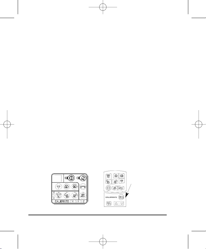
Operating
Panels
Instrument Panel
8 ©2005 Johnson Level & Tool
Remote Control Panel
operating panel for
calibration (located
beneath the sliding
nameplate panel of
the remote control) to
be used by service
personnel only
Page 9

40-6540_6550 English 6/28/05 9:44 AM Page 9
Note: Calibration buttons on instrument operation panel and remote
control panel must only be used by an authorized AccuLine Pro
™
service center.
Power On/Off
1. Press the power button to power on. The power indicator lamp
should light up and then the instrument will automatically level
itself, with rotation occurring once the unit is level.
2. Press the power button again to power off.
Low Battery Indicator
If the battery indicator lamp is lit, this means low battery
voltage. To ensure normal operation, replace batteries
or charge the rechargeable Ni-MH battery pack.
Alarm If Beyond Range
If the instrument is inclined beyond the auto-leveling range of ±5°, it will
deliver an audible alarm, and the power indicator lamp will flash. You
will need to re-position the instrument until it is within the leveling range.
Safety Mode (TILT)
1. After powering on the instrument and entering into auto-level status,
press the safety mode (TILT) button. When the indicator
lamp illuminates (see figure), the instrument enters
into safety mode.
2. If the leveled instrument is moved or bumped, the head will stop
rotation and the safety mode indicator lamp will flash instead of
the unit performing the auto-level function. At this
time, you must press the level vial button (see figure).
©2005 Johnson Level & Tool 9
Page 10

40-6540_6550 English 6/28/05 9:44 AM Page 10
The unit will re-level automatically and enter into primary working
status.
3. Press the safety mode (TILT) button again to quit safety mode and
activate auto-level mode.
Speed Adjustment
After unit automatically-levels, it rotates at its highest speed.
Press the speed adjustment button (see figure) to change the
rotating speed.
Note: During the auto-leveling sequence, this key is not functional.
Range Scan Mode
1. Press the range scan mode button (see figure) to activate
range scan mode.
2. With the second press of this button, the unit emits a long bright
laser line.
3. With the third press of this button, the unit emits a bright laser point.
4. To return to rotating, press the speed adjustment button.
Adjusting the Scan Range
1. Press the first button to the right of the range
scan mode button and the scan area moves counter-clockwise.
2. Press the second button to the right of the range scan mode button
and the scan area moves clockwise.
Slope Adjusting Function
1. Press the slope adjusting mode button (see figure) to enter
into the slope setting mode and select X direction slope.
- Press the first button to the right of the slope adjusting mode
button to shift the slope angle to the left.
10 ©2005 Johnson Level & Tool
Page 11

40-6540_6550 English 6/28/05 9:44 AM Page 11
- Press the second button to the right of the
slope adjusting mode button to shift the
slope angle to the right.
2. Press the slope adjusting mode button again to select Y direction slope.
- Press the first button to the right of the slope adjusting mode
button to shift the slope angle to the left.
- Press the second button to the right of the slope adjusting mode
button to shift the slope angle to the right.
3. Another press of the slope adjusting mode button changes back to
X direction slope selection. However, pressing and holding the button
returns the unit to normal operation.
Notes:
• When the unit is in safety mode, press the slope adjusting mode
button to exit from the safety mode and into the slope adjusting mode.
• Using the unit in the vertical position, the X direction slope can be
adjusted while the Z direction slope is automatically adjusted. This
means that the horizontal laser point is in a fixed, level (Z) position
but can be adjusted to the left or right.
• In the vertical position, the unit cannot rotate or enter into range
scan mode immediately. It must first be level in the Z direction
before you can select rotation or range scan mode.
• The maximum adjusting angle is 5 degrees.
Timed Auto-off Function
Turn the unit on using the power button on the instrument operating
panel. Then, press the power button once on the remote control. The
unit is now in sleep mode.
If the unit is in sleep mode for 30 continuous minutes, the unit turns off
©2005 Johnson Level & Tool 11
Page 12

40-6540_6550 English 6/28/05 9:44 AM Page 12
automatically. With a second press of the power button on remote control,
the unit exits sleep mode and enters auto-level mode.
Using the Vertical Mounting Bracket
The vertical mounting bracket allows the unit to be used in the
vertical position on a table or tripod, but it can also be hung on a wall
for horizontal leveling (see drop ceiling application drawing example
on page 22).
To use the unit with the vertical mounting bracket (see figure):
Locking knob
Circular bull’s-eye level vial
Leveling knobs
1. Place the unit on its side with the handle up and the bottom facing
the bracket surface with the locking-knob. Attach the bracket to
the unit by screwing the locking knob thread into the base of the
unit.
2. Adjust the two leveling knobs on the base of the vertical mounting
bracket so that the bubble of the circular bull’s-eye level vial
(located on top of vertical mounting bracket) is centered.
12 ©2005 Johnson Level & Tool
Page 13

40-6540_6550 English 6/28/05 9:44 AM Page 13
Detector Usage
Note: This green laser level uses a specific detector for the green
beam and will not perform accurately with standard detectors.
1. Product Description
A laser detector is an indispensable accessory when using rotary laser
levels. The main function of the detector is to locate the position of
laser signals transmitted by rotary lasers. This detection quickly and
precisely provides the user with the horizontal and vertical references.
This product features a high level of sensitivity, a double-faced display,
low power consumption, good reliability and easy manipulation.
2. Technical Specifications
Detecting range ≥656 ft. (200m)
Detecting accuracy Fine ±0.08" (±2mm) when range is < 492 ft. (150m)
Turn-off time 6 minutes ±1 minute
Power DC 3.3V or 3 “AAA” batteries
Sound indicator slow short sounds, rapid short sounds
LED indicator up, mid, down
Dimensions 7.087" x 3.228" x 0.236" (180 x 82 x 26mm)
Weight 0.485 lb. (220g)
Others Rain and dust resistant
Coarse ±0.16" (+4mm) when range is < 492 ft. (150m)
Fine ±0.12" (±3mm) when range is > 492 ft. (150m)
Coarse ±0.24" (+6mm) when range is > 492 ft. (150m)
and a continuous sound
©2005 Johnson Level & Tool 13
Page 14

40-6540_6550 English 6/28/05 9:44 AM Page 14
3. Components
(a) Structure
1) Horizontal vial
2) Right-faced display window
3) Lineation slot
4) Receiving window
5) Power button
6) Buzzer
7) Battery-box
8) Sound switch
9) Coarse/Fine detection switch
10) Illumination switch
11) Mounting hole
12) Battery installation symbol
13) Scale
(b) Display
1. Power indicator
2. Low battery indicator
3. Detection indicator
4. Sound indicator
5. Detected position (grade) indicator
14 ©2005 Johnson Level & Tool
Page 15

40-6540_6550 English 6/28/05 9:44 AM Page 15
4. Operation Guide
(a) Battery Installation
1) Rotate battery-box cap counterclockwise to open it. (A coin fits
easily into this slot.)
2) Insert 3 AAA batteries (note polarity) and then rotate battery-box
cap clockwise to close it.
3) When the battery voltage is low, the unit will display a low battery
indicator and there will be a buzzing “reminder” sound every 2-4
seconds. You will still be able to use the instrument for a short
period of time, but should change the battery soon. (Note: When
the low battery indicator is displayed, the illumination function
cannot be used. (See “Using the Illumination Function.)
Note:
a) Remove the batteries when the unit is being stored for a long time.
b) When the low battery indicator is displayed, change the battery soon.
c) Turning off the sound and illumination functions will allow you
to use the unit longer.
(b) General Detector Usage
Always keep the instrument stable when detecting.
Note:
1) Press the power key to turn the unit
on. The LCD display will illuminate all
the indicator segments for 0.5 second
(Fig. 6). When the indicator segments
are no longer illuminated, the detector
is ready for use. Note: The LCD display
will still have the power, detection and
sound indicators illuminated (Fig. 7).
Fig. 6 Fig. 7
©2005 Johnson Level & Tool 15
Page 16

40-6540_6550 English 6/28/05 9:44 AM Page 16
2) Detecting horizontal laser level signals
• Place the unit in a vertical position (verify by checking the horizontal
vial bubble).
• Make sure the receiving window (on front of detector) is facing the
laser level unit and is receiving the laser signal.
- If the LCD shows a “down” arrow and emits rapid short sounds, this
indicates that the laser level signal is located below the detector (Fig. 8).
- If the LCD shows an “up” arrow and emits slow short sounds, this
indicates that the
laser level signal is
located above the
detector (Fig. 9).
- If the LCD shows the
“center” mark and
emits a continuous
Fig. 8 Fig. 9 Fig. 10-1 Fig. 10-2
sound, this indicates that the laser level signal is located in the center
position on the detector.
(Fig. 10-1) LCD indicating center position of coarse detection
(Fig. 10-2) LCD indicating center position of fine detection
Note: As the laser signal gradually nears the center position on the
detector, the arrow displayed will decrease in length until just the
center position signal is displayed (Fig. 11, 12, 13-1, 13-2).
Fig. 11 Fig. 12 Fig. 13-1 Fig. 13-2
16 ©2005 Johnson Level & Tool
Page 17

40-6540_6550 English 6/28/05 9:44 AM Page 17
3) Detecting vertical laser level signals
• Place the unit in a horizontal position.
• Make sure the receiving window (on front of detector) is facing
the laser level unit and is receiving the laser signal.
- If the LCD shows a “left” arrow and emits rapid
short sounds, this indicates that the laser level
signal is located to the right of the detector (Fig. 14).
- If the LCD shows a “right” arrow and emits
slow short sounds, this indicates that the laser
level signal is located to the left of the detector
(Fig. 15).
- If the LCD show the “center” mark and emits a
continuous sound, this indicates that the laser
level signal is located in the center position on
the detector.
(Fig. 16-1) LCD indicating center position
Fig. 16-1
of coarse detection
(Fig. 16-2) LCD indicating center position of fine
detection
Fig. 16-2
4) When you are finished using the detector, press the power key to
turn the unit off.
Fig. 14
Fig. 15
(c) Using the Sound Function
With the detector turned ON, press the
Sound
Silence
sound switch to alternate between
sound-on and sound-off.
Fig. 17 Fig. 18
Note: The sound indicator will also turn on and off in the
LCD screen (Fig. 17, 18).
©2005 Johnson Level & Tool 17
Page 18

40-6540_6550 English 6/28/05 9:44 AM Page 18
With the sound function turned on:
- If the laser signal is above the detector, a slow short sound is emitted.
- If the laser signal is below the detector, a rapid short sound is emitted.
- If the laser signal is aligned on the mid portion of the detector, a
continuous sound is emitted.
Note: Whether or not the sound function is in use, there is still indicator
sound when you press the key.
(d) Using the Coarse/Fine Detecting Switch
With the detector turned ON, press the coarse/
fine switch. This switch alternates the unit
between coarse and fine detecting. The detector
has different check and measure precision.
(Fig. 19) LCD indicating coarse detection
(Fig. 20) LCD indicating fine detection
Fig. 19 Fig. 20
(e) Using the Illumination Function
With the detector turned ON, press the illumination switch. This
switch turns the background illumination of the LCD on and off.
(f) Power Saving Function
When the instrument cannot receive the laser signal for 6 continuous
minutes, and there is no detection occurring during this 6 minutes,
the unit will shut off automatically to prolong the battery’s life.
18 ©2005 Johnson Level & Tool
Page 19

40-6540_6550 English 6/28/05 9:44 AM Page 19
(g) Low Battery Indicator
If the LCD shows a blinking battery sign, it is indicating that you have low charge on your batteries and
that you need to change them soon (Fig. 21).
If the battery power is too low, the instrument will shut
off automatically. At this time, you must change the
batteries in order to continue using the detector.
5. Detector Maintenance
• When you are done using the detector, return it to its packing case.
• Keep the instrument, particularly the detecting window, clean.
If unit becomes dusty, use a clean cloth to gently wipe it clean.
• Avoid knocking the unit over or allowing it to fall on the ground.
• Although the instrument is rain resistant, you should avoid
submerging the unit in water or other liquids. If unit comes
into contact with water or other liquids, wipe it dry immediately.
• Do not use unit around fire or expose it to fire in any way.
Blink
Fig. 21
©2005 Johnson Level & Tool 19
Page 20

40-6540_6550 English 6/28/05 9:44 AM Page 20
8. Accuracy Self-Check
1. Set up the instrument on a table 65 ft. (20m) away from an indoor
wall, with one of the X-axes facing the wall as indicated by the
“X” marked on the top of the unit.
2. Press the power button to turn the unit on. After the unit auto-levels,
press the range scan button (on either the unit or the remote control)
to put the unit in range scan mode.
3. Press the range scan button two more times to emit a bright laser point.
4. Mark the center of this point on the wall and label it as point “A”.
5. Rotate the unit clockwise by 90 degrees and use the second button
to the right of the range scan button to jog the laser point back
toward the wall and the point marked as “A”.
Note: The laser points might not line up exactly on the same
horizontal plane, but they should be on the same vertical plane
(i.e., in a straight vertical line).
6. Mark the center of this second point on the wall and label it as
point “B”.
7. Repeat steps 5 and 6, marking centers of new points “C” and “D”.
8. Now, measure the distance between the highest and lowest points.
This measurement = “h”.
Note: The maximum distance between any two points should not
exceed the stated accuracy of ≤0.157" (4mm).
Wall
20 ©2005 Johnson Level & Tool
Page 21

40-6540_6550 English 6/28/05 9:44 AM Page 21
9. If h ≤0.157" (4mm), the unit’s accuracy is within tolerance.
If h >0.157" (4mm), but <0.394" (10mm), OR h
please reference Section 12 of this document.
Note: The above procedure using a distance of 65 ft. (20m) from a
wall is suggested due to the difficulty of precisely marking the center
of laser points at shorter distances.
≥0.394" (10mm),
9. Technical Specifications
Laser Wavelength 532nm±10nm
Laser Classification Class IIIa
Maximum Power Output
Accuracy Horizontal Rotation = ±1/8"/100 ft.
Working Range Maximum 100 ft. (30m),
Measuring Range 656 ft. radius (200m) with detector
Auto-Leveling Range ±5° (delivers an alarm if beyond range, and
Power Supply 4 “C” alkaline batteries (not included),
Dimensions 7.4" x 5.91" x 8.15" (188 x 150 x 207mm)
Weight 5.512 lbs. (2.5Kg)
Working Temperature 32°F to 104°F (0°C to 40°C)
Center Screw Thread 5/8" – 11
Rotation Speeds 200 and 600 rpm
Range Scan Area Continuous, small range, large range, point
Enclosure Dust and rain resistant
©2005 Johnson Level & Tool 21
≤5mW
(±0.1mm/10m)
Vertical Rotation = ±3/16"/100 ft.
(±1.5mm/10m)
depending upon light conditions
33 ft. (10m) with remote
stops rotation simultaneously)
rechargeable battery pack,
or 6V adapter (included)
Page 22

40-6540_6550 English 6/28/05 9:44 AM Page 22
10. Application Demonstrations
Plumb reference for ceiling
installation
Reference for window installation
Reference for squaring and
leveling
Reference for fence and retailing
wall construction
22 ©2005 Johnson Level & Tool
Reference for anti-static flooring
installation
Reference for flooring
Reference for cement floor
installation
Reference for grading
Page 23

40-6540_6550 English 6/28/05 9:44 AM Page 23
11. Care and Handling
• This laser unit is a precision tool that must be handled with care.
• Avoid exposing unit to shock vibrations and extreme temperatures.
• Before moving or transporting the unit, make sure that the unit is turned off.
• Remove the batteries when storing the unit for an extended time (more than
three months) to avoid damage to the unit should the batteries deteriorate.
• Always store the unit in its case when not in use.
• Avoid getting the unit wet.
• Keep the laser unit dry and clean, especially the laser output window.
Remove any moisture or dirt with a soft, dry cloth.
• Do not use harsh chemicals, strong detergents or cleaning solvents to clean
the laser unit.
12. Product Warranty
Johnson Level & Tool offers a one year limited warranty on each its products.
You can obtain a copy of the limited warranty for a Johnson Level & Tool product
by contacting Johnson Level & Tool's Customer Service Department as provided
below or by visiting us online at www.johnsonlevel.com. The limited warranty
for each product contains various limitations and exclusions.
Do not return this product to the store/retailer or place of purchase. Required
repair/calibration must be done by an authorized AccuLine Pro™ service center
or Johnson Level & Tool's limited warranty, if applicable, will be void and there
will be NO WARRANTY. Contact our Customer Service Department to obtain a
Return Material Authorization (RMA) number for return to an authorized service
center. Proof of purchase is required.
NOTE: The user is responsible for the proper use and care of the product. It is the
responsibility of the user to verify the calibration of the instrument before each use.
For further assistance, or if you experience problems with this product that are not
addressed in this instruction manual, please contact our Customer Service Dept.
In the U.S., contact Johnson Level & Tool’s Customer Service Department at
800-563-8553.
In Canada, contact Johnson Level & Tool’s Customer Service Department at
800-346-6682.
©2005 Johnson Level & Tool 23
Page 24

40-6540_6550 English 6/28/05 9:44 AM Page 24
13. Product Registration
Enclosed with this instruction manual you will find a warranty card to be
completed for product warranty registration. Product warranty registration
can also be completed online at our web site www.johnsonlevel.com.
You will need to locate the serial number for your product that is located
on the bottom of the unit.
OTHER LIMITATIONS OR CONDITIONS OF JOHNSON LEVEL &
TOOL'S LIMITED WARRANTY, JOHNSON LEVEL & TOOL MUST
HAVE RECEIVED YOUR PROPERLY COMPLETED WARRANTY CARD
WITHIN 30 DAYS OF YOUR PURCHASE OF THE PRODUCT OR ANY
LIMITED WARRANTY THAT MAY APPLY SHALL NOT APPLY AND
THERE SHALL BE NO WARRANTY
PLEASE NOTE THAT IN ADDITION TO ANY
.
14. Accessories
AccuLine Pro™ accessories are available for purchase through
authorized AccuLine Pro dealers. Use of non-AccuLine Pro accessories
will void any applicable limited warranty and there will be NO WARRANTY.
If you need any assistance in locating any accessories, please contact
our Customer Service Department.
In the U.S., contact Johnson Level & Tool’s Customer Service
Department at 800-563-8553.
In Canada, contact Johnson Level & Tool’s Customer Service
Department at 800-346-6682.
24 ©2005 Johnson Level & Tool
 Loading...