

Page 1
®
1467H-English 8/6/08 10:07 AM Page 1
Electronic Self-Leveling Horizontal
Rotary Laser Level
Model No. 40-6537
Instruction Manual
Congratulations on your choice of this Electronic Self-Leveling
Horizontal Rotary Laser Level. We suggest you read this instruction
manual thoroughly before using the instrument. Save this instruction
manual for future use.
This is a Class IIIa laser tool and is manufactured to comply with CFR 21,
parts 1040 .10 and 1040 .11 as well as international safety rule IEC 285.
©2008 Johnson Level & Tool 1
Page 2

1467H-English 8/6/08 10:07 AM Page 2
Table of Contents
1. Kit Contents
2. Features and Functions
3. Safety Instructions
4. Location/Content
of Warning Labels
5. Location of Parts/Components
6. Operating Instructions
7. Using the Product
8. Accuracy Self-Check
9. Technical Specifications
10. Application Demonstrations
11. Care and Handling
12. Product Warranty
13. Product Registration
14. Accessories
1. Kit Contents
Description Model No. 40-6537 Qty.
Electronic Self-Leveling Horizontal Rotary Laser Level
Ni-MH Rechargeable Battery Pack 1
6V Battery Adapter 1
Remote Control with 9V Battery 1
Detector with 9V Battery and Quick Clamp 1
6 “AA” Battery Holder 1
Instruction Manual with Warranty Card 1
Hardshell Carrying Case 1
2. Features and Functions
• Large ±5° electronic auto-level range. When beyond the leveling
range, the laser line will flash, rotation of the beam will stop, and an
audible alarm will activate.
• Electronic beam shield to turn the laser beam off from one to three
quadrants for multiple laser usage.
• Vibrate mode ignores slight movements as in windy conditions.
• Slope operation function allows user to perform slope at
different inclinations in both x and y axis.
• Height of Instrument (H.I.) alarm function ensures product accuracy.
• Projects a laser horizontal plane.
• Dust and rain resistant.
• Remote power off function.
• Included detector and remote control for more convenient operation.
2 ©2008 Johnson Level & Tool
1
Page 3
1467H-English 8/6/08 10:07 AM Page 3
3. Safety Instructions
Please read and understand all of the following instructions, prior
to using this tool. Failure to do so, may result in bodily injury.
DANGER!
Class IIIa Laser Product
Max. Power Output: ≤ 5mW
Wavelength: 625-645nm
THIS TOOL EMITS LASER RADIATION.
DO NOT STARE INTO BEAM.
AVOID DIRECT EYE EXPOSURE.
ATTENTION IMPORTANT
• Read all instructions prior to operating this laser tool. Do not remove any labels from tool.
• Do not stare directly at the laser beam.
• Do not project the laser beam directly into the eyes of others.
• Do not set up laser tool at eye level or operate the tool near a reflective surface as
the laser beam could be projected into your eyes or into the eyes of others.
• Do not place the laser tool in a manner that may cause someone to unintentionally
look into the laser beam. Serious eye injury may result.
• Do not operate the tool in explosive environments, i.e. in the presence of gases or
flammable liquids.
• Keep the laser tool out of the reach of children and other untrained persons.
• Do not attempt to view the laser beam through optical tools such as telescopes as
serious eye injury may result.
• Always turn the laser tool off when not in use or left unattended for a period of time.
• Remove the batteries when storing the tool for an extended time (more than 3 months)
to avoid damage to the tool should the batteries deteriorate.
• Do not attempt to repair or disassemble the laser tool. If unqualified persons attempt
to repair this tool, warranty will be void.
• Use only original AccuLine Pro
authorized dealer. Use of non-AccuLine Pro®parts and accessories will void warranty.
®
parts and accessories purchased from your AccuLine Pro
®
©2008 Johnson Level & Tool 3
Page 4
1467H-English 8/6/08 10:07 AM Page 4
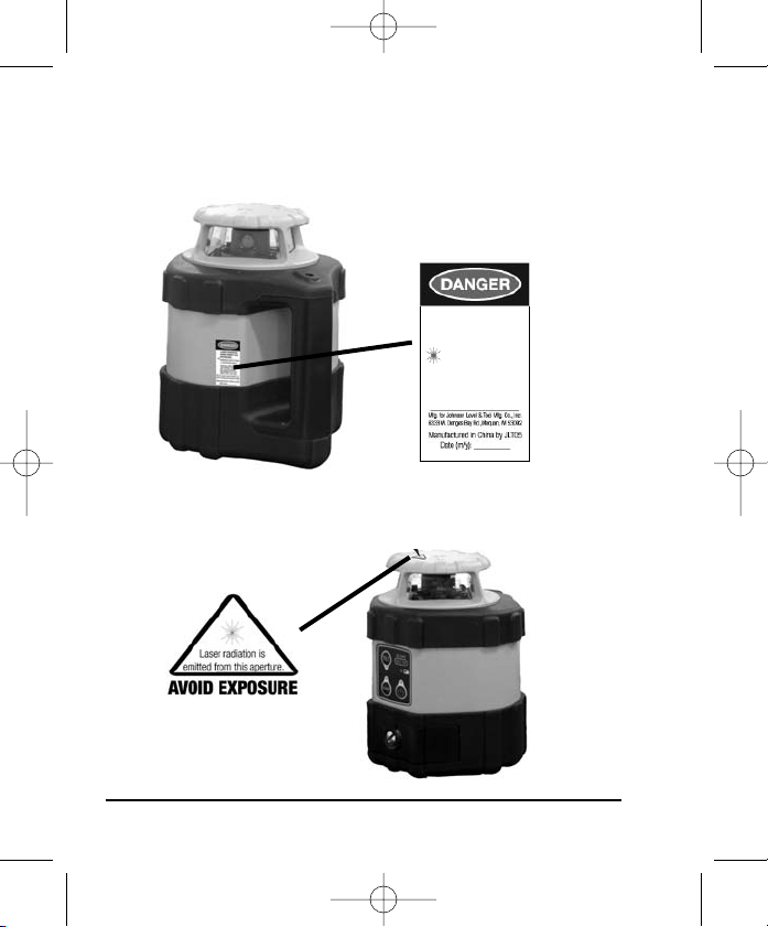
4. Location/Content of Warning Labels
LASER RADIATION
AVOID DIRECT EYE
EXPOSURE.
MAXIMUM OUTPUT POWER
≤ 5mW @ 625-645nm
CLASS
IIIa LASER PRODUCT.
THIS PRODUCT COMPLIES WITH
THE APPLICABLE REQUIREMENTS OF 21 CFR PARTS
1040.10 & 1040.11
4 ©2008 Johnson Level & Tool
Page 5
1467H-English 8/6/08 10:07 AM Page 5
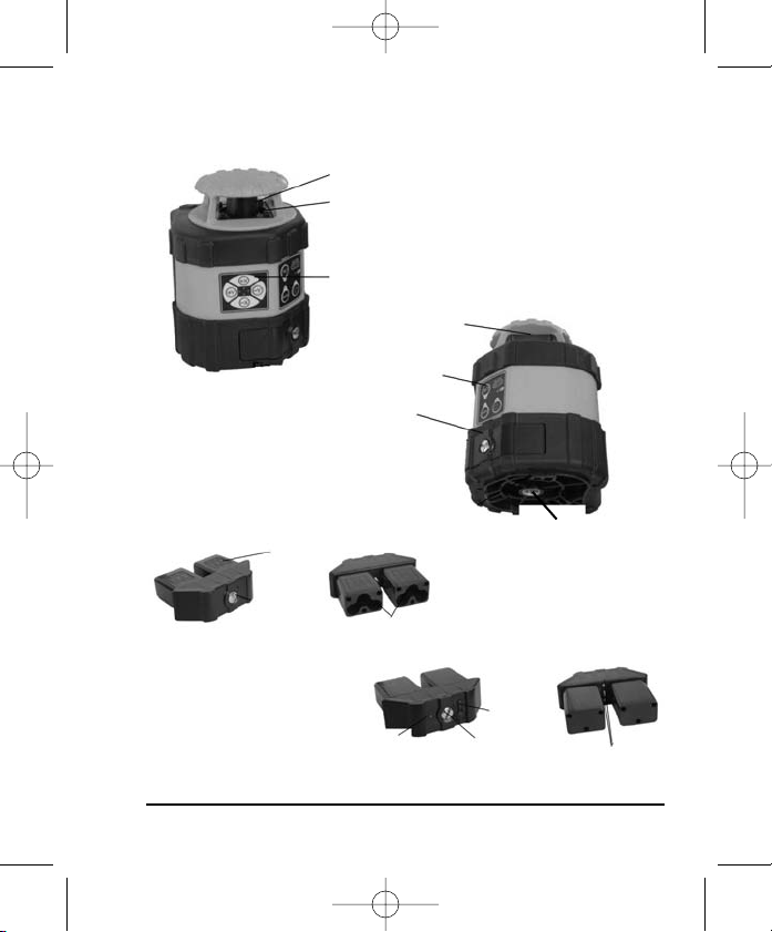
5. Location of Part/Components
Rotary head
Remote control receiver
Keypad
Laser Output
Window
Keypad
Battery-case
locking screw
Polarity indication
of battery
Battery compartment
Charging LED
©2008 Johnson Level & Tool 5
5/8” - 11 screw thread
Adapter
plug
Locking screw
Contact
Points
Page 6
1467H-English 8/6/08 10:07 AM Page 6
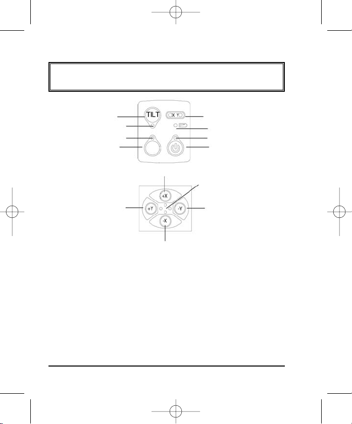
6. Operating Instructions
IMPORTANT: It is the responsibility of the user to verify the
calibration of the instrument before each use.
Tilt button
Tilt LED
Vibrate-mode LED
Vibrate button
VIB
Slope-direction LED
Low battery LED
Power LED
Power button
Fig. 5
+X Beam Shield axis beam
Shield LED
+Y Axis
-Y Axis
Fig. 6
-X Axis
Power LED:
LED light on = power-on; LED light off = power-off
Low Battery LED:
LED light on = low battery voltage; LED light off = normal battery voltage
Vibrate-mode LED:
LED light on = vibrate-mode on; LED light off = vibrate-mode off
Slope LED on X/Y Axis:
LED light on = slope-mode in X or Y axis (need to actuate w/remote control)
Flashing LED means self-calibration on X/Y direction mode on (see
Self-Calibration section)
6 ©2008 Johnson Level & Tool
Page 7

1467H-English 8/6/08 10:07 AM Page 7
Tilt LED:
LED light on = Tilt mode on; LED light off = Tilt mode off;
Flashing LED light = Tilt in warning mode
Beam Shield LED:
LED light on = shielding the laser beam in this axis
Power on/off:
Press button, the lasers power is on, and the power LED
light goes on.
When the power is turned on, the laser is in the
electronic self-leveling mode with an 800rpm rotate speed and
there is no beam shield area for approximately 90 seconds. The
laser will automatically enter into the “TILT” mode and the LED
light goes on.
Tilt mode:
Press button, the LED light will go on and the unit will be in
TILT mode. If the unit is moved or bumped while in operation,
the
the laser will stop rotating and the laser beam and TILT LED will
both flash. Pressing the TILT button again will turn the TILT mode
off and the laser will electronically self-level itself and begin rotation.
Note: The TILT function does not operate in the slope mode.
Vibrate mode:
VIB
Press button, the LED will light, which means laser is in
te mode. Vibrate mode allows continuous operation during
vibra
VIB
high winds, vibrations and shocks. Slight movements are ignored
and the laser self-levels only if significant movement occurs.
Press button again, to turn vibrate off.
VIB
©2008 Johnson Level & Tool 7
Page 8

1467H-English 8/6/08 10:07 AM Page 8
Beam shield mode:
Press the Beam Shield button of the axis you wish to shield the beam
from. The corresponding LED light will turn on and this direction
is shielded. From one to three quadrants can be shielded
simultaneously.
Remote control mode:
This laser can be operated with the remote control included. The
keypad of the remote control is sho
wn in figure 7. The functions
of SLOPE, TILT, SHIELD, SLEEP, and SELF-CALIBRATION can all be
operated by remote control.
SLOPE up/down button
SLOPE button
Tilt button
Direction button of
self-calibration
-Y
+Y
-X
Shield button
Sleep button
Confirm button of
self-calibration
Adjust button of
self-calibration
+X
Slope mode:
The slope function can only be operated using the remote control.
The keypad of remote control is sho
wn as follows.
Fig. 7
+X
SLOPE up/down button
SLOPE axis button
-Y
+Y
-X
Sleep mode button
Fig. 8
8 ©2008 Johnson Level & Tool
Page 9

1467H-English 8/6/08 10:07 AM Page 9
Press the SLOPE button to enter the SLOPE function. The SLOPE on
X-axis is set as the default. SLOPE LED light on in X-axis.
Press button to adjust the slope angle on X-axis. Press the
SLOPE button again to change the SLOPE to the Y-axis. SLOPE
LED light on in Y-axis. Press key to adjust the
slope angle on Y-axis. If the SLOPE angle is beyond its range, the
laser will stop rotating and alarm horn will sound. When it is in
SLOPE mode, the laser will exit TILT mode automatically.
Sleep mode:
Press the sleep button on the remote control to turn on/off the
sleep mode.
The laser will not self-level and the laser beam will
shut off. The power LED light will stay on and all other LED lights
will turn off. All the buttons on the laser key pad will not operate
except the power button. All the buttons on remote control will
not operate except the sleep button. The laser will turn off after
30 min sleep. When turning off the sleep mode, the laser will
return to the mode it was previously in.
Alarming mode when beyond self-leveling range:
When the laser is tilted beyond its self-leveling range, it will stop
ting and laser beam will blink and the alarm will sound.
rota
©2008 Johnson Level & Tool 9
Page 10

1467H-English 8/6/08 10:07 AM Page 10
7. Using the Product
Alkaline Battery Installation
Loosen the locking screw, put 6 “AA” alkaline batteries into the
battery case according to the polarity indication shown on the
battery case. Then put the battery case into the instrument and
tighten the locking screw.
Rechargeable Battery Case
Put rechargeable battery case into laser then tighten locking screw.
Adapter
Connect the laser to the adapter
through the outlet socket on the
ttery cover. The LED displays red
ba
during charging and turns green
when finished charging.
10 ©2008 Johnson Level & Tool
Page 11

1467H-English 8/6/08 10:07 AM Page 11
8. Self-Check and Calibration
IMPORTANT: It is the responsibility of the user to verify the
calibration of the instrument before each use.
Accuracy Check
50’
1. Put the laser on a tripod 50’ away from the wall. Put the laser
on the tripod with X+ axis towards wall.
2. Power on and after self-leveling,
mark “A” on the wall where the detector indicates on grade with
the laser beam.
3. Turning the instrument 90º,Y+, X-, Y-, after the laser self-levels,
mark “B” for Y+, “C” for X- and “D” for Y- on the front wall. Make
sure points B, C, D are in the same vertical line as point A.
4. Measure the vertical distance between the highest and lowest
points between A, B, C, D and mark that “h”.
5. If “h” is less than 1/32”, the accuracy is good. If it is more than
1/32”, the accuracy is beyond its tolerance and the laser needs to
be recalibrated.
using the detector, make a
©2008 Johnson Level & Tool 11
Page 12

1467H-English 8/6/08 10:07 AM Page 12
Re-calibration
Referencing the results of the self-check and using the “h” mark (the
mid-point between the highest and the lowest point among A, B, C, D).
1. Enter self-calibration mode
a. Power off the instrument and face the X-axis towards the wall.
b. Press button and button simultaneously. Then
VIB
release the power button while still pressing the vibrate button.
Release the vibrate button after all LED flashes three times. The
laser will enter self-calibration mode and continuously rotates.
2. X-axis calibration
a. Opening the cover on the remote control, press the
button, the X LED light on the laser keypad flashes
which means the laser has entered the self-calibration mode
for X-direction.
b. Press button to make the laser beam move up and
down until it coincides with the “h” mark.
3. Y-axis calibration
a. Turn the instrument by 90º in self-calibration mode and
make Y-axis facing the wall.
b. Press button, the Y LED light on the laser keypad
flashes which means the laser enters self-calibration mode for
Y-direction.
c. Press button to make the laser beam move up and
down until it coincides with the “h” mark.
4. Self-calibration confirmation
Press key after finishing re-calibration on both X and Y
12 ©2008 Johnson Level & Tool
Page 13

1467H-English 8/6/08 10:07 AM Page 13
axis. The re-calibration LED turns off and the value of the
re-calibration will be stored. The laser has now exited
re-calibration mode.
Note: In order to make the saved calibration effective, you must
wer off the instrument after calibration, and then power it
po
on again. Y-axis accuracy check is a necessity after the X-axis
calibration, and X-axis accuracy check is also a necessity after
the Y-axis calibration. Laser re-calibration will not be finished
until both X-axis and Y-axis accuracy meet the specifications.
Detector Usage
1. Product Description
A laser detector is an indispensable accessory when using this rotar
laser level. The main function of the detector is to locate the position
of laser signals transmitted by rotary lasers. This detection quickly
and precisely provides the user with the horizontal reference. This
product features a high level of sensitivity, a double-faced display, low
power consumption, reliability and easy use.
2. Technical Specifications
Detecting accuracy Fine ±0.039" (±1mm)
Turn-off time 6 minutes ±1 minute
Power 1 9V battery
Sound indicator slow short sounds, rapid short sounds
LED indicator up, level, down
Dimensions 5.906" x 2.992" x 1.142" (150 x 76 x 29mm)
Weight 0.485 lb. (220g)
Others Rain and dust resistant
©2008 Johnson Level & Tool 13
Coarse ±0.098" (+2.5mm) when range is < 492 ft. (150m)
±0.138" (+3.5mm) when range is > 492 ft. (150m)
and a continuous sound
y
Page 14

1467H-English 8/6/08 10:07 AM Page 14
9. Technical Specifications
Laser Wavelength 635nm±10nm
Laser Classification Class IIIa
Maximum Power Output ≤5mW
y ±1/16"/100 ft. (±1.5mm/30m)
Accurac
Exterior Range Up to 2000 ft. (600m) diameter
Remote Range Up to 100 ft. (30m) diameter with remote
Auto-Leveling Range ±5°
Slope ±5º
Power Supply Rechargeable battery pack, or 6V adapter
(included) or 6 “AA” battery holder
(batteries not included).
Battery Life
Dimensions 5.512" x 5.512" x 7.480"
Weight 3.968 lbs. (1.8Kg)
Working Temperature 14°F to 113°F (-10°C to 45°C)
Center Screw Thread 5/8" – 11
Rotation Speed 800 rpm
IP Protection Class 66
Approx. 17 hours with rechargeable battery
pack, 8 hours with 3 “AA” alkaline batteries
and 17 hours with 6 “AA” batteries
(140 x 140 x 190mm)
14 ©2008 Johnson Level & Tool
Page 15

1467H-English 8/6/08 10:07 AM Page 15
10. Application Demonstrations
Squaring Leveling
Elevation
©2008 Johnson Level & Tool 15
Grading
Set Forms
Page 16

1467H-English 8/6/08 10:07 AM Page 16
11. Care and Handling
• This laser unit is a precision tool that must be handled with care.
• Avoid exposing unit to shock vibrations and extreme temperatures.
• Before moving or transporting the unit, make sure that the unit is
turned off.
• Remove the batteries when storing the unit for an extended time
(more than three months) to avoid damage to the unit should the
batteries deteriorate.
• Always store the unit in its case when not in use.
• Avoid getting the unit wet.
• Keep the laser unit dry and clean, especially the laser output window.
Remove any moisture or dirt with a soft, dry cloth.
• Do not use harsh chemicals, strong detergents or cleaning solvents
to clean the laser unit.
16 ©2008 Johnson Level & Tool
Page 17

1467H-English 8/6/08 10:07 AM Page 17
12. Product Warranty
Johnson Level & Tool offers a one year limited warranty on each its
products. You can obtain a copy of the limited warranty for a
Johnson Level & Tool product by contacting Johnson Level & Tool's
Customer Service Department as provided below or by visiting us
online at www.johnsonlevel.com. The limited warranty for each
product contains various limitations and exclusions.
Do not return this product to the store/retailer or place of purchase.
Required repair/calibration must be done by an authorized AccuLine
®
service center or Johnson Level & Tool's limited warranty, if
Pro
applicable, will be void and there will be NO WARRANTY. Contact our
Customer Service Department to obtain a Return Material
Authorization (RMA) number for return to an authorized service center.
Proof of purchase is required.
NOTE: The user is responsible for the proper use and care of the
product.
It is the responsibility of the user to verify the calibra
instrument before each use.
For further assistance, or if you experience problems with this product
that are not addressed in this instruction manual, please contact our
Customer Service Department.
In the U.S., contact Johnson Level & Tool’s Customer Service
Department at 800-563-8553.
In Canada, contact Johnson Level & Tool’s Customer Service
Department at 800-346-6682.
tion of the
©2008 Johnson Level & Tool 17
Page 18

1467H-English 8/6/08 10:07 AM Page 18
13. Product Registration
Enclosed with this instruction manual you will find a warranty card to be
completed for product warranty registration. Product warranty registration
can also be completed online at our web site www.johnsonlevel.com.
You will need to locate the serial number for your product that is located
on the bottom of the unit. PLEASE NOTE THAT IN ADDITION TO ANY
THER LIMITATIONS OR CONDITIONS OF JOHNSON LEVEL &
O
TOOL'S LIMITED WARRANTY, JOHNSON LEVEL & TOOL MUST
HAVE RECEIVED YOUR PROPERLY COMPLETED WARRANTY CARD
WITHIN 30 DAYS OF YOUR PURCHASE OF THE PRODUCT OR ANY
LIMITED WARRANTY THAT MAY APPLY SHALL NOT APPLY AND
THERE SHALL BE NO WARRANTY.
14. Accessories
AccuLine Pro®accessories are available for purchase through
authorized AccuLine Pro dealers. Use of non-AccuLine Pro accessories
will void any applicable limited warranty and there will be NO WARRANTY.
If you need any assistance in locating any accessories, please contact
our Customer Service Department.
In the U.S., contact Johnson Level & Tool’s Customer Service
Department at 800-563-8553.
In Canada, contact Johnson Level & Tool’s Customer Service
Department at 800-346-6682.
18 ©2008 Johnson Level & Tool
 Loading...