

Page 1
6697H-English_Manuals 1/31/13 10:54 AM Page 1
Manual-Leveling Rotary Laser
Model Nos. 40-6502 and 40-6512
Instruction Manual
Congratulations on your choice of this Manual-Leveling Rotary Laser.
We suggest you read this instruction manual thoroughly before using
the instrument. Save this instruction manual for future use.
This is a Class IIIa laser tool and is manufactured to comply
with CFR 21, parts 1040.10 and 1040.11 as well as international
safety rule IEC 285.
©2013 Johnson Level & Tool - Rev. 2 1
Page 2
6697H-English_Manuals 1/31/13 10:54 AM Page 2
Table of Contents
1. Kit Contents
2. Features and Functions
3. Safety Instructions
4. Location/Content
of Warning Labels
5. Location of Parts/Components
6. Operating Instructions
7. Using the Product
8. Self-Check & Fine Calibration
9. Technical Specifications
10. Application Demonstrations
11. Care and Handling
12. Product Warranty
13. Warranty Registration
14. Accessories
1. Kit Contents
For Model No. 40-6502
Description
Manual-Leveling Rotary Laser 1
“AA” Alkaline Batteries 4
Tinted Glasses 1
Instruction Manual with Warranty Card 1
Soft-sided Carrying Case 1
Qty.
For Model No. 40-6512
Description
Manual-Leveling Rotary Laser 1
“AA” Alkaline Batteries 4
Wall/Ceiling Mount 1
8’ Grade Rod 1
Detector with 2 “AAA” Batteries and Clamp 1
Tinted Glasses 1
Magnetic Target 1
Elevating Tripod 1
Instruction Manual with Warranty Card 1
Hard-Shell Carrying Case 1
2 ©2013 Johnson Level & Tool - Rev. 2
Qty.
Page 3
6697H-English_Manuals 1/31/13 10:54 AM Page 3
2. Features and Functions
• Emits a horizontal laser plane.
• Emits a vertical laser plane with simultaneous 90º split beam.
• Large and small scan modes achieve a chalk line.
• Scan line can be moved clockwise or counter-clockwise.
• Variable rotation speed.
• Rugged Housing.
3. Safety Instructions
Please read and understand all of the following instructions, prior
to using this tool. Failure to do so, may void the warranty.
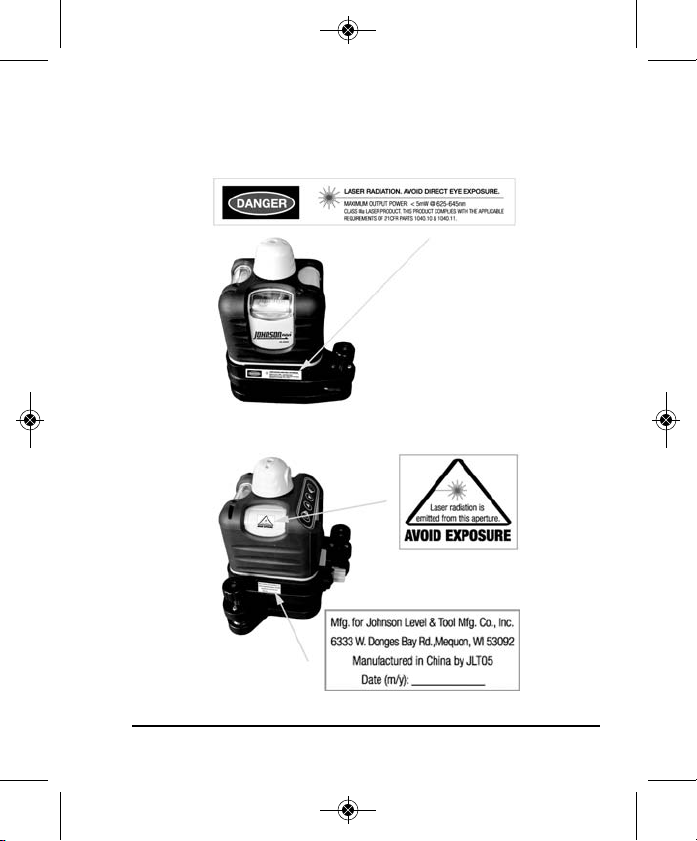
DANGER!
Class IIIa Laser Product
Max. Power Output: ≤ 5mW
Wavelength: 625-645nm
THIS TOOL EMITS LASER RADIATION.
DO NOT STARE INTO BEAM.
AVOID DIRECT EYE EXPOSURE.
©2013 Johnson Level & Tool - Rev. 2 3
Page 4
6697H-English_Manuals 1/31/13 10:54 AM Page 4
ATTENTION IMPORTANT
• Read all instructions prior to operating this laser tool. Do not remove any labels from tool.
• Do not stare directly at the laser beam.
• Do not project the laser beam directly into the eyes of others.
• Do not set up laser tool at eye level or operate the tool near a reflective surface as
the laser beam could be projected into your eyes or into the eyes of others.
• Do not place the laser tool in a manner that may cause someone to unintentionally
look into the laser beam. Serious eye injury may result.
• Do not operate the tool in explosive environments, i.e. in the presence of gases or
flammable liquids.
• Keep the laser tool out of the reach of children and other untrained persons.
• Do not attempt to view the laser beam through optical tools such as telescopes as
serious eye injury may result.
• Always turn the laser tool off when not in use or left unattended for a period of time.
• Remove the batteries when storing the tool for an extended time (more than 3 months)
to avoid damage to the tool should the batteries deteriorate.
• Do not attempt to repair or disassemble the laser tool. If unqualified persons attempt
to repair this tool, warranty will be void.
®
• Use only original Johnson
authorized dealer. Use of non-Johnson®parts and accessories will void warranty.
parts and accessories purchased from your Johnson
®
4 ©2013 Johnson Level & Tool - Rev. 2
Page 5
6697H-English_Manuals 1/31/13 10:54 AM Page 5
4. Location/Content of Warning Labels
©2013 Johnson Level & Tool - Rev. 2 5
Page 6
6697H-English_Manuals 1/31/13 10:54 AM Page 6
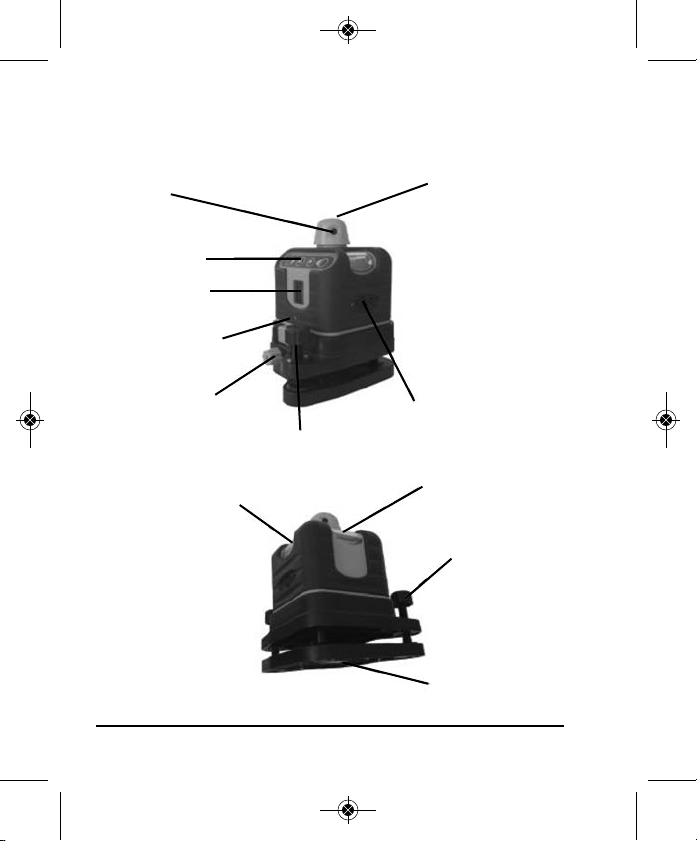
5. Location of Part/Components
Rotating beam
output window
Keypad
Z-level Vial
Z-vial calibrating
hole
Base unlock/lock
knob
90º Split Beam
Output Window
DC 6V outlet
Y-vial leveling knob
X-level Vial
Y-level Vial
X-vial leveling
knob
5/8” - 11 thread
6 ©2013 Johnson Level & Tool - Rev. 2
Page 7
6697H-English_Manuals 1/31/13 10:54 AM Page 7
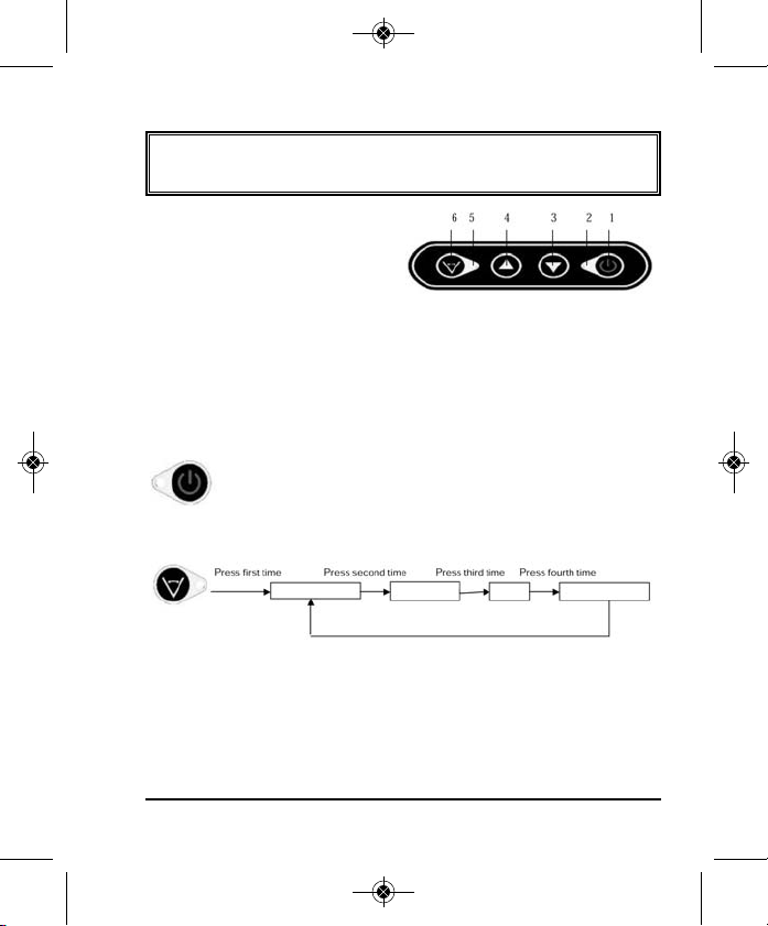
6. Operating Instructions
IMPORTANT: It is the responsibility of the user to verify the
calibration of the instrument before each use.
1. Power ON/OFF
2. Power LED
3. Decrease rotation
speed/rotate scan clockwise
4. Increase rotation speed/rotate scan counterclockwise
5. Scan and rotate mode LED
6. Scan mode key
1. Power ON/OFF: Press this key to turn on or turn off the laser.
ON rotary laser is on, power LED (2) is on (when
battery is low the power LED will blink)
OFF laser and power LED (2) is off
2. Scan mode key: Press this key to change the scan size
Small scan
Big scan DOT
Fast rotation
Fast Rotation: When the laser is turned on, the laser is in its fastest
rotation speed (scan & rotate mode LED (5) is on), laser is rotating.
Small scan: Laser is in small scan (scan & rotate mode LED (5) blinks).
Big scan: Laser is in big scan (scan & rotate mode LED (5) blinks).
©2013 Johnson Level & Tool - Rev. 2 7
Page 8

6697H-English_Manuals 1/31/13 10:54 AM Page 8
DOT: Laser stops rotating and projects a DOT (scan & rotate mode
LED (5) blinks).
3. UP and Down Keys:
In the rotation mode:
Press rotation speed increases (Note: when turning the power on,
the laser is in its highest rotation speed)
Press rotation speed decreases
In the scan mode:
Press scan moves in counterclockwise direction
Press scan moves in clockwise direction
8 ©2013 Johnson Level & Tool - Rev. 2
Page 9

6697H-English_Manuals 1/31/13 10:54 AM Page 9
7. Using the Product
Connecting the Laser to its Base
Horizontal
Vertical
Position the two slots on the laser into the base, tighten the locking
knob to secure the base to the laser. The laser can now be
secured to a tripod.
Battery Installation
1. Disconnect the laser from the base as shown in the figure on the
next page (rotate the base unlock/lock knob counterclockwise to
unlock the laser from the base).
2. Remove battery cover (rotate the battery compartment knob counterclockwise to the open position).
3. Put in 4 “AA” alkaline batteries following the polarity specified in
the battery compartment.
Base
Unlock/Lock
Knob
©2013 Johnson Level & Tool - Rev. 2 9
Page 10

6697H-English_Manuals 1/31/13 10:54 AM Page 10
4. Put the battery cover back into place (rotate the battery compartment knob to the lock position).
Battery
compartment
Base
Unlock/Lock
Knob
Level Vial Adjustment: To adjust the laser to center the vial.
X-vial leveling
knob
Y-vial
leveling knob
X-level Vial
Y-level Vial
Z-level Vial
Z-vial
leveling
knob
Horizontal status
Vertical status
Horizontal Usage
1. Put 4 “AA” alkaline batteries in the unit.
2. As shown above, place the laser on a flat surface or
5/8” - 11 tripod
3. Adjust the vial leveling knobs to center the bubble inside the
X-vial and Y-vial.
4. Turn on the laser.
5. After finishing work, turn off the laser.
10 ©2013 Johnson Level & Tool - Rev. 2
Page 11

6697H-English_Manuals 1/31/13 10:54 AM Page 11
Vertical Usage
1. Put 4 “AA” alkaline batteries in the unit.
2. As shown in figure on previous page, place the laser on a flat
surface or 5/8” - 11 tripod
3. Adjust the vial leveling knobs to center the bubble inside the
Z-vial.
4. Turn on the laser.
5. After finishing work, turn off the laser.
Detector Usage (included in Model No. 40-6512)
1. Technical Specifications
Detecting accuracy ±1.5mm (<50m) ±2.5mm (>50m)
Turn-off timer 6 min ±1min
Power 2 “AAA” Batteries
Battery life 45 hours of continuous use
Sound function Short sound and solid sound
LED indication Upper red, middle orange, middle green,
down red
Size 4.645” x 2.637” x 0.984”
(118mm x 67mm x 25mm)
Weight 0.253 lbs. (115g)
©2013 Johnson Level & Tool - Rev. 2 11
Page 12

6697H-English_Manuals 1/31/13 10:54 AM Page 12
2. Components
(a) Structure
1. Holding Cord
2. Signal Indicator
3. Horn
4. Horizontal Vial
5. Detecting Window
6. Reference Front Marker
7. Power Key
8. Back Reference Marker
9. Connection Port
10. Battery Door
(b) Display
When first turning the detector on, the middle signal
indicator turns red first and then turns green. If the horn
gives two short sounds and the unit powers off
automatically, it means that the battery voltage is
seriously low and it is necessary to replace the battery
immediately. When turning the power on and the down
signal indicator flashes, it means that the battery is low
and it is necessary to replace the battery.
Power Key: Turn on/off the instrument
3. Battery Installation
1. Open the battery cover and put the batteries into the battery
case according to the polarity shown in the battery slot.
2. Snap the battery cover back.
12 ©2013 Johnson Level & Tool - Rev. 2
Page 13

6697H-English_Manuals 1/31/13 10:54 AM Page 13
Note: Take the batteries out when the unit is not in use for a
long time.
4. Detecting Methods
1. This unit can detect a red rotating laser beam.
2. Press the Power Key once , the middle signal indicator will
quickly turn red first and then turns green. It will beep once
to indicate that the instrument is ON.
While detecting, the signal indicators show as follows:
The lower red
LED is on
Laser Line
The upper red
LED is on
Laser Line
The middle LED
is orange
Laser Line
The middle LED
is green
Laser Line
All LEDs
are off
The laser beam isupThe laser beam is
Sound: Single short
sound
down
Sound: Single short
sound
The laser beam is close
to center
Sound: Single short
sound
The laser beam is
exactly to center
Sound: Solid sound Sound:
No laser
beam is
detected
No Sound
Note:
1. While detecting a horizontal laser beam, it is necessary to
have the horizontal bubble vial centered, as the tilt of the
detector will influence its receiving accuracy.
©2013 Johnson Level & Tool - Rev. 2 13
Page 14

6697H-English_Manuals 1/31/13 10:54 AM Page 14
Horizontal Vial
2. Keep the detecting window facing the
rotating laser.
3. Keep the detector still while detecting the
laser beam
4. When the laser beam is centered, mark at
the front reference marker.
5. When the detector does not
receive a laser signal for 6
minutes, and there are no buttons
pushed during these 6 minutes,
the middle signal indicator will turn
green first and then turn red. The
horn will give two short sounds and the unit will power off
automatically.
5. Accessories Usage
• Connecting to the grade rod bracket
14 ©2013 Johnson Level & Tool - Rev. 2
Page 15

6697H-English_Manuals 1/31/13 10:54 AM Page 15
• Connecting to the grade rod
The top of the bracket should be level
with the back reference marker line
6. Maintenance
• When you are done using the detector, return it to its case.
• Keep the detector, particularly the detecting window, clean. If unit
becomes dusty, use a clean cloth to gently wipe it clean.
• Avoid knocking the unit over or allowing it to fall on the ground.
• Although the detector is rain resistant, you should avoid
submerging the unit in water or other liquids. If unit comes into
contact with water or other liquids, wipe it dry immediately.
• Do not use unit around fire or expose it to fire in any way.
©2013 Johnson Level & Tool - Rev. 2 15
Page 16

6697H-English_Manuals 1/31/13 10:54 AM Page 16
8. Self-Check & Fine Calibration
IMPORTANT: It is the responsibility of the user to verify the
calibration of the instrument before each use.
Checking for Accuracy:
Wall
Platform
1. Start by placing the laser 1’ away from a wall (near wall), and
at least 20’ from a wall (far wall).
2. Align the laser so that one axis (vial) points to both walls.
3. Turn the laser on and adjust the thumbscrews until the unit is
level in both the X and Y axis.
4. Make a mark where the laser hits the near wall (wall #1), and
then the same for the far wall (wall #2).
5. Next, move the laser to 1’ next to the far wall, and ensure it is
in the same axis.
6. Level the laser, and then adjust the height so that the laser is
level and hits the mark you made on the far wall (wall #2).
You may need to re-level to achieve this.
Vertical Line
Horizontal Reference Line
16 ©2013 Johnson Level & Tool - Rev. 2
Page 17

6697H-English_Manuals 1/31/13 10:54 AM Page 17
7. Then walk over to the original near wall (wall #1) and measure
the difference between the original mark and the laser line. If
the value is more than 1/4” at 100’, then calibration is required.
8. Ensure accuracy is verified for both the X and Y axis.
Note: X and Y axis are determined by the end user, either vial can be
considered X/Y.
Adjusting Accuracy:
1. Measure the difference between the original near wall mark
(wall #1) and where the laser is hitting the near wall.
2. Walk back to the far wall (wall #2) and adjust the laser so that
it is halfway between the two near wall marks (pencil mark
and laser mark).
3. Next, remove the screw cap for the vial for the axis you are
working with, and using a 2.5mm hex tool, adjust the vial so
that it appears level.
Inner Hexagon Spanner
Y-Direction Level
X-Direction Level
Calibration Hole
X-Direction Level
Y-Direction Level
Calibration Hole
©2013 Johnson Level & Tool - Rev. 2 17
Page 18

6697H-English_Manuals 1/31/13 10:54 AM Page 18
9. Technical Specifications
Laser Wavelength 635nm±10nm
Laser Classification Class IIIa
Maximum Power Output ≤5mW
Accuracy ±1/4"/100 ft. (±2mm/10m)
Interior Range Up to 200 ft. (60m) diameter depending
upon light conditions
Exterior Range Up to 800 ft. (240m) diameter with detector
Power Supply 4 “AA” alkaline batteries
Battery Life
Dimensions 5.118" x 5.118" x 6.141"
Weight 1.653 lbs. (0.75Kg)
Working Temperature 14°F to 113°F (-10°C to +45°C)
Center Screw Thread 5/8" – 11
Rotation speeds 150-300 rpm
Scanning mode Large, Small, Dot
IP Protection Class 54
Approx. battery life 15 hours continuous use
(130 x 130 x 156mm)
18 ©2013 Johnson Level & Tool - Rev. 2
Page 19

6697H-English_Manuals 1/31/13 10:54 AM Page 19
10. Application Demonstrations
Ceiling installation
Window installation
Hanging pictures
©2013 Johnson Level & Tool - Rev. 2 19
Anti-static flooring installation
Baseboard installation
Dormer installation
Page 20

6697H-English_Manuals 1/31/13 10:54 AM Page 20
11. Care and Handling
• This laser unit is a precision tool that must be handled with care.
• Avoid exposing unit to shock vibrations and extreme temperatures.
• Before moving or transporting the unit, make sure that the unit is turned off.
• Remove the batteries when storing the unit for an extended time (more than
three months) to avoid damage to the unit should the batteries deteriorate.
• Always store the unit in its case when not in use.
• Avoid getting the unit wet.
• Keep the laser unit dry and clean, especially the laser output window.
Remove any moisture or dirt with a soft, dry cloth.
• Do not use harsh chemicals, strong detergents or cleaning solvents to clean
the laser unit.
12. Product Warranty
Johnson Level & Tool offers a three year limited warranty on each of its products.
You can obtain a copy of the limited warranty for a Johnson Level & Tool
product by contacting Johnson Level & Tool's Customer Service Department,
as provided below, or by visiting our web site at www.johnsonlevel.com. The
limited warranty for each product contains various limitations and exclusions.
Do not return this product to the store/retailer or place of purchase.
Non-warranty repairs and course calibration must be done by an authorized
Johnson®service center or Johnson Level & Tool's limited warranty, if
applicable, will be void and there will be NO WARRANTY. Contact one of our
service centers for all non-warranty repairs. A list of service centers can be
found on our web site at www.johnsonlevel.com or by calling our Customer
Service Department. Contact our Customer Service Department for Return
Material Authorization (RMA) for warranty repairs (manufacturing defects
only). Proof of purchase is required.
20 ©2013 Johnson Level & Tool - Rev. 2
Page 21

6697H-English_Manuals 1/31/13 10:54 AM Page 21
NOTE: The user is responsible for the proper use and care of the product. It is the
responsibility of the user to verify the calibration of the instrument before each use.
For further assistance, or if you experience problems with this product that are not
addressed in this instruction manual, please contact our Customer Service Dept.
In the U.S., contact Johnson Level & Tool’s Customer Service Department at
888-9-LEVELS.
In Canada, contact Johnson Level & Tool’s Customer Service Department at
800-346-6682.
13. Warranty Registration
Enclosed with this instruction manual you will find a warranty
registration card to be completed for your product. You will need to
locate the serial number for your product that is located on the bottom
of the unit. PLEASE NOTE THAT IN ADDITION TO ANY OTHER
LIMITATIONS OR CONDITIONS OF JOHNSON LEVEL & TOOL'S
LIMITED WARRANTY, JOHNSON LEVEL & TOOL MUST HAVE
RECEIVED YOUR PROPERLY COMPLETED WARRANTY CARD AND
PROOF OF PURCHASE WITHIN 30 DAYS OF YOUR PURCHASE OF
THE PRODUCT OR ANY LIMITED WARRANTY THAT MAY APPLY
SHALL NOT APPLY AND THERE SHALL BE NO WARRANTY.
©2013 Johnson Level & Tool - Rev. 2 21
Page 22

6697H-English_Manuals 1/31/13 10:54 AM Page 22
14. Accessories
Johnson®accessories are available for purchase through authorized
®
Johnson
applicable limited warranty and there will be NO WARRANTY. If you need
any assistance in locating any accessories, please contact our
Customer Service Department.
In the U.S., contact Johnson Level & Tool’s Customer Service
Department at 888-9-LEVELS.
In Canada, contact Johnson Level & Tool’s Customer Service
Department at 800-346-6682.
dealers. Use of non-Johnson®accessories will void any
22 ©2013 Johnson Level & Tool - Rev. 2
 Loading...