

Page 1
5821H-English_Manuals 5/2/12 8:04 AM Page 1
Magnetic Digital Laser Level
Model No. 40-6080
Instruction Manual
Congratulations on your choice of this Magnetic Digital Laser Level
with Rotating Display. We suggest you read this instruction manual
thoroughly before using the instrument. Save this instruction manual
for future use.
This is a Class IIIa laser tool and is manufactured to comply
with CFR 21, parts 1040.10 and 1040.11 as well as international
safety rule IEC 285.
©2012 Johnson Level & Tool - Rev. 2 1
Page 2
5821H-English_Manuals 5/2/12 8:04 AM Page 2
Table of Contents
1. Kit Contents
2. Features and Functions
3. Safety Instructions
4. Location/Content
of Warning Labels
5. Location of Parts/Components
6. Operating Instructions
7. Using the Product
8. Self-Check and Fine
Calibration
9. Technical Specifications
10. Care and Handling
11. Product Warranty
1. Kit Contents
Description Qty.
“AAA” Alkaline Batteries 3
Soft-Sided Pouch 1
2. Features and Functions
• LCD can rotate 180º
• 5 construction languages - units of measure (degrees, percent,
mm/m, in/ft in decimal, in/ft in fractional)
• Self-calibrated
• 0º and 90º-position of inclination is confirmed by a signal tone
• Numbers invert for working overhead
• Automatic Shut-off
• Magnetic Base
• 1/4” - 20 thread for connection to tripod
2 ©2012 Johnson Level & Tool - Rev. 2
Page 3
5821H-English_Manuals 5/2/12 8:04 AM Page 3
3. Safety Instructions
Please read and understand all of the following instructions, prior
to using this tool. Failure to do so, may void the warranty.
ATTENTION IMPORTANT
• Read all instructions prior to operating this laser tool. Do not remove any labels from tool.
• Do not stare directly at the laser beam.
• Do not project the laser beam directly into the eyes of others.
• Do not set up laser tool at eye level or operate the tool near a reflective surface as
the laser beam could be projected into your eyes or into the eyes of others.
• Do not place the laser tool in a manner that may cause someone to unintentionally
look into the laser beam. Serious eye injury may result.
• Do not operate the tool in explosive environments, i.e. in the presence of gases or
flammable liquids.
• Keep the laser tool out of the reach of children and other untrained persons.
• Do not attempt to view the laser beam through optical tools such as telescopes as
serious eye injury may result.
• Always turn the laser tool off when not in use or left unattended for a period of time.
• Remove the batteries when storing the tool for an extended time (more than 3 months)
to avoid damage to the tool should the batteries deteriorate.
• Do not attempt to repair or disassemble the laser tool. If unqualified persons attempt
to repair this tool, warranty will be void.
• Use only original Johnson
authorized dealer. Use of non-Johnson®parts and accessories will void warranty.
®
parts and accessories purchased from your Johnson
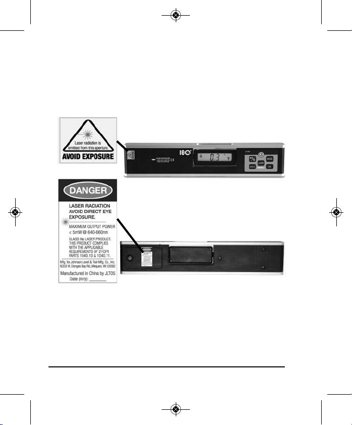
DANGER!
Class IIIa Laser Product
Max. Power Output: ≤ 5mW
Wavelength: 640-660nm
THIS TOOL EMITS LASER RADIATION.
DO NOT STARE INTO BEAM.
AVOID DIRECT EYE EXPOSURE.
®
©2012 Johnson Level & Tool - Rev. 2 3
Page 4
5821H-English_Manuals 5/2/12 8:04 AM Page 4
4. Location/Content of Warning Labels
4 ©2012 Johnson Level & Tool - Rev. 2
Page 5
5821H-English_Manuals 5/2/12 8:04 AM Page 5
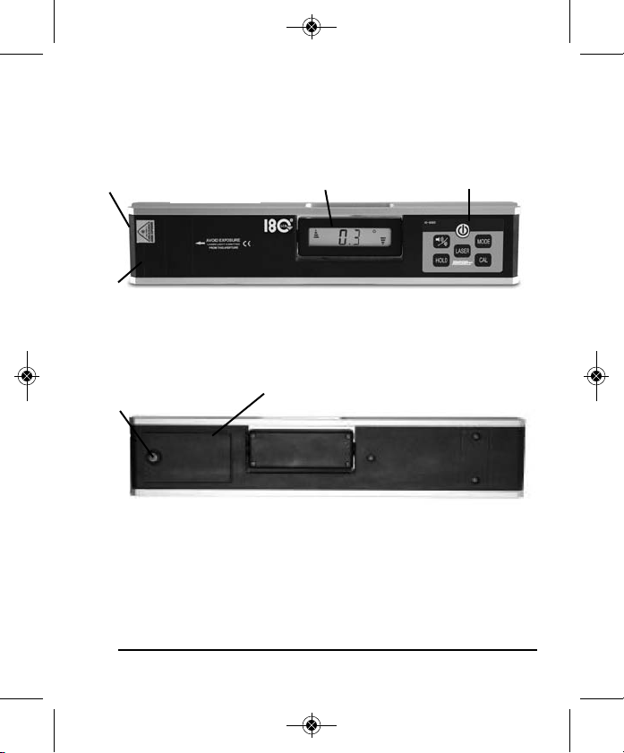
5. Location of Part/Components
LCD DisplayLaser Output Window
1 1/8” Offset
Battery Cover
Battery Cover Screw
©2012 Johnson Level & Tool - Rev. 2 5
Keypad
Page 6

5821H-English_Manuals 5/2/12 8:04 AM Page 6
6. Operating Instructions
IMPORTANT: It is the responsibility of the user to verify the
calibration of the instrument before each use.
Battery Installation
1. Open the battery cover
by turning the screw
counter-clockwise,
and then put the 3 “AAA” batteries into the battery case
according to the polarity shown in the battery slot.
2. Snap the battery cover back, and then tighten the screw clockwise.
Note:
1. Take out the batteries if the instrument is not going to be used
for a long time.
2. Replace the batteries when the voltage gets low.
3. Turn the instrument off while taking out the old batteries from
the battery case.
Display After Installing the Batteries
1. After installing the new batteries the LCD
will display “good”.
2. Then the LCD will display “-0-”.
3. Calibrate the instrument following the
calibration procedure in Section 8.
6 ©2012 Johnson Level & Tool - Rev. 2
Page 7

5821H-English_Manuals 5/2/12 8:04 AM Page 7
7. Using the Product
Key Guide
Sound/LCD
Backlight Key
Hold Key
Power Key
Turn on/off the instrument. The instrument will beep twice
when turned on and beep once when turned off.
Hold Key
Pressing this key will lock the current angle reading
displayed on the LCD.
Sound/LCD Backlight Key
Press this key once and hold for 2 seconds to turn on/off
the LCD back light. The instrument will beep once. Press
button once to turn on/off the sound function. When sound
function is on you will see the horn symbol on the LCD. There will
be no beeps if the instrument is between 10º to 80º. A faster beep
will start as you move closer to level or plumb. A steady tone will
beep when level is at 0.0º or 90º.
Power Key
Mode Key
Calibration Key
Laser Key
©2012 Johnson Level & Tool - Rev. 2 7
Page 8

5821H-English_Manuals 5/2/12 8:04 AM Page 8
Mode Key
Push the MODE button to switch from one construction language
to another. This controls which construction language your
electronic module will measure in. Your level has the capability to
measure in Degrees, Percentage of slope, Millimeters per Meter, Inches
per Foot (Slope, Pitch) in decimal form and Inches per Foot in fractions of
an inch. A symbol on the upper right of the screen will explain which
MODE you are currently in.
Laser Key
Turn on/off the laser. The instrument will beep once.
Calibration Key
Please refer to Section 8 “Self-Check and Fine Calibration”.
Auto Shut-off
The electronic module will automatically shut-off in 20 minutes if no
key is pressed.
Mode
Low Voltage Indication
If the battery symbol on the display is low, change the
batteries as soon as possible. Non-display of battery
symbol means the battery is full.
8 ©2012 Johnson Level & Tool - Rev. 2
Page 9

5821H-English_Manuals 5/2/12 8:04 AM Page 9
Sound Function
The SOUND symbol displayed on the LCD means that the
sound function is activated. The level will beep faster when
the instrument gets closer to the position of 0º and 90º. When the
LCD displays 0º or 90º, there will be a continuous tone sound.
Hold Function
Press the hold key once (unit will beep once) to activate this function
and to display the HOLD symbol on the LCD. Now the instrument will
hold the current angle reading and the display will flash.
Laser Indication Function
The Laser symbol displayed on the LCD means that the laser
beam is activated. The laser output window will emit a bright
red laser dot.
Inclination Indication
The triangle arrows displayed on the two ends of the LCD indicate
the inclination direction of the laser digital level.
©2012 Johnson Level & Tool - Rev. 2 9
Page 10

5821H-English_Manuals 5/2/12 8:04 AM Page 10
When the laser digital level is at the position of 0 degree, the two
arrows will show as follows:
Rotating Display
The LCD of the instrument can rotate 180 degrees.
10 ©2012 Johnson Level & Tool - Rev. 2
Page 11

5821H-English_Manuals 5/2/12 8:04 AM Page 11
8. Self-Check and Fine Calibration
IMPORTANT: It is the responsibility of the user to verify the
calibration of the instrument before each use.
Checking the Horizontal Calibration
Select a flat and horizontal platform as a reference
surface, like a table-surface.
1. Place the laser digital level on this reference
surface, as shown in figure 1, and then record
the measured angle reading. Record this as A1.
2. Turn the laser digital level 180 degrees, as
shown in figure 2, and then record the
measured angle reading. Record this as A2.
3. If A1-A2 is greater than 0.2º, it is necessary to
calibrate the horizontal accuracy.
Checking the Vertical Calibration
Select a flat and vertical platform as a reference
surface.
1. Place the laser digital level on this reference
surface, as shown in figure 3, and then
record the measured angle reading. Record
this as A1.
2. Turn the laser digital level 180 degrees, as
shown in figure 4, and then record the
measured angle reading. Record this as A2.
3. If A1-A2 is greater than 0.2º, it is necessary
to calibrate the vertical accuracy.
©2012 Johnson Level & Tool - Rev. 2 11
Page 12

5821H-English_Manuals 5/2/12 8:04 AM Page 12
Horizontal Calibration
1. Press and hold the ZERO key for 3-plus seconds, unit will beep once.
When the LCD shows -0-, it means the instrument has already
entered the calibration status.
2. Place the laser digital level on the horizontal reference surface, as
shown in figure 5, after 10 seconds, press the ZERO again, and the
LCD shows -1-.
3. Turn the laser digital level 180 degrees, as shown in figure 6, and
after 10 seconds, press the ZERO key again, and the LCD shows -2-.
Wait for 2 seconds, and the laser digital level will show the angle
reading. The horizontal calibration is now completed.
Vertical Calibration
1. Press and hold the ZERO key for 3-plus seconds,
unit will beep once. When the LCD shows -0-, it
means the instrument has already entered the calibration status.
2. Place the laser digital level on the vertical reference
surface, as shown in figure 7, after 10 seconds,
press the ZERO again, and the LCD shows -1-.
3. Turn the laser digital level 180 degrees, as shown in
figure 8, and after 10 seconds, press the ZERO key
again, and the LCD shows -2-. Wait for 2 seconds, and the laser
digital level will show the angle reading. The vertical calibration is
now completed.
12 ©2012 Johnson Level & Tool - Rev. 2
Page 13

5821H-English_Manuals 5/2/12 8:04 AM Page 13
9. Technical Specifications
Laser Wavelength 650nm ± 10
Laser Classification Class IIIa
Maximum Power Output ≤5mW
Accuracy ± 0.1º for 0º and 90º, and
± 0.2º for 1º to 89º
Laser Accuracy ±1/8”/50 ft. (±0.2mm/m)
Range 0º to 90º
Power Supply 3 “AAA” alkaline batteries
Battery Life Approx. battery life 70 hours
continuous use
Dimensions 12" x 2.36" x 1.25"
(305 x 60 x 32mm)
Weight 1.48 lbs (0.67 Kg)
Working Temperature 14°F to 113°F (-10°C to +45°C)
©2012 Johnson Level & Tool - Rev. 2 13
Page 14

5821H-English_Manuals 5/2/12 8:04 AM Page 14
10. Care and Handling
• This laser unit is a precision tool that must be handled
with care.
• Avoid exposing unit to shock vibrations and extreme
temperatures.
• Before moving or transporting the unit, make sure that the
unit is turned off.
• Remove the batteries when storing the unit for an extended
time (more than three months) to avoid damage to the unit
should the batteries deteriorate.
• Always store the unit in its case when not in use.
• Avoid getting the unit wet.
• Keep the laser unit dry and clean, especially the laser output
window. Remove any moisture or dirt with a soft, dry cloth.
• Do not use harsh chemicals, strong detergents or cleaning
solvents to clean the laser unit.
14 ©2012 Johnson Level & Tool - Rev. 2
Page 15

5821H-English_Manuals 5/2/12 8:04 AM Page 15
11. Product Warranty
Johnson Level & Tool offers a one year limited warranty on each its
products. You can obtain a copy of the limited warranty for a
Johnson Level & Tool product by contacting Johnson Level & Tool's
Customer Service Department as provided below or by visiting us
online at www.johnsonlevel.com. The limited warranty for each
product contains various limitations and exclusions.
NOTE: The user is responsible for the proper use and care of the
product.
It is the responsibility of the user to verify the calibration of the
instrument before each use.
For further assistance, or if you experience problems with this product
that are not addressed in this instruction manual, please contact our
Customer Service Department.
In the U.S., contact Johnson Level & Tool’s Customer Service
Department at 888-9-LEVELS.
In Canada, contact Johnson Level & Tool’s Customer Service
Department at 800-346-6682.
©2012 Johnson Level & Tool - Rev. 2 15
Page 16

5821H-English_Manuals 5/2/12 8:04 AM Page 16
16 ©2012 Johnson Level & Tool - Rev. 2
 Loading...