

Page 1
6022H-English_Manuals 7/20/12 11:15 AM Page 1
Manual-Leveling Rotary Laser
Model No. 40-0922
Instruction Manual
Congratulations on your choice of this Manual-Leveling Rotary Laser.
We suggest you read this instruction manual thoroughly before using the
instrument. Save this instruction manual for future use.
This is a Class IIIa laser tool and is manufactured to comply with CRF 21,
parts 1040.10 and 1040.11 as well as international safety rule IEC 285.
©2012 Johnson Level & Tool 1
Page 2
6022H-English_Manuals 7/20/12 11:15 AM Page 2
Table of Contents
1. Contents
2. Features and Functions
3. Safety Instructions
4. Location/Content
of Warning Labels
5. Location of Parts/Components
6. Operating Instructions
7. Using the Product
8. Self-Check & Fine Calibration
9. Technical Specifications
10. Application Demonstrations
11. Care and Handling
12. Product Warranty
13. Warranty Registration
14. Accessories
1. Contents
Description for Model 40-0922 Qty.
Manual-Leveling Rotary Laser
Instruction Manual with Warranty Card 1
2. Features and Functions
• Manual level in horizontal and vertical planes.
• Simultaneous 90º split beam in vertical mode.
• Illuminated vials for easy reading in all conditions.
• Variable rotation speed from 0-600 rpm.
1
2 ©2012 Johnson Level & Tool
Page 3
6022H-English_Manuals 7/20/12 11:15 AM Page 3
3. Safety Instructions
Please read and understand all of the following instructions, prior
to using this tool. Failure to do so, may void the warranty.
DANGER!
Class IIIa Laser Product
Max. Power Output: ≤ 5mW
Wavelength: 640nm-660nm
THIS TOOL EMITS LASER RADIATION.
DO NOT STARE INTO BEAM.
AVOID DIRECT EYE EXPOSURE.
ATTENTION IMPORTANT
• Read all instructions prior to operating this laser tool. Do not remove any labels from tool.
• Do not stare directly at the laser beam.
• Do not project the laser beam directly into the eyes of others.
• Do not set up laser tool at eye level or operate the tool near a reflective surface as
the laser beam could be projected into your eyes or into the eyes of others.
• Do not place the laser tool in a manner that may cause someone to unintentionally
look into the laser beam. Serious eye injury may result.
• Do not operate the tool in explosive environments, i.e. in the presence of gases or
flammable liquids.
• Keep the laser tool out of the reach of children and other untrained persons.
• Do not attempt to view the laser beam through optical tools such as telescopes as
serious eye injury may result.
• Always turn the laser tool off when not in use or left unattended for a period of time.
• Remove the batteries when storing the tool for an extended time (more than 3 months)
to avoid damage to the tool should the batteries deteriorate.
• Do not attempt to repair or disassemble the laser tool. If unqualified persons attempt
to repair this tool, warranty will be void.
• Use only original Johnson
authorized dealer. Use of non-Johnson®parts and accessories will void warranty.
®
parts and accessories purchased from your Johnson
®
©2012 Johnson Level & Tool 3
Page 4
6022H-English_Manuals 7/20/12 11:15 AM Page 4
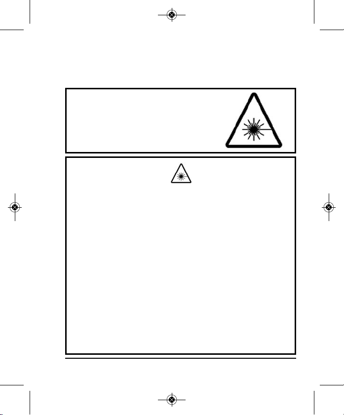
4. Location/Content of Warning Labels
4 ©2012 Johnson Level & Tool
Page 5
6022H-English_Manuals 7/20/12 11:15 AM Page 5
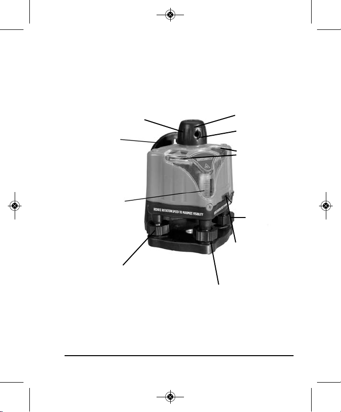
5. Location of Part/Components
Rotary Head
Base with Tripod
Thread and
Wall-Mounting
Bracket
1 - Vertical (plumb)
Vial “Z”
“X” Leveling Screw
90º Split Beam
Output Window
Rotating Beam
Output Window
2 - Horizontal
(level) Vial “X”
and “Y”
“Y” Leveling
Screw
On/Off Switch and
Variable Speed
Control Knob
“Z” Leveling Screw
©2012 Johnson Level & Tool 5
Page 6

6022H-English_Manuals 7/20/12 11:15 AM Page 6
6. Operating Instructions
IMPORTANT: It is the responsibility of the user to verify the
calibration of the instrument before each use.
Battery Installation
Unscrew the cover on the back top of the unit and insert four (4) AA
batteries (not included). Follow polarity on housing.
Note: Used/discharged batteries are hazardous waste and must be
disposed of properly.
Leveling the Laser
Bring the unit into a level position by means of the horizontal “X” and
“Y” adjusting screws (top mounted vials for horizontal application)
and one (1) vertical “Z” adjusting screw (one side mounted vial for
vertical application).
To obtain accurate measures, use the leveling screws found on the
mounting base and ensure that the bubble in each vial is perfectly
centered.
6 ©2012 Johnson Level & Tool
Page 7

6022H-English_Manuals 7/20/12 11:15 AM Page 7
7. Using the Product
To turn on, rotate the on/off and variable speed switch in the
direction indicated by the arrow. Use this on/off and variable speed
control knob to create a single laser point or an intermittent line or
a continuous line. The slower the rotation, the more visible the
beam will be. If used with an optional detector, use fastest rotation
speed.
Note: Due to the 360° rotating feature of the laser beam, extra care
must be taken to avoid direct contact with the eyes.
©2012 Johnson Level & Tool 7
Page 8

6022H-English_Manuals 7/20/12 11:15 AM Page 8
8. Self-Check & Fine Calibration
IMPORTANT: It is the responsibility of the user to verify the
calibration of the instrument before each use.
Checking for Accuracy:
Wall
Platform
1. Start by placing the laser 1’ away from a wall (near wall), and
at least 20’ from a wall (far wall).
2. Align the laser so that one axis (vial) points to both walls.
3. Turn the laser on and adjust the thumbscrews until the unit is
level in both the X and Y axis.
4. Make a mark where the laser hits the near wall (wall #1), and
then the same for the far wall (wall #2).
5. Next, move the laser to 1’ next to the far wall, and ensure it is
in the same axis.
6. Level the laser, and then adjust the height so that the laser is
level and hits the mark you made on the far wall (wall #2).
You my need to re-level to achieve this.
Vertical Line
Horizontal Reference Line
8 ©2012 Johnson Level & Tool
Page 9

6022H-English_Manuals 7/20/12 11:15 AM Page 9
7. Then walk over to the original near wall (wall #1) and measure
the difference between the original mark and the laser line. If
the value is more than 1/8” at 35’, then calibration is required.
8. Ensure accuracy is verified for both the X and Y axis.
Note: X and Y axis are determined by the end user, either vial can be
considered X/Y.
Adjusting Accuracy:
1. Measure the difference between the original near wall mark
(wall #1) and where the laser is hitting the near wall.
2. Walk back to the far wall (wall #2) and adjust the laser so that
it is halfway between the two near wall marks (pencil mark
and laser mark).
3. Next, remove the screw cap for the vial for the axis you are
working with, and using a 2.5mm hex tool, adjust the vial so
that it appears level.
Inner Hexagon Spanner
Y-Direction Level
X-Direction Level
Calibration Hole
X-Direction Level
Y-Direction Level
Calibration Hole
©2012 Johnson Level & Tool 9
Page 10

6022H-English_Manuals 7/20/12 11:15 AM Page 10
9. Technical Specifications
Laser Wavelength 650nm±10nm
Laser Classification Class IIIa
Maximum Power Output ≤5mW
Accuracy ±1/8"/30 ft. (±0.3mm/m)
Interior Range Up to 200 ft. (60m) diameter depending
Power Supply 4 “AA” alkaline batteries (not included)
Battery Life
Dimensions 4.75" x 4.75" x 6.125"
Weight 1.35 lbs (0.6Kg)
Working Temperature 14°F to 113°F (-10°C to +45°C)
Center screw thread 5/8" – 11
Rotation Speed 0-600 rpm
IP Protection Class 43
10 ©2012 Johnson Level & Tool
upon light conditions
Approx. battery life 25 hours continuous use
(120 x 120 x 156mm)
Page 11

6022H-English_Manuals 7/20/12 11:15 AM Page 11
10. Application Demonstrations
Ceiling installation
Window installation
Hanging pictures
©2012 Johnson Level & Tool 11
Anti-static flooring installation
Baseboard installation
Dormer installation
Page 12

6022H-English_Manuals 7/20/12 11:15 AM Page 12
11. Care and Handling
• This laser unit is a precision tool that must be handled with care.
• Avoid exposing unit to shock vibrations and extreme temperatures.
• Before moving or transporting the unit, make sure that the unit is turned off.
• Remove the batteries when storing the unit for an extended time (more than
three months) to avoid damage to the unit should the batteries deteriorate.
• Always store the unit in its case when not in use.
• Avoid getting the unit wet.
• Keep the laser unit dry and clean, especially the laser output window.
Remove any moisture or dirt with a soft, dry cloth.
• Do not use harsh chemicals, strong detergents or cleaning solvents to clean
the laser unit.
12. Product Warranty
Johnson Level & Tool offers a three year limited warranty on each of its products.
You can obtain a copy of the limited warranty for a Johnson Level & Tool
product by contacting Johnson Level & Tool's Customer Service Department,
as provided below, or by visiting our web site at www.johnsonlevel.com. The
limited warranty for each product contains various limitations and exclusions.
Do not return this product to the store/retailer or place of purchase.
Non-warranty repairs and course calibration must be done by an authorized
Johnson®service center or Johnson Level & Tool's limited warranty, if
applicable, will be void and there will be NO WARRANTY. Contact one of our
service centers for all non-warranty repairs. A list of service centers can be
found on our web site at www.johnsonlevel.com or by calling our Customer
Service Department. Contact our Customer Service Department for Return
Material Authorization (RMA) for warranty repairs (manufacturing defects
only). Proof of purchase is required.
12 ©2012 Johnson Level & Tool
Page 13

6022H-English_Manuals 7/20/12 11:15 AM Page 13
NOTE: The user is responsible for the proper use and care of the product. It is the
responsibility of the user to verify the calibration of the instrument before each use.
For further assistance, or if you experience problems with this product that are not
addressed in this instruction manual, please contact our Customer Service Dept.
In the U.S., contact Johnson Level & Tool’s Customer Service Department at
888-9-LEVELS.
In Canada, contact Johnson Level & Tool’s Customer Service Department at
800-346-6682.
13. Warranty Registration
Enclosed with this instruction manual you will find a warranty
registration card to be completed for your product. You will need to
locate the serial number for your product that is located on the bottom
of the unit. PLEASE NOTE THAT IN ADDITION TO ANY OTHER
LIMITATIONS OR CONDITIONS OF JOHNSON LEVEL & TOOL'S
LIMITED WARRANTY, JOHNSON LEVEL & TOOL MUST HAVE
RECEIVED YOUR PROPERLY COMPLETED WARRANTY CARD AND
PROOF OF PURCHASE WITHIN 30 DAYS OF YOUR PURCHASE OF
THE PRODUCT OR ANY LIMITED WARRANTY THAT MAY APPLY
SHALL NOT APPLY AND THERE SHALL BE NO WARRANTY.
©2012 Johnson Level & Tool 13
Page 14

6022H-English_Manuals 7/20/12 11:15 AM Page 14
14. Accessories
Johnson®accessories are available for purchase through authorized
®
Johnson
applicable limited warranty and there will be NO WARRANTY. If you need
any assistance in locating any accessories, please contact our
Customer Service Department.
In the U.S., contact Johnson Level & Tool’s Customer Service
Department at 888-9-LEVELS.
In Canada, contact Johnson Level & Tool’s Customer Service
Department at 800-346-6682.
dealers. Use of non-Johnson®accessories will void any
14 ©2012 Johnson Level & Tool
 Loading...