

Page 1
7295H-English_Manuals 8/28/13 8:42 AM Page 1
Self-Leveling Cross-Line Laser
Model No. 40-0912 & 40-0921
Instruction Manual
Congratulations on your choice of this Self-Leveling Cross-Line Laser.
We suggest you read this instruction manual thoroughly before using
the instrument. Save this instruction manual for future use.
This is a Class IIIa laser tool and is manufactured to comply
with CFR 21, parts 1040.10 and 1040.11 as well as international
safety rule IEC 285.
©2013 Johnson Level & Tool - Rev. 2 1
Page 2
7295H-English_Manuals 8/28/13 8:42 AM Page 2
Table of Contents
1. Kit Contents
2. Features and Functions
3. Safety Instructions
4. Location/Content
of Warning Labels
5. Location of Parts/Components
6. Operating Instructions
7. Using the Product
8. Self-Check & Fine Calibration
9. Technical Specifications
10. Application Demonstrations
11. Care and Handling
12. Product Warranty
13. Warranty Registration
14. Accessories
1. Kit Contents
Model No. 40-0912 Qty.
Self-Leveling Cross-Line Laser
with 360º Rotating Base 1
“AAA” Alkaline Batteries 3
Instruction Manual with Warranty Card 1
Soft-Sided Carrying Case 1
Model No. 40-0921 Qty.
Self-Leveling Cross-Line Laser
with 360º Rotating Base 1
Tinted Glasses 1
Elevating Tripod 1
Instruction Manual with Warranty Card 1
Hard-Shell Carrying Case 1
2. Features and Functions
• Two laser beams to plot both horizontal (level) and vertical
(plumb) lines.
• Self-levels to within a range of ±6°.
• 360º graduated base allows angle layout.
2 ©2013 Johnson Level & Tool - Rev. 2
Page 3
7295H-English_Manuals 8/28/13 8:42 AM Page 3
3. Safety Instructions
Please read and understand all of the following instructions, prior
to using this tool. Failure to do so, may void the warranty.
DANGER!
Class IIIa Laser Product
Max. Power Output: ≤ 5mW
Wavelength: 625-645nm
THIS TOOL EMITS LASER RADIATION.
DO NOT STARE INTO BEAM.
AVOID DIRECT EYE EXPOSURE.
ATTENTION IMPORTANT
• Read all instructions prior to operating this laser tool. Do not remove any labels from tool.
• Do not stare directly at the laser beam.
• Do not project the laser beam directly into the eyes of others.
• Do not set up laser tool at eye level or operate the tool near a reflective surface as
the laser beam could be projected into your eyes or into the eyes of others.
• Do not place the laser tool in a manner that may cause someone to unintentionally
look into the laser beam. Serious eye injury may result.
• Do not operate the tool in explosive environments, i.e. in the presence of gases or
flammable liquids.
• Keep the laser tool out of the reach of children and other untrained persons.
• Do not attempt to view the laser beam through optical tools such as telescopes as
serious eye injury may result.
• Always turn the laser tool off when not in use or left unattended for a period of time.
• Remove the batteries when storing the tool for an extended time (more than 3 months)
to avoid damage to the tool should the batteries deteriorate.
• Do not attempt to repair or disassemble the laser tool. If unqualified persons attempt
to repair this tool, warranty will be void.
• Use only original Johnson
authorized dealer. Use of non-Johnson®parts and accessories will void warranty.
®
parts and accessories purchased from your Johnson
®
©2013 Johnson Level & Tool - Rev. 2 3
Page 4
7295H-English_Manuals 8/28/13 8:42 AM Page 4
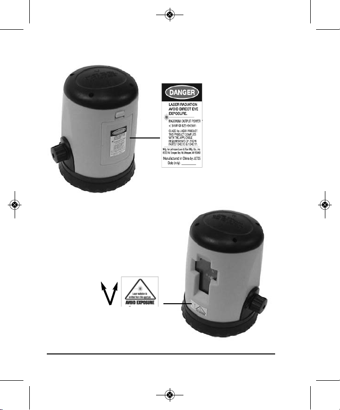
4. Location/Content of Warning Labels
4 ©2010 Johnson Level & Tool - Rev. 1
Page 5
7295H-English_Manuals 8/28/13 8:42 AM Page 5
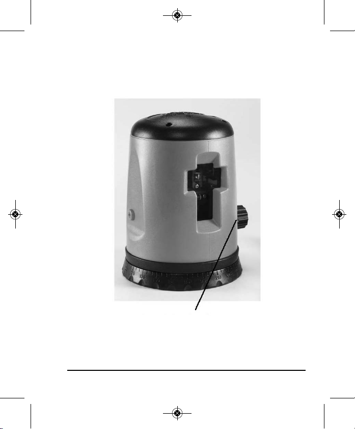
5. Location of Part/Components
Lock/unlock
On/off switch
©2013 Johnson Level & Tool - Rev. 2 5
Page 6

7295H-English_Manuals 8/28/13 8:42 AM Page 6
6. Operating Instructions
IMPORTANT: It is the responsibility of the user to verify the
calibration of the instrument before each use.
Battery Installation
Open the cover on the back of the unit in
accordance with markings on the cover and insert
three AAA batteries (included in 40-0912 only).
Place cover back onto unit.
Note: Used (discharged) batteries are hazardous
waste and should be disposed of properly.
The unit must be locked/turned off before returning the laser to its
case. Locking the unit must be done when the unit is in its upright
position. It is done to hold the internal components in place to avoid
damage to the internal mechanism during transport. The
knob must be unlocked/turned on prior to each use and
locked/turned off after each use of the laser.
Tripod Set-up
Open up the tripod and position it firmly on a surface that is even
and as near level as possible. For uneven surfaces and inclines,
compensate by adjusting the telescoping legs of the tripod. Tightly
screw the unit and tripod together.
Tripod working range from 17" to 47".
The laser can be used either with the tripod or independently.
6 ©2013 Johnson Level & Tool - Rev. 2
Page 7

7295H-English_Manuals 8/28/13 8:42 AM Page 7
7. Using the Product
Horizontal and Vertical Line Projection
Turning on the knob on the side of the unit will generate a simultaneous
vertical and horizontal line laser beam. To turn off, simply turn knob
counter-clockwise. If you have unlocked the knob on side of the unit
(as per previous page) then simply allow for the unit to level itself.
The unit can be manually rotated to the full 360º range.
Note: The laser level is able to compensate for slope of +/- 6º. If
the level is placed on a slope that is too great, it will not be able to
level itself accurately. The laser beam will flash if outside of its
leveling range.
©2013 Johnson Level & Tool - Rev. 2 7
Page 8

7295H-English_Manuals 8/28/13 8:42 AM Page 8
8. Self-Check & Fine Calibration
IMPORTANT: It is the responsibility of the user to verify the
calibration of the instrument before each use.
Re-calibration can be performed as described below:
1. Use a level to mark a horizontal reference line on the wall.
2. Power on the unit to compare the projected horizontal line with
its reference. Compensator has to be locked before making
calibration adjustments. If the line is tilted, remove the side
plastic screw/plug and use a 2 mm hex head wrench to calibrate the unit through its side calibration hole. Rotate the hex
head wrench clockwise when the horizontal line tilts to the
right. Rotate the hex head wrench counter-clockwise when the
horizontal line tilts to the left.
3. If the horizontal line is too low or too high, carefully remove the
housing by removing the four screws located at the top of the
housing. Carefully remove the housing paying close attention
to the power cord inside the unit. Locate the three screws at
the front of the unit below the glass prisms. If the line needs
to be moved down, loosen the two outer screws and tighten
the inner screw. If the line needs to be moved up, loosen the
inner screw and tighten the two outer screws. Reassemble the
housing after completing the calibration procedure.
8 ©2013 Johnson Level & Tool - Rev. 2
Page 9

7295H-English_Manuals 8/28/13 8:42 AM Page 9
9. Technical Specifications
Laser Wavelength 635nm ± 10
Laser Classification Class IIIa
Maximum Power Output ≤5mW
Accuracy ± 1/4"/35 ft. (±0.6mm/m)
Interior Range Up to 100 ft. (30m)
depending upon light conditions
Self-Leveling Range ±6º
Power Supply 3 “AAA” alkaline batteries
(included in 40-0912 only)
Battery Life Approx. battery life 12 hours
continuous use
Dimensions 5" x 4" x 3 1/2"
(127 x 101 x 89mm)
Weight 1.2 lbs. (0.54 Kg)
Working Temperature 14°F to 113°F (-10°C to +45°C)
Center Screw Thread 5/8" – 11
IP Protection Class 54
©2013 Johnson Level & Tool - Rev. 2 9
Page 10

7295H-English_Manuals 8/28/13 8:42 AM Page 10
10. Application Demonstrations
10 ©2013 Johnson Level & Tool - Rev. 2
Page 11

7295H-English_Manuals 8/28/13 8:42 AM Page 11
11. Care and Handling
• This laser unit is a precision tool that must be handled with care.
• Avoid exposing unit to shock vibrations and extreme temperatures.
• Before moving or transporting the unit, make sure that the unit is turned off.
• Remove the batteries when storing the unit for an extended time (more than
three months) to avoid damage to the unit should the batteries deteriorate.
• Always store the unit in its case when not in use.
• Avoid getting the unit wet.
• Keep the laser unit dry and clean, especially the laser output window.
Remove any moisture or dirt with a soft, dry cloth.
• Do not use harsh chemicals, strong detergents or cleaning solvents to clean
the laser unit.
12. Product Warranty
Johnson Level & Tool offers a three year limited warranty on each of its products.
You can obtain a copy of the limited warranty for a Johnson Level & Tool
product by contacting Johnson Level & Tool's Customer Service Department,
as provided below, or by visiting our web site at www.johnsonlevel.com. The
limited warranty for each product contains various limitations and exclusions.
Do not return this product to the store/retailer or place of purchase.
Non-warranty repairs and course calibration must be done by an authorized
Johnson®service center or Johnson Level & Tool's limited warranty, if
applicable, will be void and there will be NO WARRANTY. Contact one of our
service centers for all non-warranty repairs. A list of service centers can be
found on our web site at www.johnsonlevel.com or by calling our Customer
Service Department. Contact our Customer Service Department for Return
Material Authorization (RMA) for warranty repairs (manufacturing defects
only). Proof of purchase is required.
©2013 Johnson Level & Tool - Rev. 2 11
Page 12

7295H-English_Manuals 8/28/13 8:42 AM Page 12
NOTE: The user is responsible for the proper use and care of the product. It is the
responsibility of the user to verify the calibration of the instrument before each use.
For further assistance, or if you experience problems with this product that are not
addressed in this instruction manual, please contact our Customer Service Dept.
In the U.S., contact Johnson Level & Tool’s Customer Service Department at
888-9-LEVELS.
In Canada, contact Johnson Level & Tool’s Customer Service Department at
800-346-6682.
13. Warranty Registration
Enclosed with this instruction manual you will find a warranty
registration card to be completed for your product. You will need to
locate the serial number for your product that is located on the bottom
of the unit. PLEASE NOTE THAT IN ADDITION TO ANY OTHER
LIMITATIONS OR CONDITIONS OF JOHNSON LEVEL & TOOL'S
LIMITED WARRANTY, JOHNSON LEVEL & TOOL MUST HAVE
RECEIVED YOUR PROPERLY COMPLETED WARRANTY CARD AND
PROOF OF PURCHASE WITHIN 30 DAYS OF YOUR PURCHASE OF
THE PRODUCT OR ANY LIMITED WARRANTY THAT MAY APPLY
SHALL NOT APPLY AND THERE SHALL BE NO WARRANTY.
12 ©2013 Johnson Level & Tool - Rev. 2
Page 13

7295H-English_Manuals 8/28/13 8:42 AM Page 13
14. Accessories
Johnson®accessories are available for purchase through authorized
®
Johnson
applicable limited warranty and there will be NO WARRANTY. If you need
any assistance in locating any accessories, please contact our
Customer Service Department.
In the U.S., contact Johnson Level & Tool’s Customer Service
Department at 888-9-LEVELS.
In Canada, contact Johnson Level & Tool’s Customer Service
Department at 800-346-6682.
dealers. Use of non-Johnson®accessories will void any
©2013 Johnson Level & Tool - Rev. 2 13
Page 14

7295H-English_Manuals 8/28/13 8:42 AM Page 14
14 ©2013 Johnson Level & Tool - Rev. 2
 Loading...