

Page 1
ROTARY LASER LEVEL KIT
Model No. 40-0917
ASSEMBLY AND OPERATING MANUAL
LEVEL & TOOL
Page 2
ABOUT TH IS P RODUCT
The Johnson Rotary Laser Level is an instrument utilizing a la ser beam to plot
distant points or a continuo us horizontal line. The device in corporates a built-in
rotary unit with a speed control knob, three (3) le veling vials, three (3) leveling
screws, plus an adjusting base designed for both tripod- and wall-mounting. The
lightweight, yet sturdy tripod allows the laser beam to be set to the required height.
This level may be used for measuring in ind oor and outdoor settings. It can be
used either with or without the tripod (included).
2
KIT IN CLUDES:
• Rotary level
• Built-in adjusting base and brackets
• Telescoping tripod
• Tinted goggles
• 4 x AA batteries
ATTENTION ! A TTENTION !
• Never look into the laser beam with naked eyes. Any improper use may
cause injury to the eyes.
• Do not direct the laser beam on person or reflective surfaces. Even a
laser of minor capacity may cause injury to the eyes.
• A laser is not a toy and must be stored out of children’s reach.
• Any manipulation that results in an increased performance of the laser is
strictly prohibited. Any claim for damages will be refused for injuries
resulting from the non-compliance of these safety instructions.
• If laser level has not been used longer than three months, please remove
the batteries in order to avoid damage due to leakage.
• This laser level does not contain any serviceable parts. Never open the
housing, as this will void the warranty.
Page 3
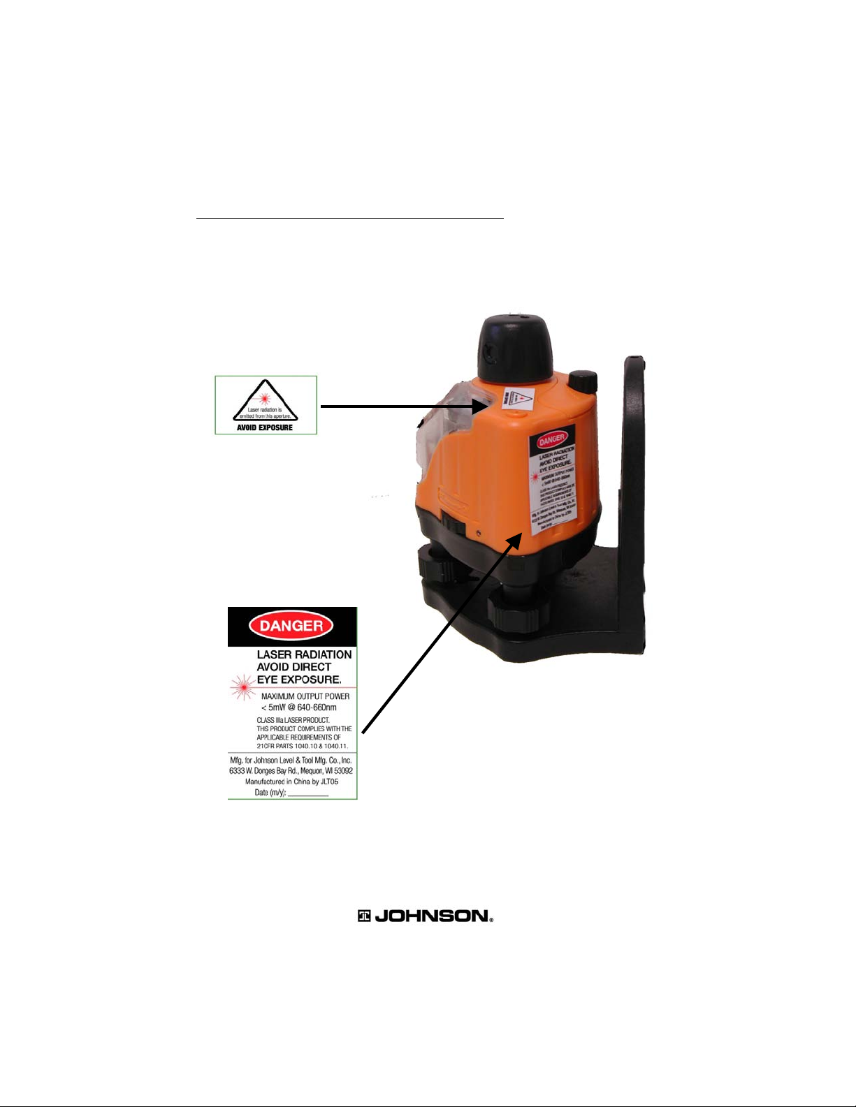
LOCATION / CONTENT OF WARNING LABELS
3
Page 4

4
WARNING!
DO NOT LOOK DIRECTLY INTO THE LIGHT BEAM.
DO NOT AIM LIGHT BEAM DIRECTLY INTO EYES.
THIS WI LL D AMA GE T HE EYES.
TECHNICAL SPECIFICATIONS
Class of laser: IIIa (class 3 protection)
Maximum power output: 5mW
Measuring range: 30m – 100m (100 ft. – 330ft.) of visible light,
depending on illumination of work area
Rotation speed: 0 – 600 rpm
Wavelength: 650nm ± 10nm
Measuring accuracy: ± 0.3mm/m (1/8" at 30 ft.)
Power supply: 4 x AA batteries
Rotary head
Laser beam exit hole
On/off switch
and speed control knob
Horizontal (level) vial “X”
Vertical (plumb) vial“Y”
Levelling screws
Base with tripod
thread and wallmounting brackets
LOCATION OF PARTS / COMPONENTS
Page 5

SAFETY IN STR UCTION S
Please read and unde rstand all the foll owing instructions prior to using thi s
laser tool. Failure to follow all the warnings below may result in bodily injury.
IMPOR TANT: Read all instructions prior to operating this laser tool and DO
NOT remove any labels from the tool.
• Use of controls or performance of procedures other than those specified
herein may result in hazardous radiation exposure.
• Do not stare directly at the laser beam.
• Do not project the laser beam directly into the eyes of others.
• Do not set up the laser tool at eye level or operate the tool on or near a
reflective surface, as the laser beam could be projected into your eyes or
the eyes of others.
• Do not place the laser tool in a manner that may cause someone to
unintentionally look into the laser beam. Serious eye injury may result.
• Do not operate the laser tool in explosive environments, i.e. in the
presence of gases or flammable liquids.
• Keep the laser tool out of reach of children and other untrained persons.
• Do no t attempt to view the laser beam through optical tools such as
telescopes as serious eye injury may result.
• Always turn the laser tool off when it is not in use or is left unattended for a
period of time. Remove the batteries when storing the tool for an
extended time to avoid damage to the tool should the batteries
deteriorate.
• Do not attempt to repair or disassemble the laser tool. Unqualified
persons attempting to repair the tool may result in serious injury.
WARNING
The tinted goggles are de signed to enhance the visibility of the laser
beam. They DO NOT offer protection to the eyes from direct
exposure of the laser beam.
5
Page 6

6
CHANGING BATTERIES AND A CTIVATIN G LASER BEAM
Unscrew the cover on the back top of the unit and insert four (4) AA batteries
(included ). To turn on, ro tate the on /off switch in the direction indicated by the
arrow.Turning the knob will increase or decrease the rotation speed.
Please Note: Used/discharged batteries are hazardous waste and must be
disposed of properly.
ASSEMBLY AND ADJUSTMENT
Open up the tripod and position it firmly on a surface that is even and as near level as
possible. For uneven surfaces and inclines, compensate by adjusting the
telescoping legs of the tripod.
Tightly screw the unit and tripod together.
Bring the unit into a level position by means of the three (3) adjusting screws and the
three (3) built-in vials.
The rotary laser can be used either with the tripod or independently.
PREPARING FOR USE
To obtain accurate measures, use the leveling screws found on the mounting base
and ensure that the bubble in each vial is perfectly centered. Utilize the speed
control knob to create a single laser point or an intermittent line or a continuous line.
Caution: Due to the 36 0° rotating feature of the laser beam, extra care must be
taken to avoid direct contact with the eyes.
Page 7

7
WARNING!
DO NOT LOOK DIRECTLY INTO THE LIGHT BEAM.
DO NOT AIM LIGHT BEAM DIRECTLY INTO EYES.
THIS WI LL D AMA GE T HE EYES.
TYPICAL APPLICATIONS
Installing drop ceilings
Installing mouldings
Page 8

8
GUARANTEE STATEMENT
The Johnson Laser Level is guaranteed against all defects in
construction and material for a period of one year. This guarantee
is limited to the replacement of defective parts upon presentation
of the sales slip. This guarantee is not applicable in the event of,
but not limited to, damage due to misuse by failing to heed the
instructions pr esent ed her ein, of unauthor ized manipulation of the
level and its attachments, or upon negligence of the
purchaser/user.
CLASS IIIa LASER
LASER DE
CLASSE IIIa
 Loading...