

Page 1
7640H-English_Manuals 12/11/13 4:18 PM Page 1
24" and 48" Waterproof Electronic
Digital Level
Model Nos. 1880-2400 & 1880-4800
Instruction Manual
Congratulations on your choice of this Digital Level. We suggest you
read this instruction manual thoroughly before using the instrument.
Save this instruction manual for future use.
©2013 Johnson Level & Tool - Rev. 1 1
Page 2
7640H-English_Manuals 12/11/13 4:18 PM Page 2
Table of Contents
1. Kit Contents
2. Features and Functions
3. Location of Parts/Components
4. Operating Instructions
5. Using the Product
6. Self-Calibration
7. Technical Specifications
8. Care and Handling
9. Product Warranty
1. Kit Contents
Description Model Nos. 1880-2400 & 1880-4800 Qty.
Electronic Digital Level 1
Instruction Manual 1
Carrying Case 1
2. Features and Functions
• IP 65 dust and waterproof
• Extremely accurate with 0.05º at 0º and 90º
• Angle inclination in 5 construction languages - units of measure
(degrees, percent, in/ft (fractional), in/ft(decimal), mm/m)
• Self-calibrate
• Automatic digit inversion for overhead measurements
• Reference function making any slope “0.0”
• Hold function locks measurement on the LCD
• Working range on angle measurement 4 x 90º
• SurroundView
®
vials reflect ambient light for easy-read
2 ©2013 Johnson Level & Tool - Rev. 1
Page 3
7640H-English_Manuals 12/11/13 4:18 PM Page 3
• Two vials read plumb and level
• Bright LCD backlight
• Audible and visual plumb and level indicators
• Shock absorbing end-caps
• Large hand grips fastened with screws
• Rigid aluminum box frame profile
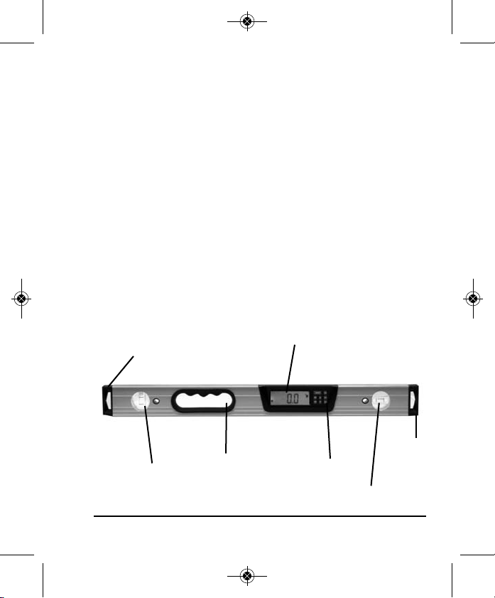
3. Location of Part/Components
LCD Display
End-cap
Window
End-cap
Plumb Vial
Hand Hole
©2013 Johnson Level & Tool - Rev. 1 3
Keypad
Level Vial
Page 4

7640H-English_Manuals 12/11/13 4:18 PM Page 4
4. Operating Instructions
IMPORTANT: It is the responsibility of the user to verify the
calibration of the instrument before each use.
Battery Installation
1. Turn the digital level off.
2. Open the battery panel by removing the battery panel screw.
3. Remove the old batteries and put in new ones.
4. Turn on the unit to see if all functions are correct.
Note:
1. Be careful to follow the polarity symbol when replacing the
batteries.
2. Take out the batteries if the digital level is not going to be used
for a long time.
Battery Panel Screw
4 ©2013 Johnson Level & Tool - Rev. 1
Page 5

7640H-English_Manuals 12/11/13 4:18 PM Page 5
5. Using the Product
Key Guide
Reference Symbol
Sound Symbol Hold Symbol
Direction
Arrow Symbol
On/Off Button
ON/OFF Button
Push this button once to turn on the digital level. Push this button
again to turn the digital level off.
RES Button
Push this button once to switch the resolution of the digital level from
0.05º to 0.1º.
Mode Button
Push this button once to switch from one unit of measure to another.
This controls which unit of measure your digital level will measure in.
Your level has the capability to measure in degrees, percentage of
millimeters/
meter Symbol
inch/feet
Symbol
Mode Button
Sound Button
Percent Symbol
Degree Symbol
Reference
Button
Battery Symbol
RES Button
Hold
Button
Calibrate Button
LCD Backlight
Button
©2013 Johnson Level & Tool - Rev. 1 5
Page 6

7640H-English_Manuals 12/11/13 4:18 PM Page 6
slope, inches/feet in fractions, inches/feet in decimal and millimeters/
meters. A symbol at the top of the LCD will show which unit of
measure you are currently in.
Push and hold this button in for 3 seconds and then release to enter
the automatic shut off mode (5 minutes or 2 hours). When the button
is held in for 3 seconds and released the LCD will show a “5”
blinking 3 times and then return to the regular display, the automatic
shut off is now set to 5 minutes. When the button is held in for
another 3 seconds and released the LCD will show a “2H” blinking
3 times and then return to the regular display, the battery symbol will
be displayed as a reminder that the digital level is now set for 2
hours. The default setting is for automatic shut off in 5 minutes.
NOTE: When the battery is low (less than 5%) the digital level will
default to 5 minute automatic shut off, the battery symbol will begin
to flash and there will be no response to pushing this button in for
3 seconds.
Reference Button
Push this button once to enter Reference Mode. The reference
function allows for setting any angle or slope to “0.0”. This is very
useful for measuring the same slope continuously during a project
or finding the difference between two slopes. To set the reference
function, position the level at the desired angle you wish to measure.
Press and release the reference button. REF will appear on the
screen while in the reference mode and the numbers will go to 0.0.
Set the level on the second surface to measure the difference
between the first and second surface. To exit this reference mode,
press the reference button again.
6 ©2013 Johnson Level & Tool - Rev. 1
Page 7

7640H-English_Manuals 12/11/13 4:18 PM Page 7
Hold Button
Push this button once to enter hold mode. Pressing this button once
will lock the current angle reading displayed on the LCD. The word
HOLD will appear at the top of the display to remind you that you are in
the HOLD function. Press this button once again to exit the hold mode.
Sound Button
Push this button once to enter the sound function mode. The sound symbol
will appear on the LCD and there will be 4 different types of sound.
1. Between 10° - 5° or 80°- 85° there is a slow beep
2. Between 4.9° - 1° or 85.1° - 89° there is a faster beep
3. Between 0.9° - 0.1° or 89.1° - 89.9° there is a rapid beep
4. 0° and 90° there is a continuous sound
Press this button again to exit the sound mode.
The sound will turn off after 20 seconds of non-movement of the
digital level. The sound will return when the digital level is moved.
Backlight Button
Push this button once to turn on the backlight function. The LCD
backlight will stay on for approximately 30 seconds with no movement
of the level. Any push of a button or movement of the level will turn the
backlight back on. To exit the backlight function, push this button again.
Calibrate Button
Push this button to enter calibration mode. See Calibration section for
more information on how to calibrate this digital level.
©2013 Johnson Level & Tool - Rev. 1 7
Page 8

7640H-English_Manuals 12/11/13 4:18 PM Page 8
Auto Shut-Off
The digital level will automatically shut-off in 5 minutes if no key is
pressed.
NOTE: This can be changed to a 2 hour automatic shut-off, please
see MODE function.
“Erro” Reading
An error reading on the LCD indicates the level is tipped too far
forward or backward to display an accurate reading.
Inclination Indication
The left and right arrows are displayed to indicate the inclination
direction of the digital level.
When the digital level is at the position of 0 degree, the horizontal
reference line will show as follows:
8 ©2013 Johnson Level & Tool - Rev. 1
Page 9

7640H-English_Manuals 12/11/13 4:18 PM Page 9
6. Self-Calibration
IMPORTANT: It is the responsibility of the user to verify the
calibration of the instrument before each use.
To Calibrate this unit:
Quick Level Calibration
1. Turn the digital level on.
2. Hold the digital level against a wall making sure the level
bubble is centered in the vial.
3. While keeping the digital level in the level position push and
hold the CAL button in for 3 seconds.
4. “CAL” will flash on the LCD indicating the digital level is in the
calibration process.
5. If the digital level is not kept stable or if the digital level is
tipped to far forward or backward, “ERRO” will appear on the
LCD. Push the Calibration Button one time to exit calibration
mode and repeat the procedure.
6. If the calibration procedure is successful, the LCD will display
“rdy”. The calibration procedure is completed and the digital
level will exit the calibration procedure automatically.
Quick Plumb Calibration
1. Turn the digital level on.
2. Hold the digital level against a wall making sure the plumb
bubble is centered in the vial.
3. While keeping the digital level in the plumb position push and
hold the CAL button in for 3 seconds.
©2013 Johnson Level & Tool - Rev. 1 9
Page 10

7640H-English_Manuals 12/11/13 4:18 PM Page 10
4. “CAL” will flash on the LCD indicating the digital level is in the
calibration process.
5. If the digital level is not kept stable or if the digital level is
tipped to far forward or backward, “ERRO” will appear on the
LCD. Push the Calibration Button one time to exit calibration
mode and repeat the procedure.
6. If the calibration procedure is successful, the LCD will display
“rdy”. The calibration procedure is completed and the digital
level will exit the calibration procedure automatically.
Calibration
1. Select a flat horizontal platform as a reference surface, like a
table surface.
2. With the digital level turned on, push the MODE button and
CAL button at the same time for 3 seconds the release.
3. The LCD will show “CAL1” indicating the digital level has
entered the calibration process.
4. Push the CAL button one time and the LCD will show a
flashing “CAL1”.
5. The LCD will then show a solid “CAL2”.
6. Rotate the level 180° putting it in the same position as it
was before.
7. Push the CAL button one time. The LCD will display a
flashing “CAL2”.
8. When the digital level is calibrated it will exit calibration
mode automatically.
10 ©2013 Johnson Level & Tool - Rev. 1
Page 11

7640H-English_Manuals 12/11/13 4:18 PM Page 11
7. Technical Specifications
Display Range 4 x 90º
Resolution 0.05º or 0.1º, 0.09% or 0.2%, 1/8",
0.125", 0.9mm/m or 2mm/m
Accuracy ± 0.05º for 0º and 90º
± 0.1º for other angles
Power Supply 2 “AAA” alkaline batteries (
Battery Life Approx. battery life 100 hours
continuous use
Working Temperature 32°F to 122°F (-10°C to +50°C)
Dimensions
24" x 1" x 2.4" (610x25x61mm)
48" x 1" x 2.4" (1220x25x61mm)
Weight 1.19 lbs (0.54kg) (1880-2400)
2.30 lbs (1.04kg) (1880-4800)
IP Class 65
8. Care and Handling
• This unit is a precision tool that must be handled with care.
• Avoid exposing unit to shock vibrations and extreme temperatures.
• Before moving or transporting the unit, make sure that the unit
is turned off.
• Remove the batteries when storing the unit for an extended time
(more than three months) to avoid damage to the unit should
the batteries deteriorate.
• Always store the unit in its case when not in use.
• Avoid getting the unit wet.
• Keep the unit dry and clean. Remove any moisture or dirt with a
soft, dry cloth.
• Do not use harsh chemicals, strong detergents or cleaning solvents
to clean the unit.
not included)
(1880-2400)
(1880-4800)
©2013 Johnson Level & Tool - Rev. 1 11
Page 12

7640H-English_Manuals 12/11/13 4:18 PM Page 12
9. Product Warranty
Johnson Level & Tool offers a limited lifetime warranty on each of its
products. You can obtain a copy of the limited warranty for a
Johnson Level & Tool product by contacting Johnson Level & Tool's
Customer Service Department as provided below or by visiting us
online at www.johnsonlevel.com. The limited warranty for each
product contains various limitations and exclusions.
NOTE: The user is responsible for the proper use and care of the
product.
It is the responsibility of the user to verify the calibration of the
instrument before each use.
For further assistance, or if you experience problems with this product
that are not addressed in this instruction manual, please contact our
Customer Service Department.
In the U.S., contact Johnson Level & Tool’s Customer Service
Department at 888-9-LEVELS.
In Canada, contact Johnson Level & Tool’s Customer Service
Department at 800-346-6682.
12 ©2013 Johnson Level & Tool - Rev. 1
 Loading...