

Johnson & Johnson Depuy Synthes Trumatch Surgical Technique

TRUMATCH®
PERSONALIZED
SOLUTIONS
with the SIGMA® High
Performance Instruments
Pin Guide System
SURGICAL TECHNIQUE
PIN GUIDE SURGICAL TECHNIQUE
The following steps are an addendum to the SIGMA®
High Performance (HP) Instruments, Fixed Reference
Surgical Technique (Cat. No. 0612-87-510).
This surgical technique provides instructions on how to
incorporate the use of the TRUMATCH® Solutions Femoral
and Tibial Pin Guides into the broader SIGMA HP
Instruments Fixed Reference Surgical Technique. The
surgeon must be familiar with the proper use of the
appropriate instruments that are necessary to complete
the operation following the use of the TRUMATCH
Solutions Femoral and Tibial Pin Guides.
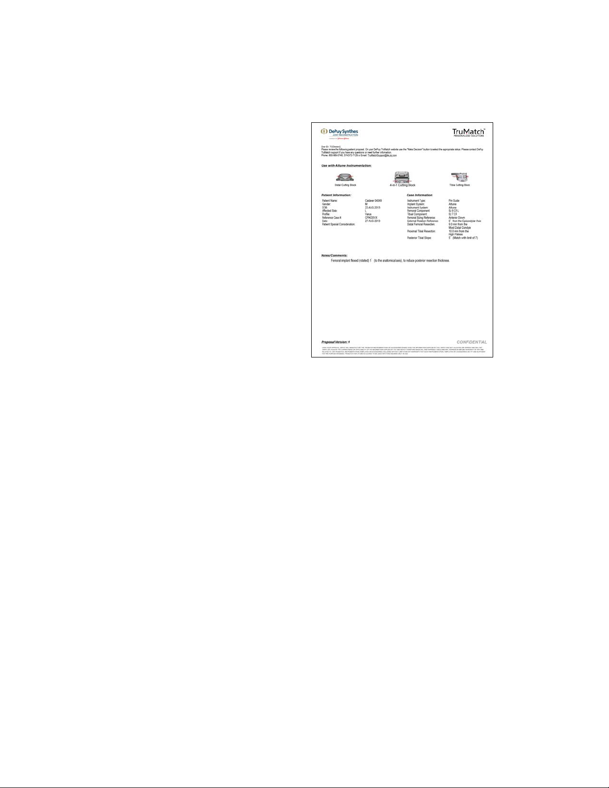
It is strongly recommended that the surgeon carefully
review the TRUMATCH Solutions Patient Proposal prior to
proceeding with the surgical procedure. The Patient
Proposal is available through the web-based, password
protected, TRUMATCH Personalized Solutions Web Portal
(www.depuysynthes.com/trumatch). The Patient Proposal
contains in-depth information utilized in the design of the
patient specific guides including, as necessary, case
specific remarks that are listed in the Notes/Comments
section.
Note: Pin Guides are only cleared for the use with
SIGMA and ATTUNE® Knee Fixed Bearing Total
Knee Implants.

BASIC TRUMATCH® SOLUTIONS PIN GUIDE
SURGICAL STEPS
SIGMA® Total Knee System steps shown.
Tibial Preparation
Step 1: Insert drill guides
and twist clockwise to
tighten.
Step 4: Placement of
anterior pins. Use of HP
uprod and rod extension
Femoral Preparation
Step 2A: Tibial guide
placement
Step 5: Twist
counterclockwise and
remove drill guide and pin
guides. Anterior pins left
in place
Step 2B: Tibial guide
alignment
Step 6: Proximal tibial
resection using HP Knee
Tibial Cutting Block
Step 3: Use of uprod
extension. Verification of
V/V alignment
Step 1: Insert drill guides
and twist clockwise to
tighten
Step 6:
Distal femoral resection
Step 2: Femoral pin
guide placement
Step 7: Use of fixed
reference guide to
position the 4-in-1
femoral cutting block
Surgical Technique TRUMATCH Personalized Solutions Pin Guides DePuy Synthes Joint Reconstruction 3
Step 3: Drill anterior and
distal pin holes, remove
drill pins and pin guide
Step 8: Use of angel wing
to verify anterior resection
Step 4: Position the distal
femoral cutting block with
anterior reference guide
Step 9: Fixation of
4-in-1 femoral cutting
block to complete femoral
resection
Step 5: Use of angel wing
to verify distal resection
level

PROXIMAL TIBIAL RESECTION
The tibial pin guide (in addition to the product packaging
label) will have patient specific identifiers: Patient Name,
Lot No., Size and Patient Anatomy (R/L). Verify the
accuracy of these identifiers prior to opening the sterile
package (Figure 1).
Note: The size information was selected pre-
operatively based on the Patient Proposal. Final
implant sizing may change due to intra-operative
assessment of implant fit and/or joint gap balance.
Figure 1
Prior to use, insert the TRUMATCH Solutions Drill Guides
(Part Number (P/N) 2004-20-925) into the two anterior
openings of the plastic tibial pin guide by twisting in a
clockwise direction until tightened (Figure 2).
Note: The TRUMATCH Solutions Drill Guides (P/N
2004-20-925) are reusable after sterilization. A
minimum of four (4) drill guides should be on hand
for a case. They are shipped separately from the
TRUMATCH Solutions Pin Guides.
For optimal handling and placement stability of the tibial
pin guide, first insert the HP Extra Medullary Tibial Uprod
(P/N 9505-01-228) into the anterior holes of the tibial pin
guide. Then slide the Rod Extension (P/N 2004-20-923)
over the distal end of the uprod. This will lengthen it to
reach the patient’s ankle. Grasp the guide using the
medial and lateral finger pads (Figure 3A). Do not grasp
the uprod or the area on which the metal drill guides are
located. (Figure 3B).
Figure 2
Figure 3A Figure 3B
4 DePuy Synthes Joint Reconstruction TRUMATCH Personalized Solutions Pin Guides Surgical Technique

With the knee flexed at 90 degrees, place the tibial resection
guide with uprod assembly onto the proximal anterior
medial aspect of the tibia and both plateaus. Avoid using
excessive force to seat the guide. Apply most of the force
anterior to posterior while holding the guide as described.
To assist in the medial/lateral positioning of the tibial pin
guide, refer to the last page of the Patient Proposal which
contains a top view of the patient’s tibial surface. It is
recommended to visualize the red line shown in the
Patient Proposal to the patient’s bone and to check
alignment with the raised line on the lateral aspect of the
tibial pin guide (Figure 4).
The planned Varus/Valgus (V/V) alignment can be confirmed
by verifying the alignment of the rod to the patient’s tibial
crest and center of the ankle (Figure 5). The rod is designed
to be parallel to the mechanical axis of the tibia regardless of
the planned tibial slope, when viewed laterally.
Note: The position of the line in the Patient Proposal
is intended to reference the medial one-third of the
tibial tubercle and not the middle of the tibial crest
(Figure 4).
Note: It is recommended to clear extraneous tissue
along the anterior medial aspect of the tibia. Soft
tissue impingement can impact the fit of the guide
and overall alignment or slope. Visualization in
assessing proper fit observed from a sagittal or side
view is helpful.
Note: To position the guide, apply most of the
pressure to the anterior aspect and the remaining
pressure to the proximal aspect of the guide. This
will help assure proper seating of the guide at the
appropriate resection level. The correct position is
found when there is minimal or no toggling/rocking
of the tibial pin guide.
Once the tibia pin guide and uprod assembly is in the
desired position, hold it in place, and secure it to the bone
by drilling two (recommended P/N 9505-02-302) pins, first
through the lateral and then the medial, drill guide pin
holes (Figure 6).
0 degree block
should be used as
slope has been
planned in the pin
placement.
Figure 4
Pins include
tibial slope.
Rod is parallel
in all cases.
Figure 5
2
1
Figure 6
Surgical Technique TRUMATCH Personalized Solutions Pin Guides DePuy Synthes Joint Reconstruction 5
 Loading...