

Page 1

1
JOHNSON
Issue date 2017-2-20 Edition 01 Doc No. SM-TM-AF-009
Revision
date
Edition time 01 Page 35
Approval Review Editor
Kyle.Schweitzer Alex Tang Dora Feng
A30/A50
Service manual
Page 2

2
Matrix Retail A30 Matrix Retail A50
A30 A50
Frame
Resistance System Internal ECB Induction Brake
Handle Bar Type Stationary
DA Arm - foam wrapped
Stationary
DA Arm
Power Supply Yes (9 ft / 2.75m) Yes (8 ft / 2.44m)
Page 3

3
Contents
CHAPTER 1: SERIAL NUMBER LOCATION...................................................................................................5
CHAPTER 2: CONSOLE BROWSE..................................................................................................................8
CHAPTER 3: TROUBLESHOOTING
3.1 Electrical Diagram..................................................................................................................................9
3.2 MCB Connections................................................................................................................................12
3.3 Trouble Shooting..................................................................................................................................14
3.3.1 Console Does Not Light Up.....................................................................................................14
3.3.2 No Console Response.............................................................................................................15
3.3.3 System Will Not Boot...............................................................................................................15
3.3.4 No Display on the Console or the Display is Dim....................................................................15
3.3.5 No RMP Display.......................................................................................................................16
3.3.6 No Resistance Or Incorrect Resistance...................................................................................17
3.3.7 Heart Rate Function Issues.....................................................................................................20
3.3.8 Pedals Slipping........................................................................................................................21
3.3.9 Knocking and Creaking Noise..................................................................................................22
3.3.10 Handlebar Keypad Failure........................................................................................................23
CHAPTER 4: PART REPLACEMENT GUIDE
4.1 Console Replacement .......................................................................................................................... 24
4.2 Heart Rate Grip Replacement .............................................................................................................. 25
4.3 Upper Handle Bar Replacement .......................................................................................................... 26
4.4 Lower Handle Bar Replacement .......................................................................................................... 27
4.5 Pedal Arm Replacement ...................................................................................................................... 28
4.6 Console Mast Covers Replacement………………………………………………………………………...29
4.7 Console Mast Replacement ................................................................................................................. 30
4.8 Link Arm Replacement ......................................................................................................................... 31
4.9 Crank Arm Replacement ...................................................................................................................... 32
Page 4

4
4.10 Front Cover Replacement .................................................................................................................. 33
4.11 Side Cover Replacement ................................................................................................................... 34
4.12 LCB&ECB Motor Replacement .......................................................................................................... 35
4.13 Elevation Motor Replacement ............................................................................................................ 36
4.14 Drive Axle Replacement………………………………………………………………………………………37
4.15 Generator Replacement………………………………………………………………………………………38
Page 5

5
CHAPTER 1: Serial Number Location
Page 6

6
CHAPTER 1: Serial Number Location
Page 7

7
CHAPTER 1: Serial Number Location
Page 8

8
CHAPTER 2: Console Browse
Please refer to XR/XER/XIR service manual to get more details.
Page 9

9
CHAPTER 3: Troubleshooting
3.1 ELECTRICAL DIAGRAM
A30
Page 10

10
CHAPTER 3: Troubleshooting
3.1 ELECTRICAL DIAGRAM
A50
Page 11

11
CHAPTER 3: Troubleshooting
3.1 ELECTRICAL DIAGRAM
A30/50 Connection
Console Connection
Page 12

12
CHAPTER 3: Troubleshooting
3.2 MCB Connections
A30 MCB
1 AC input connector
2 Incline connector
3 ECB connector
4 Console connector
Page 13

13
CHAPTER 3: Troubleshooting
3.2 MCB Connections
A50 MCB
CN1 Incline Motor Connector
CN2 Console Connector
CN3 RPM feedback wire connector
Page 14

14
CHAPTER 3: Troubleshooting
3.3.1 TROUBLESHOOTING – CONSOLE DOES NOT LIGHT UP
Symptom: No power to the console.
Solution:
1. Check the connection of the console cable at the console. Unplug the console cable from console, and
use a multi-meter to check the voltage through the console cable. Normally it should be 12VDC
between pin1 & pin8. If no voltage is present, the console cable or LCB is defective. Test voltage at
LCB, if voltage is present replace console. If not, replace LCB.
2. If the voltage through the console cable is 12VDC, the console is defective. Replace it.
FIGURE A
(Console cable’s connectors with UCB)
Page 15

15
CHAPTER 3: Troubleshooting
3.3.2 TROUBLESHOOTING- No Console Response
Symptom: The power is on, the console lights up, and a program can be started, but there is no control
over the program.
Solution:
Enter into Engineering Mode and make sure that the Machine Type is set correctly.
3.3.3 TROUBLESHOOTING- System Will Not Boot
Symptom: System Will Not Boot
The LCD has a back light, but the system does not boot up (does not display the Matrix logo)
Solution:
1. Reload the software into UCB. Test the UCB. If fail, the system crashed, replace the UCB.
3.3.4 TROUBLESHOOTING- No Display on the Console or the Display is Dim
Symptom: No Display on the Console or the Display is Dim
Solution:
1. Check the connection of the console cable at the UCB.
2. Remove the console cable from the J5 socket on the console. Pedal the machine. Set your multi-meter to
DC voltage. Place both terminals on pins 1 & 4 of the console cable. There should be a reading of more
than 5.5VDC .If voltage is more than 5.5VDC, replace the console. If voltage is less than 5.5VDC, or the
new console does not resolve the issue, replace the console cable.
3. Open the shrouds then check if all the wire harnesses are connected properly to the terminals of the LCB.
4. A50.
Unplug the generator cable from the control board, set your multi-meter to OHMS place both terminals on
pins 1 &2, pins 2 & 3, and pins 3 & 1 of the generator terminal to check if the OHMS are all equal. If the
OHM reading shown same on all 3 phases, replace the LCB. If the OHMS reading shown is not same,
replace the generator.
Page 16

16
CHAPTER 3: Troubleshooting
3.3.5 TROUBLESHOOTING – No RPM Display
Symptom: No RPM shown on the console.
Solution:
1. Bad connection between the console cable and the console: re-connect the console wire.
2. Speed sensor wire defective: Check the gap between the speed sensor and magnet on pulley. It is normal
within 5mm (Fig A).Adjust the gap if it is too large. Test sensor with Ohm meter with pin1 and pin2,pass
magnet by sensor to test.
3. Lost magnet of pulley: Re-install a new magnet (Fig. B).
4. Console defective: Replace the console set.
Page 17

17
CHAPTER 3: Troubleshooting
3.3.6 TROUBLESHOOTING – NO RESISTANCE OR INCORRECT RESISTANCE
Symptom:
1. The resistance cannot be adjusted during exercise.
2. The resistance is reverse or much too heavy.
Solution (For A30):
1. Turn on the console and check the ECB motor.
In resistance level 1, the head of steel rope directs to top right side (around 45 degree).
If the head of steel rope points to bottom left side, the resistance will be reverse. Adjust the head of steel
rope to the correct position.
Notes: in the highest resistance level, the cable should have no tension (see ECB motor replacement
section).
2. Press key “+” or “↑”to adjust the resistance.
A) If ECB motor cannot move, the resistance will not be changed. The ECB motor or console cable is
defective. Check the console cable inserted in ECB motor. Re-connect the console cable first, if still not
working, test cable for damage. If tests good, replace the ECB motor, make sure both cable ends are
seated properly.
Page 18

18
CHAPTER 3: Troubleshooting
3.3.6 TROUBLESHOOTING – No Resistance Or Incorrect Resistance
B) If the ECB motor can move, the resistance can be adjusted. If the resistance is still too heavy, check
the gap between orange block and the bottom. It should be within 1-2 mm.
If the gap is larger than 1-2 mm, the resistance will be heavier than normal. Adjust the cable to the correct
gap range.
3. If all above conditions are ok, and the resistance is still too heavy, inside magnet is defective. Replace the
ECB flywheel.
Page 19

19
CHAPTER 3: Troubleshooting
Solution (For A50):
1. Check the power resistor wire connection between the power resistor and LCB (fig-1)
2. Check the Connection wire between consoles to LCB. Try to plug off and plug on connector
(Page 13 ,CN2 )
3. Check the power resistor whether 10KΩ by multi-meter (Fig-2), if not, replace power resistor.
4. If yes, Replace. LCB.
Fig1 Fig2
Page 20

20
3.3.7 TROUBLESHOOTING-Heart Rate Function Issues
Symptom: Heart Rate Function Does Not Work or is Reading Incorrectly
Solution:
1. The heart rate grips are not connected properly or are defective.
With a multi-meter set for DC voltage, place one terminal on each of the HR grip plates. The HR grip
should give a voltage reading of between 0.5 and 2.0VDC. If the voltage is not between 0.5 and 2.0VDC,
remove the 3 screws holding the HR grip together and check the connection of the HR grip wiring.
2. The heart rate grip wiring is damaged or not connected correctly.
Check continuity of the HR grip wiring.
Place one terminal of a multi-meter set for resistance on the HR grip wiring at the HR grip, and the other
terminal on the HR grip wiring at the console. An ohm reading of around 1 should be expected. If the
reading is higher than 1,replace the HR grip wiring. Also test continuity of one terminal and to the frame
(ground) to test for a pinched wire.
3. The HR board is damaged
Remove the console. Remove the 6 screws holding the front of the console to the rear. Check the
connection of the HR board wiring to the UCB. If all the wiring is intact and has good contact, replace the
HR board.
4. The UCB is damaged.
If the HR board, HR grips, and HR grip wiring do not solve the issue, replace the UCB.
Page 21

21
3.3.8 TROUBLESHOOTING- Pedals Slipping/Belt Replacement
Symptom: Pedals Slipping or Belt Replacement
Reason:
1. The belt tension is not high enough;
2. The one way bearing is damaged.
Solution:
1. Remove the shrouds and check the belt tension. Tighten the drive belt tension if needed by moving the
spring tension clip to another hole. The generator bolt should be tightened to 85 ft / lbs.
2. If the belts are tensioned correctly, belt tension range should be 175-190HZ. The one way bearing is
damaged, replace the drive assembly.
Page 22

22
CHAPTER 3: Troubleshooting
3.3.9 TROUBLESHOOTING- Knocking or Creaking Noise
Symptom: Knocking or Creaking Noise
Solution:
a. Hardware not tight or missing.
-Inspect the unit and check for any loose hardware. Pay special attention to areas where arms meet.
Tighten hardware where found.
b. The noise is related to the internal incline.
-If the noise is present only during incline, check to make sure the Teflon washers are installed at the incline
motor connection point.
-Lubricate the guide rod of the incline motor with grease to reduce the abrasion with washer
c. The belt tension is not high enough, or the belts are too dirty.
-Remove the covers and check the belt tension.
-Tighten the drive belt tension if needed by moving the spring tension clip to another hole. It should be set to
180 ft / lbs of tension. The generator belt should be tightened to 90 ft / lbs.
-Clean the belts. If they are worn or will not clean, replace the belts.
Page 23

23
CHAPTER 3: Troubleshooting
3.3.10 TROUBLESHOOTING- handlebar keypad failure
1) Symptom:
No response from handlebar keypad, or stuck buttons.
2) Solution:
1. Disconnect handlebar keypad connection wire from back of console, and then press any button of
console. If console display normal, this is handlebar keypad problem.
a. Check if the handlebar connector on console orientation is correctly?
Check if connector is 180 degree reverses on circuit board?
b. Check if use correct handlebar connection wire?
2. Inspection the Handlebar keypad as below procedures:
a. When handlebar key does not work, firstly measure the pins with AVO meter to check if the keypad is bad.
Pic1
b. Measure the resistance of keypad: "Ω" position on AVO meter, press keypad— keypad is good if the
value <200Ω.
c. Same as step2, measure the other side keypad. Pic3.
d. If handlebar keypad is both good, next step is to judge if the handlebar cable works normally, replace the
part to try to solve it.
Pic1 Pic2 Pic3
Note: A30/A50 Quick-key wire connection
Page 24

24
CHAPTER 4: Part Replacement Guide
4.1 CONSOLE REPLACEMENT
1) Remove the 4 screws holding the console back cover to the frame (Figure A).
2) Remove the 4 screws holding the Console to the frame (Figure B).
3) Disconnect all connections from the console and remove the console from console mast. (Figure C)
FIGURE A FIGURE B
FIGURE C
4) Reverse steps to install the console.
Notes: Carefully push the wires into the console and mast until they are clear of the console / mast
connection.
Page 25

25
CHAPTER 4: Part Replacement Guide
4.2 HEART RATE GRIP REPLACEMENT
1. Remove 3 screws from the heart rate grip.
2. Separate the covers and disconnect all wires.
Page 26

26
CHAPTER 4: Part Replacement Guide
4.3 UPPER HANDLEBAR REPLACEMENT
1. Lift up on the cap by handlebar pivot joint(Figure A)
Figure A
2. Loosen the two sets screws, then you can pull the handle bar out of pivot joint.( Figure B)
Figure B
Page 27

27
CHAPTER 4: Part Replacement Guide
4.4 LOWER HANDLEBAR REPLACEMENT
1. Remove bolt from the pivot joint which is marked “1”, and remove the cap marked “2” (Figure A)
Figure A
2. Remove cap, bolt and screws to take off the Lower handlebar (Figure B)
Figure B
Page 28

28
CHAPTER 4: Part Replacement Guide
4.5 PEDAL ARM SET REPLACEMENT
1. Remove the following—lower handlebar (see section 4.4).
2. Remove the bolt shown in Fig A, remove the pedal arm.
Figure A
Page 29
29
CHAPTER 4: Part Replacement Guide
4.6 CONSOLE MAST COVERS REPLACEMENT
1. Remove the 4 screws which fix the front cover. 2 in front and 2 in rear.(Figure A&B)
Figure A
Figure B
2. Remove the 2 s
crews of the two side of rear cover to remove it(Figure C)
3.
After removing the side cover you will see the console mast. (Figure
D)
Figure C Figure D
Page 30

30
CHAPTER 4: Part Replacement Guide
4.7 CONSOLE MAST REPLACEMENT
1. Remove the following:
--console (section 4.1)
--console mast covers (section 4.6)
2. Remove the 4 bolts in front and rear. (Figure A&B)
Figure A Figure B
3. Pull off the console mast , guide the console wires to protect from damage. (Figure D)
Figure C
Page 31

31
CHAPTER 4: Part Replacement Guide
4.8 LINK ARM REPLACEMENT
1. Remove the pedal arm (see section4.5)
2. Remove the plastic cover (Figure A), then remove the link arm bolt (Figure B).
3. Remove the bolt which fix the link arm and connected tube.(Figure C&D) Then remove the link arm.
Notes: torque for the link arm bolt is 800kgf.cm.
Figure C&D
4. Reverse steps to replace link arm.
Page 32

32
CHAPTER 4: Part Replacement Guide
4.9 CRANK REPLACEMENT
1. Remove the link arm(see section4.8)
2. After remove the link arm, you can see the crank. Remove the nut and screws to remove the plastic cover
of the crank. (Figure A)
3. After remove the cover, remove the crank arm bolt to remove the crank, a two jaw puller might be needed.
(Figure B)
Figure A Figure B
4. The torque on crank bolts must be 800kgf.cm (Figure C & Figure D)
Figure C Figure D
Page 33

33
CHAPTER 4: Part Replacement Guide
4.10 FRONT COVER REPLACEMENT
1. Remove the console mast covers( section4.6).
2. Remove the two screws to take off the front cover. (Figure A)
3. Reverse steps to replace front cover.
Figure A
Page 34

34
CHAPTER 4: Part Replacement Guide
4.11 SIDE COVER REPLACEMENT
1. Remove the following:
--console mast covers (see section4.6)
--Front cover (see section4.10)
--crank arms (see section4.9)
2. Remove the 9 screws which fix the side cover.
3. Remove the 2 screws as Fig B.
4. Reverse steps to install side cover.
Figure A Figure B
Page 35

35
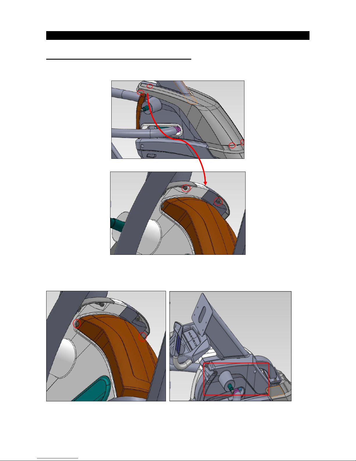
CHAPTER 4: Part Replacement Guide
4.12 LCB AND ECB MOTOR REPLACEMENT
1. Remove the following:
--console (section4.1)
--console mast covers (section4.6)
2. Remove the 2 screws to replace LCB. (Fig A)
3. Remove the 4 screws to replace the ECB motor (Fig B).
Figure A Figure B
Note:
Note: the circuit board could become damaged during this procedure from electrostatic discharge. We
recommend wearing an ESD wrist strap.
Page 36

36
CHAPTER 4: Part Replacement Guide
4.13 ELEVATION MOTOR REPLACEMENT
1. Remove the following:
-
-console (section4.1)
-
-console mast covers (section4.6)
2.
Remove 4 bolts, except H38, the torque of other bolts should be 500kgf.cm, Fig A&B &C.
Figure A & B & C
3. Reverse steps to install elevation motor.
Notes: when install H38 bolt,please twist negetive direction ha
lf round.
 Loading...