

Page 1

ZFR1812 Wall Mount Wireless Field Bus Router
Installation Instructions
MS-ZFR1812-x
Part No. 24-10325-45, Rev. A
Issued April 2016
Application
Use the ZFR1812 Wireless Field Bus Router only to
provide an input to equipment under normal
operating conditions. Where failure or malfunction of
the ZFR1812 Router could lead to personal injury or
property damage to the controlled equipment or
other property, additional precautions must be
designed into the control system. Incorporate and
maintain other devices, such as supervisory or
alarm systems or safety or limit controls, intended to
warn of or protect against failure or malfunction of
the ZFR1812 Router.
IMPORTANT: The ZFR1800 Series Wireless Field
Bus System is not designed or intended for use in
mission-critical or life/safety applications.
A ZFR1812 Wireless Field Bus Router is used with
Advanced Application Field Equipment Controllers
(FACs), Field Equipment Controllers (FECs), Input/
Output Modules (IOMs), and Variable Air Volume
Modular Assembly (VMA) Series field controllers.
The ZFR1812 Router provides a wireless interface
between:
• a field controller and the supervisory controller (b
ans of a ZFR1810 Coordinator)
me
• a field controller and associated WRZ Seri
Wireless Room
Additionally, the ZFR1812 Wireless Field Bus Router
can be used as a repeater in WRZ-7860-0 One-to-One
Wireless Room Temperature Sensing System. For
more information, refer to the WRZ Series One-to-One
Wireless Room Sensing System Technical Bulletin
(LIT-12011641).
Up to nine WRZ Series Sensors can be associated
with a single field controller. In multi-sensor
applications, the ZFR1812 Router passes all the
sensor data to an FAC, FEC, IOM, or VMA controller,
which can be configured to either average the sensors’
input or select the highest or lowest sensed condition
for control of the target zone.
Sensors
y
es
A ZFR1812 Router is powered directly from the
connected field controller’s 15 VDC output.
The ZFR812 Router is also included in the Repeater
Accessory Kits, MS-ZFRRPTK-H1 or MS-ZFRRPTKH2. These kits include a 24 VAC to 15 VDC converter
power supply for stand-alone operation. As a repeater,
the ZFR1812 extends the range and strengthens the
wireless mesh network.
Refer to the ZFR1800 Series Wireless Field Bus
System Technical Bulletin (LIT-12011295) or the
ZFR1800 Series Wireless Field Bus System Quick
Reference Guide (LIT-12011630) for information on
commissioning and configuring a ZFR1800 Series
Wireless Field Bus System for operation.
North American Emissions Compliance
United States
Compliance Statement (Part 15.19)
This device complies with Part 15 of the FCC Rules.
Operation is subject to the following two conditions:
1. This device may not cause harmful interference
an
d
2. This device must accept any interference
received, including interference that may cause
undesired operation.
Warning (Part 15 .21)
Changes or modifications not expressly approved by
the party responsible for compliance could void the
user’s authority to operate the equipment.
Canada
Industry Canada Statement
The term IC before the certification/registration
number only signifies that the Industry Canada
technical specifications were met.
Le terme « IC » précédant le numéro d'accréditation/
inscription signifie simplement que le produit est
conforme aux spécifications techniques d'Industry
Canada.
,
ZFR1812 Wall Mount Wireless Field Bus Router Installation Instructions
1
Page 2
Installation
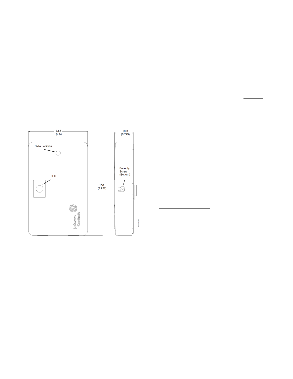
Figure 1: ZFR1812 Wireless Field Bus Router,
Physical Features and Dimensions, mm (in.)
Follow these guidelines when installing a
ZFR1812 Router:
• Transport the ZFR1812 Router in the original
container to minimize vibration and shock damage.
• Do not drop the ZFR1812 Router or subject it to
physical shock.
Materials and Special Tools Needed
• A 1.5 mm (1/16 in.) Allen wrench or a Johnson
Controls® T- 4000-119 Allen-He ad Adjustment Tool
is required for tightening or loosening the security
screw
Dimensions
See Figure 1 for physical features and dimensions of
the ZFR1812 Router.
The ZFR1812 can be mounted directly to drywall with
drywall anchors. Both the standalone and repeater kit
versions of the ZFR1812 include a 10 foot long RJ12
cable hardwired to the device. The Repeater Kit
versions (the ZFRRPTK-H1 and ZFRRPTK-H2)
provide additional flexibility for mounting such as a
separate power supply. ZFR1812s can be flush
mounted to a wall or ceiling, or mounted on a 4x4 box
using a standard mudplate. When mounting the
ZFR1812 Router to an enclosure, mount it to the top,
bottom, or side of the enclosure. For floor mount
unitary equipment, mounting on top where books or
other items may be placed is not ideal. See Location
Considerations.
Mounting Directly to Drywall with Drywall Anchors
- ZFR1812
1. Separate the plastic base and circuit board
assembly (cover). Do not remove the security
screw from the cover. See Figure 2.
IMPORTANT: The label showing the unit MAC
address is on the plastic base of the unit. Be sure to
keep the plastic base and circuit board assemblies
together so the correct MAC address is shown.
Mounting
Note: These instructions are for mounting new
ZFR1812s rather than retrofitting factory-mounted
routers.
2. Determine where to secure the plastic base to the
surface using the mounting holes and supp lie d
screws. A template (Figure 11) is provided at the
end of this document to help you place the
mounting holes.
3. Set the DIP switches. (See
Setup and Adjustments
4. Reattach the circuit board assembly in the plastic
base being careful not to pinch the a t tached RJ-12
cable.
5. Tighten the security screw to prevent tampering
using a 1.5 mm (1/16 in.) Allen wrench or a
Johnson Controls® T-4000-119 Allen-Head
Adjustment Tool. Use caution when tightening the
screw to avoid stripping the plastic threads in the
ZFR1812.
Mounting the ZFRRPTK-H1
The ZFRRPTK-H1 is intended for flush wall mount or
ceiling mount applications. In addition to the ZFR1812,
it includes a power supply, a 10 ft RJ-12 cable for
connecting the power supply, and an adapter to
connect the power supply to the RJ-12 cable.
).
ZFR1812 Wall Mount Wireless Field Bus Router Installation Instructions
To mount the ZFRRPTK-H1:
1. Separate the plastic base and circuit board
assembly (cover). Do not remove the security
screw from the cover. See Figure 2.
2
Page 3
IMPORTANT: The label showing the unit MAC
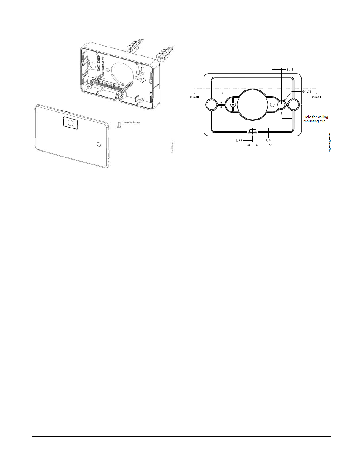
Figure 2: ZFR1812 Wireless Field Bus Router,
with Plastic Base and Circuit Board Assy
Separated
Figure 3: ZFR1812 Wireless Field Bus Router,
with Plastic Base Hole for Ceiling Mount
address is on the plastic base of the unit. Be sure to
keep the plastic base and circuit board assemblies
together so the correct MAC address is shown.
2. Decide whether you are mounting on a wall or
ceiling.
a. For flush wall mount applications, determine
where to secure the plastic base to the surface
using the mounting holes and supplied screws.
A template (Figure 1 1) is provided at the end of
this document to help you place the mounting
holes.
b. For ceiling mount applications, mount the
ZFR1812 to the grid between the tiles. Ther e
are a number of ceiling mounting clips
available from third parties which can be used.
Make sure to match the clip you purchase to
the grid in the location where you are doing the
installation. Ceiling grid dimensions and offsets
vary, so using an incorrectly sized clip may
prevent mounting the ZFR1812 flush for a
professional appearance. A hole is provided in
the base of the assembly for this purpose
(Figure 3).
IMPORTANT: If you are using a ceiling mounting clip
you must make sure that no part of the clip makes
contact with the circuit board assembly when installed.
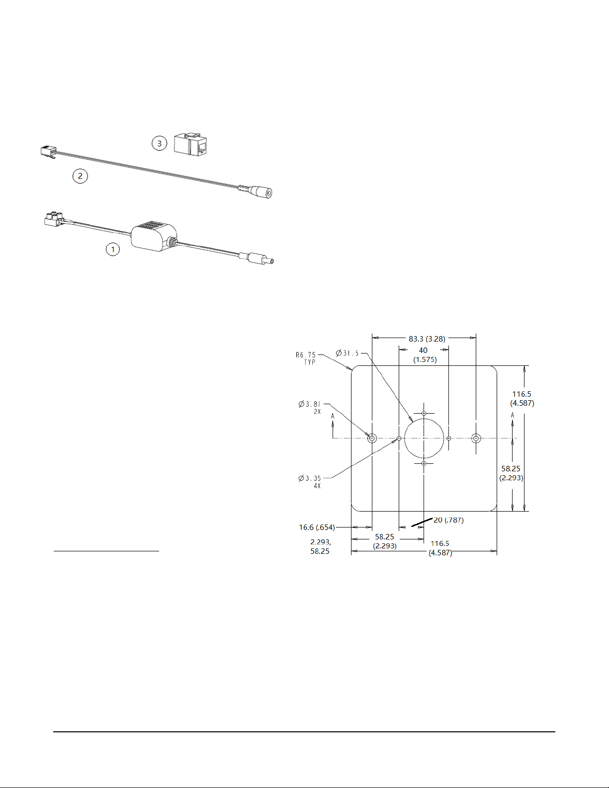
3. Assemble the external power and adapters as
necessary (Figure 4).
a. The 24 VAC to 15 VDC power supply (1) uses
screw terminals to attach to a 24 volt source.
b. The adapter connects the 15 VDC output of the
power supply to an RJ12 adapter (2). Plug this
adapter directly to the cable coming from the
ZFR1812 through a connector (3 ).
c. This connector (3) is then used to connect to
the 10 ft RJ-12 cable which is attached to the
ZFR.
Note: Any inline adapter used to extend the
connection of the ZFR1812 to a controller or po wer
must be a straight through adapter instead of
crossover.
4. Set the DIP switches. See Setup and Adjustments
5. Reattach the circuit board assembly in the plastic
base.
.
ZFR1812 Wall Mount Wireless Field Bus Router Installation Instructions
3
Page 4
6. Tighten the security screw to prevent tampering
Figure 4: Power supply and adapters
Figure 5: ZFR1812 Wireless Field Bus Router,
Wall Plate Dimensions mm (in.)
using a 1.5 mm (1/16 in.) Allen wrench or a
Johnson Controls® T-4000-119 Allen-Head
Adjustment Tool. Use caution when tightening the
screw to avoid stripping the plastic threads in the
ZFR1812.
Mounting in a Wall Plate - ZFRRPTK-H2
Note: The wall plate is intended to attach to a
mudplate rather than directly to the wall.
7. Assemble the external power and adapters as
necessary (Figure 4). Note that the power supply
can be secured in an electrical box with the
provided two-sided tape. An electrical box is not
included with the kit.
a. The 24 VAC to 15 VDC power supply (1) uses
screw terminals to attach to a 24 volt source.
b. The adapter connects the 15 VDC output of the
power supply to an RJ12 adapter (2). This
adapter can be plugged directly into the RJ12
jack on the ZFR1812 or connected to a
connector (3).
c. This conn e cto r (3 ) is then used to connect to
the 10ft RJ12 cable which is attached to the
ZFR1812.
8. Mount the wall plate with ZFR1812 in the selected
location using standard box screws. Be sure to
leave enough slack in the cable so you can still pull
the ZFR1812 if you need to change the DIP
switches.
1. Separate the plastic base and circuit board
assembly (cover). Do not remove the security
screw from the cover. See Figure 2.
IMPORTANT: The label showing the unit MAC
address is on the plastic base of the unit. Be sure to
keep the plastic base and circuit board assemblies
together so the correct MAC address is shown.
2. Attach the plastic base to the supplied wall plate.
Figure 5 shows the wall plate dimensions.
3. Connect the external cable assembly to the 6-pin
modular receptacle.
4. Set the DIP switches. (See
Setup and Adjustments
5. Reattach the circuit board assembly in the plastic
base.
6. Tighten the security screw to prevent tampering
using a 1.5 mm (1/16 in.) Allen wrench or a
Johnson Controls® T-4000-119 Allen-Head
Adjustment Tool. Use caution when tightening the
screw to avoid stripping the plastic threads in the
ZFR1812.
)
ZFR1812 Wall Mount Wireless Field Bus Router Installation Instructions
4
Page 5

The preferred orientation for the ZFR1812 Router is in
Figure 6: ZFR1812 Mounted in Wall Plate
a horizontal orientation with the green LED at the top. If
you feel that you are not able to get proper signal
strength, you can rotate the device 90 degrees on its
plastic wall plate. See Figure 6.
Location Considerations
Follow these guidelines when locating a ZFR1812
Router within a ZFR1800 Series System.
• Locate the ZFR1812 Router so that it is easily
accessible.
• For best signal transmission, mount the ZFR1812
Router in an unobstructed location below (and
clear of) any pipes, duct work, or other metal
obstructions by at least 50 mm (2 in.).
• Due to the nature of the radio frequency waves, a
wireless device may have significantly different
signal strengths if its position changes relative to
another wireless device or if its environment
changes.
• Locate the ZFR1812 Router in line-of-sight with as
many ZFR1812 Routers and WRZ Sensors as
possible.
• Do not mount the ZFR1812 Router in recessed
areas, metal enclosures, or shelving units.
Note: For detaile d information on location guidelines
for a ZFR1800 Series system, and for estimating the
number of ZFR1812 Routers needed as repeaters for
extending wireless transmission range, refer to the
ZFR1800 Series Wireless Field Bus System Technical
Bulletin (LIT-12011295).
Wireless Signal Transmission Considerations
Line-of-sight transmission ranges between a
ZFR1810 Coordinator, ZFR1812 Router, and a
WRZ Sensor can be less than the maximum distances
shown in Table 1. The effective transmission range for
indoor applications varies because of wireless signal
absorption and reflection due to metal obstructions,
walls (or floors), and furniture found in typical building
interiors.
Table 1: Indoor Line-of-Sight Transmission
Ranges
Range Type Transmission Distance
ZFR1810
Coordinator,
ZFR1812 Router
Recommended 15.2 m (50 ft) 15.2 m (50 ft)
Maximum 76.2 m (250 ft) 30 m (98 ft)
WRZ Series
Sensor
Wiring
Wiring Considerations and Guidelines
IMPORTANT: Do not connect supply power to the
ZFR1812 Router before finishing wiring and
checking all wiring connections. Short circuits or
improperly connected wires may result in permanent
damage to the Router.
IMPORTANT: Use copper conductors only. Make
all wiring in accordance with local, national, and
regional regulations. The ZFR1812 Router is a
low-voltage (less than 30 VAC) device. Do not
exceed the ZFR1812 Router’s electrical ratings.
IMPORTANT: Prevent any static electric discharge
to the ZFR1812 Router . Static electric discharge can
damage the ZFR1812 Router and void any
warranties.
IMPORT ANT: Do not connect the ZFR1812 Router
to the power supply before setting the PAN OFFSET
switches.
Wiring with an FEC or VMA16 Series Field Controller
Connect the ZFR1812 Router to the field controller as
shown in Table 2. This connection provides both power
and communication to the ZFR1812 Router.
Note: When using a field controller in a wireless field
bus network, ensure that the DIP switch for Address
128 is set to the ON position.
ZFR1812 Wall Mount Wireless Field Bus Router Installation Instructions
5
Page 6

Figure 7: Pin Number Assignments for
RJ-12 Jack
(15 VDC)
SA or FC Bus
-
Bus and Power Common
Power
(15 VDC)
(RJ-12 Mod ul ar Jack)
Bus and Power Common
p
Table 2: Connecting the ZFR1812 Router to a Field Controller
Field
Controller
Model
Plug the ZFR1812 Router
Connector Cable into the
Following Jack on the Field
Controller:
Connection Points for the
Bluetooth® CVT
Commissioning Interface
and Other SA Bus Products
Use This
Communications Port
between WEFC and
1
Wired IOMs, WRZ
Sensors, or VFDs:
FAC26 FC Bus RJ-12 Jack SA Bus RJ-12 Jack SA Bus Terminals
FAC36 FC Bus RJ-12 Jack SA Bus RJ-12 Jack SA Bus Terminals
FEC16 FC Bus RJ-12 Jack SA Bus RJ-12 Jack SA Bus Terminals
FEC26 FC Bus RJ-12 Jack SA Bus RJ-12 Jack SA Bus Terminals
2,3
IOM17
2,3
IOM27
2,3
IOM37
IOM472,
VMA1615/30 FC Bus RJ-12 Jack SA Bus RJ-12 Jack SA Bus Terminals
1. SA Bus Products include the DIS1710 Local Controller Display, the MS-BTCVT-1 Wireless
Commissioning Converter, and the NS Series (hard-wired) Network Sensors, Balancing Sensors, and
Discharge Air Temperature Sensors.
2. IOMs cannot be used in wireless mode to extend the IO of a field controller. You must always hardwire
IOMs to their host field controller.
3. Do not connect any device to the SA Bus/FC Bus terminal block when using the IOM with a ZFR1812.
SA/FC Bus RJ-12 Jack Not available in wireless mode.
Use CCT with ZFR Dongle.
SA/FC Bus RJ-12 Jack Not available in wireless mode.
Use CCT with ZFR Dongle.
SA/FC Bus RJ-12 Jack Not available in wireless mode.
3
SA/FC Bus RJ-12 Jack Not available in wireless mode.
Use CCT with ZFR Dongle.
Use CCT with ZFR Dongle.
N/A
N/A
N/A
N/A
For further information on how to set up a field
controller to work with the ZFR1812 Router, refer to the
following documents:
• FAC3611 Advanced Application Field Equipment
Controller Installation Instructions (Part No. 2410143-470)
• FEC16 Field Equipment Controller Installation
Instructions (Part No. 24-10143-136)
• FEC26 Field Equipment Controller Installation
Instructions (Part No. 24-10143-144)
• IOM17 and IOM27 Input/Output Modules
Installation Instructions (Part No. 24-1044-76)
• IOM37 Input/Output Module Installation
Instructions (Part No. 24-1044-84)
• IOM47 Input/Output Module Installation
Instructions (Part No. 24-1044-92)
• VMA16 Series Variable Air Volume Controllers
Installation Instructions (Part No. 24-10143-20)
Sensor, SA Bus, or FC Bus Port
Power
6
5
4
3
2
1
SA or FC Bus +
FIG:RJ_
inout
ZFR1812 Wall Mount Wireless Field Bus Router Installation Instructions
6
Page 7

The value equals the sum of the numbers set to ON.
Figure 8: Connecting an IOM to a
Wireless-Enabled VMA1615/1630 Field Controller
Figure 9: Wiring a Discharge Air Net sensor , Zone
Netsensor with Terminal Block, or IOM to a
Wireless-Enabled VMA1615/1630 Field
Controller
For example, if the DIP switches labeled 1, 4, and 8
are set to ON, the PAN Offset value is 13
(1 + 4 + 8 = 13).
When selecting a PAN Offset value for a wireless
system:
• Use a unique PAN Offset value for each wireless
mesh network at a job site.
• Use the same PAN Offset value for each wireless
device in a wireless mesh network—the
ZFR1810 Coordinator and each associated
ZFR1812 Router and WRZ Sensor.
• If, after setting the PAN Offset value you find that
you are unable to communicate with the desired
network, it may help to toggle the DIP switches to
ensure a good connection. Power down the
ZFR1812 and toggle the switches (all off, then all
on) and then set the switches to the desired PAN.
Restore power to the ZFR1812 and see that it joins
the correct network.
• If the ZFR1812 misread the dip switches, it might
become the child of another network and use up an
available child slot in a device you did not expect. If
this situation occurred, a reform on the incorrect
network should clear up the now unusable child
address.
Setup and Adjustments
IMPORTANT: Ensure that the PAN OFFSET
switches are set to the same value for each
ZFR1810 Coordinator, ZFR1812 Router, and
WRZ Sensor in a mesh network.
IMPORT ANT: Do not connect the ZFR1812 Router
to the power supply before setting the PAN OFFSET
switches.
IMPORTANT: On the MS/TP Address switch block
of the associated FEC/IOM/VMA16 Field Controller,
set switch 128 to ON for use with a ZFR1812
Router.
Set the P AN Offset value of the ZFR1812 Router using
the DIP switches (located on the back of the cover) to
configure the ZFR1812 Router to communicate on the
wireless mesh network. See Figure 1 and Figure 10.
Note: On some date code labels, the switch position
numbers on the bottom of the DIP switch are reversed.
In either case, the switch positions are always read
right to left.
ZFR1812 Wall Mount Wireless Field Bus Router Installation Instructions
7
Page 8

Figure 10: Sample DIP Switch Settings
Wireless transmissions between ZFR1810
Coordinators and ZFR1812 Routers occur as needed.
Wireless transmissions between ZFR1812 Routers
and WRZ Sensors occur approximately every 60
seconds or when the occupancy button on the WRZ
Sensor is pressed. Refer to the WRZ Series Wireless
Room Temperature Sensors Installation Instructions
(Part No. 24-10332-2) for more information.
Approximately once every 10 seconds, the Signal
Strength LED flashes to indicate the strength of the
signal received from neighboring devices. See Table 3.
Note: The Signal Strength LEDs on all the ZFR1812
routers in a network extinguish after approximately
2 hours of normal operation, making the ZFR1812 less
distracting when installed in an open area. To re-enable
the ZFR1812 LEDs for troubleshooting purposes,
perform a scan using the ZFR Checkout Tool (ZCT).
Alternatively, push the Network Optimize/Reform Push
Button on the ZFR1810 coordinator for 0 to 5 seconds.
Note that if you press this button more than 5 seconds,
a Network Optimize or Reform is initiated.
Refer to the ZFR1800 Series Wireless Field Bus
System Technical Bulletin (LIT-12011295) for more
information on determining the signal strength between
ZFR1800 Series devices in your application.
Troubleshooting
Use the Status LED (see Figure 1) along with the
information in Table 3 to troubleshoot the ZFR1812
Router.
Wireless Signal Strength
A wireless signal strength indication LED displays the
reception strength of the transmissions between the
ZFR1810 Coordinators, ZFR1812 Routers, and the
WRZ Series Sensors. This LED helps determine the
network connectivity status when selecting locations for
the devices during system installation.
ZFR1812 Wall Mount Wireless Field Bus Router Installation Instructions
8
Page 9

WRZ-SST-120 Wireless Sensing System Tool
Use the WRZ-SST-12 0 Wireless Sensing System Tool
with a WRZ Series Sensor as a site survey tool to
determine the wireless signal strength between a
ZFR1810 Coordinator and a ZFR1812 Router or
between two ZFR1812 Routers. Refer to the
WRZ-SST-120 Wireless Sensing System Tool
Installation Instructions (Part No. 24-10563-12) for
more information on testing signal strength in your
application.
Table 3: ZFR1812 Router Status LED
Name Visual
Descriptions
Indication of:
General
Operation
Signal
Strength
Indication
Network
Reform
Network
Ping
Normal
operation
Wireless signal
strength
1
Operation
during network
reform
Wireless node
function in the
network
OFF Steady = No power (or normal operation for more than 2 hours).
OFF Steady with 1 Flash every 10 seconds = ZFR1812 Router is not a member of a
wireless network, invalid PAN OFFSET setting, no ZFR1810 Coordinators or ZFR1812
Routers in area.
ON Steady with Signal Strength displayed once every 10 seconds = ZFR1812 Router
is a member of a wireless network.
OFF Steady with Signal Strength displayed once every 10 seconds = Wireless network
is actively communicating, but ZFR1810 Coordinator cannot be reached (for example,
coordinator lost power).
3 Flashes - Excellent
2 Flashes - Good
1 Flash - Weak
OFF for 3 seconds - None
Rapid Flashes for 5 minutes = rapid flashes occur for up to 5 minutes:
• when the Reform Network option is initiated to the network, the ZFR1812 Router
disconnects itself from the network
• when the PAN OFFSET is changed on the ZFR1812 Router
• when the PAN OFFSET is changed on the ZFR1812 Router after it has already joined
another PAN
• when the Channel Mask in the ZFR1810 is changed from CCT
Network pings provide a means of physically locating connected devices. There are two
methods with different use cases:
1) Use ZFR Checkout T ool (ZCT) to ping an address. The LED on the connected ZFR1812
blinks, indicating the device mapped to that specific MS/TP address.
2) Press the Occupancy push button on a WRZ Network Sensor. The ZFR1812 connected
to the paired device blinks. This blinking response can be used to validate switch settings
on the sensor during installation.
1. The Signal Strength LEDs on all the ZFR1812 Routers in a network extinguish after approximately 2 hours of normal
operation, making the ZFR1812 less distracting when installed in an open area. To re-enable the ZFR1812 LEDs for
troubleshooting purposes, perform a scan using the ZCT or push the Network Optimize/Reform Push Button on the
ZFR1810 Coordinator.
ZFR1812 Wall Mount Wireless Field Bus Router Installation Instructions
9
Page 10

Repair Information
If the ZFR1812 Wireless Field Bus Router fails to
operate within its specifications, replace the unit. For a
replacement ZFR1812 Route r, contact the nearest
Johnson Controls® representative.
Accessories
See Table 4 for information on accessories for the
ZFR1812 Router . Use the ZFRRPT -H1/H2 repeater kits
for below ceiling repeater applications where the router
is in visible space. Mounting the repeater in an open or
visible space increases the transmission distances for
improved wireless coverage.
Table 4: Accessories
Product Code
Product Description
Number
MS-ZFRRPT-0 Optional Repeater Accessory for use with ZFR1811 Routers as a repeater. Includes power supply
MS-ZFRRPTK-H1 ZFR1812-0 wireless router repeater kit. Includes ZFR1812 router, 24 VAC to 15 VDC power supply,
MS-ZFRRPTK-H2 ZFR1812-0 wireless router repeater kit. Includes ZFR1812 router, 24 VAC to 15 VDC power supply,
WRZ-SST-120 Wireless Sensing System Tool. Requires WRZ Series Sensor to function as a site survey tool for
ZFR-USBHA-0 USB Dongle with ZFR Driver provides a wireless connection through the CCT to allow wireless
(20 to 28 VAC or 16 to 30 VDC input power and 12 VDC output power).
The ZFRRPT-0 with ZFR1811-1 combination is used for above ceiling repeater applications or
wherever mounting of the ZFR router is better facilitated using a ½ Inch conduit EMT connector.
RJ-12 cable for power extension, and mounting hardware.
Use the ZFRRPT-H1 for flush wall mount or ceiling mount applications.
RJ-12 cable for power extension, mounting hardware, and mounting plate for electrical box.
Use the ZFRRPT-H2 for mounting directly to a single or double gang electrical box. The electrical box is
not included with the kit.
ZFR1800 Wireless Field Bus System, or for WRZ-7860-0 One-to-One Room Temperature Sensing
System.
commissioning of the wireless-enabled FAC, FEC, IOM, and VMA16 controllers. The USB ZFR Dongle
is also used with the ZFR Checkout To ol used to troubleshoot and validate ZFR wireless meshes using
a laptop computer.
ZFR1812 Wall Mount Wireless Field Bus Router Installation Instructions
10
Page 11

Technical Specifications
ZFR1812 Wireless Field Bus Router (Part 1 of 2)
Product Code Number MS-ZFR1812-0: Field Equipment, Wireless Interface, Surface Mount, includes
hardwired 10 foot RJ-12 cable.
MS-ZFRRPTK-H1: ZFR1812-0 wireless router repeater kit. Includes ZFR1812 router, 24
VA C to 15 VDC power supply, RJ-12 cable for power extension, and mounting hardware.
MS-ZFRRPTK-H2: ZFR1812-0 wireless router repeater kit. Includes ZFR1812 router, 24
VA C to 15 VDC power supply , RJ-12 cable for power extension, mounting hardware, and
mounting plate.
Power Supply Input 8 to 18 VDC, 15 VDC Nominal. Provided from the FC/SA BUS RJ-12 jack on the FEC or
VMA16 controller or from 24 VAC to 15 VDC power supply.
The power converter for the repeater power supply has a flexible input power range and
provides regulated 12 VDC output.
Input power:
• 20–28 VAC at 78–62 mA (maximum)
• 16–30 VDC at 45–28 mA (maximum)
• Output power: 12 VDC regulated at 500 mA maximum.
Current Consumption 90 mA maximum
Addressing DIP Switches, Field Adjustable.
Wireless Band Direct-Sequence Spread-Spectrum, 2.4 GHz ISM Bands
Transmission Power 10 mW Maximum
Transmission Range 76.2 m (250 ft) Maximum Indoor Line-of-Sight
15 m (50 ft) Recommended Indoor
Ambient Conditions Operating: 0 to 50°C (32 to 122°F), less than 90% RH, Noncondensing
Non-Operating (Storage): -40 to 80°C (-40 to 176°F), less than 95% RH,
Noncondensing
Maximum Dew Point Temperature: 30°C (86°F)
Condensation: Recovers after 30 minute dry time
Materials White PC/ABS Cycoloy
Terminations RJ-12 plug for connection to FEC or VMA16 FC/SA Bus jack
Dimensions 61 x 100 x 20.5 mm (5-3/8 x 3-15/16 x 3/4 in.)
Mounting Hardware Screw mounted
Shipping Weights ZFR1812: 0.113 kg (.25 lb)
Repeaters: 227 kg (.50 lb)
ZFR1812 Wall Mount Wireless Field Bus Router Installation Instructions
11
Page 12

ZFR1812 Wireless Field Bus Router (Part 2 of 2)
Compliance United States:
Intended for Connection to an NEC Class 2 Power Source;
UL 916 Energy Management
Plenum rated per UL1995 UL94-5VB Flammability Rating
FCC Compliant to CFR47, Part 15, Subpart B, Class A
Transmission Complies with FCC Part 15.247 Regulations for Low Power Unlicensed
Transmitters
Transmitter Identification ZFR1812-0: FCC: TFB-MATRIXL;
Transmitter Identification ZFR1812-1: FCC: OEJ-WRZRADIO;
Canada:
CAN/CSA C22.2 No. 205, Signal Equipment
Industry Canada (IC) Compliant to Canadian ICES-003, Class B Limits
Industry Canada (IC) RSS-210
Transmitter Identification ZFR1810-0: 5969A-MATRIXLP
Transmitter Identification ZFR1810-1: 279A-WRZRADIO
Australia and New Zealand:
RCM Mark, Australia/NZ Emissions Compliant
Europe:
CE Mark – Johnson Controls, Inc., declares that this product is in compliance with the
essential requirements and other relevant provisions of the RED Directive.
The performance specifications are nominal and conform to acceptable industry standard. For application at conditions beyond these
specifications, consult the local Johnson Controls office. Johnson Controls, Inc. shall not be liable for damages resulting from misapplication or
misuse of its products.
European Single Point of Contact: NA/SA Single Point of Contact: APAC Single Point of Contact:
JOHNSON CONTROLS
WESTENDHOF 3
45143 ESSEN
GERMANY
JOHNSON CONTROLS
507 E MICHIGAN ST
MIL WAUKEE WI 53202
USA
JOHNSON CONTROLS
C/O CONTROLS PRODUCT MANAGEMENT
NO. 22 BLOCK D NEW DISTRICT
WUXI JIANGSU PROVINCE 214142
CHINA
ZFR1812 Wall Mount Wireless Field Bus Router Installation Instructions
12
Page 13

ZFR1812 Wall Mount Wireless Field Bus Router Installation Instructions
Metasys® and Johnson Controls® are registered trademarks of Johnson Controls, Inc.
All other marks herein are the marks of their respective owners. © 2016 Johnson Controls, Inc.
Building Efficiency
507 E. Michigan Street, Milwaukee, WI 53202
Figure 11: ZFR18 12 Mounting Template - Scale 1.000
Published in U.S.A. www.johnsoncontrols.com
13
 Loading...