

Page 1

ZFR1810 Wireless Field Bus Coordinator
Installation Instructions
MS-ZFR1810-x
Application
IMPORTANT: Use the ZFR1810 Wireless Field
Bus Coordinator only to provide an input to
equipment under normal operating conditions.
Where failure or malfunction of the ZFR1810
Coordinator could lead to personal injury or pr operty
damage to the controlled equipment or other
property, additional precautions must be designed
into the control system. Incorporate and maintain
other devices, such as supervisory or alarm systems
or safety or limit controls, intended to warn of or
protect against failure or malfunction of the
ZFR1810 Coordinator.
IMPORTANT: The ZFR1800 Series Wireless Field
Bus System is not designed or intended for use in
mission-critical or life/safety applications.
Part No. 24-10325-2, Rev. L
Issued April 2016
A ZFR1810 Coordinator can operate from eithe r of two
power sources:
• a 24 VAC, Class 2 power source when used with
an NAE55 supervisory controller
• 15 VDC power provided from the FC Bus
st Field Equipment or Supervisory Controllers
mo
that are connected directly to the FC Bus
The ZFR1810 Coordinator features a remote-mount
antenna and cable to allow transmission when the
ZFR1810 Coordinator is mounted inside a metal panel.
Refer to the ZFR1800 Series Wireless Field Bus
System Technical Bulletin (LIT-12011295) or the
ZFR1800 Series Wireless Field Bus System Quick
Reference Guide (LIT-12011630) for information on
commissioning and configuring a ZFR1800 Series
Wireless Field Bus System for operation.
Jack on
A ZFR1810 Wireless Field Bus Coordinator provides a
wireless interface between field controllers equipped
with a ZFR1811 Router and a Network Automation
Engine (NAE) 35/45/55 or Network Control Engine
(NCE) 25 supervisory controller. Each wireless mesh
network requires one ZFR1810 Coordinator, which
initiates the formation of the network.
ZFR1810 Wireless Field Bus Coordinator Installation Instructions 1
Page 2

North American Emissions Compliance
Installation
United States
Compliance Statement (Part 15.19)
This device complies with Part 15 of the FCC Rules.
Operation is subject to the following two conditions:
1. This device may not cause harmful interference,
and
2. This device must accept any interference
received, including interference that may cause
undesired operation.
Warning (Part 15.21)
Changes or modifications not expressly approved by
the party responsible for compliance could void the
user’s authority to operate the equipment.
Canada
Industry Canada Statement(s)
The term IC before the certification/registration
number only signifies that the Industry Canada
technical specifications were met.
This device has been designed to operate with an
antenna having a maximum gain of 2 dB. Antenna
having a higher gain is strictly prohibited per
regulations of Industry Canada. The required
antenna impedance is 50 ohms.
To reduce potential radio interference to other users,
the antenna type and its gain should be so chosen
that the Equivalent Isotropically Radiated Power
(EIRP) is not more than that required for successful
communication.
Le terme « IC » précédant le numéro d'accré ditation /
inscription signifie simplement que le produit est
conforme aux spécifications techniques d'Industry
Canada.
Cet appareil a été conçu pour fonctionner avec une
antenne d'un gain maximum de 2 dBi. En a pplication
des réglementations d'Industry Canada, l'utilisation
d'une antenne de gain supérieur est strictement
interdite. L'impédance d'antenne requise est de 50
ohms.
IMPORTANT: Before installing the ZFR1810
Coordinator in plenum applications, verify
acceptance of exposed plastic materials in plenum
areas with the local building authority. Building
codes for plenum requirements vary by location.
Some local building authorities accept compliance to
UL 1995, Heating and Cooling Equipment, while
others use different acceptance criteria.
Follow these guidelines when installing a ZFR1810
Coordinator.
• Transport the ZFR1810 Coordinator in the original
container to minimize vibration and shock damage.
• Verify that all the parts shown in Parts Included
shipped with the ZFR1810 Coordinator.
• Do not drop the ZFR1810 Coordinator or subject it
to physical shock.
Parts Included
Verify that the following parts shipped with the
ZFR1810 Coordinator:
• one ZFR1810 Coordinator and:
- one three-position screw terminal pluggable
block for 24 V~ power
- one four-position screw terminal pluggable
block for FC/SA Bus In
- four No. 6 pan-head, sheet-metal screws
• adjustable antenna with 1.2 m (4 ft) cable and:
- galvanized steel mounting bracket
- two No. 6 Trade Size pan-head, sheet-metal
screws
- round bushing
- hexagonal bushing
• one installation instructions sheet
Pour réduire les interférences radio potentielles
avec les dispositifs d'autres utilisateurs, le type
d'antenne et son gain doivent être choisis de façon à
ce que la Puissance Isotrope Rayonnée Équivalente
(PIRE) ne soit pas supérieure à la puissance
nécessaire pour une bonne communication.
ZFR1810 Wireless Field Bus Coordinator Installation Instructions2
Page 3
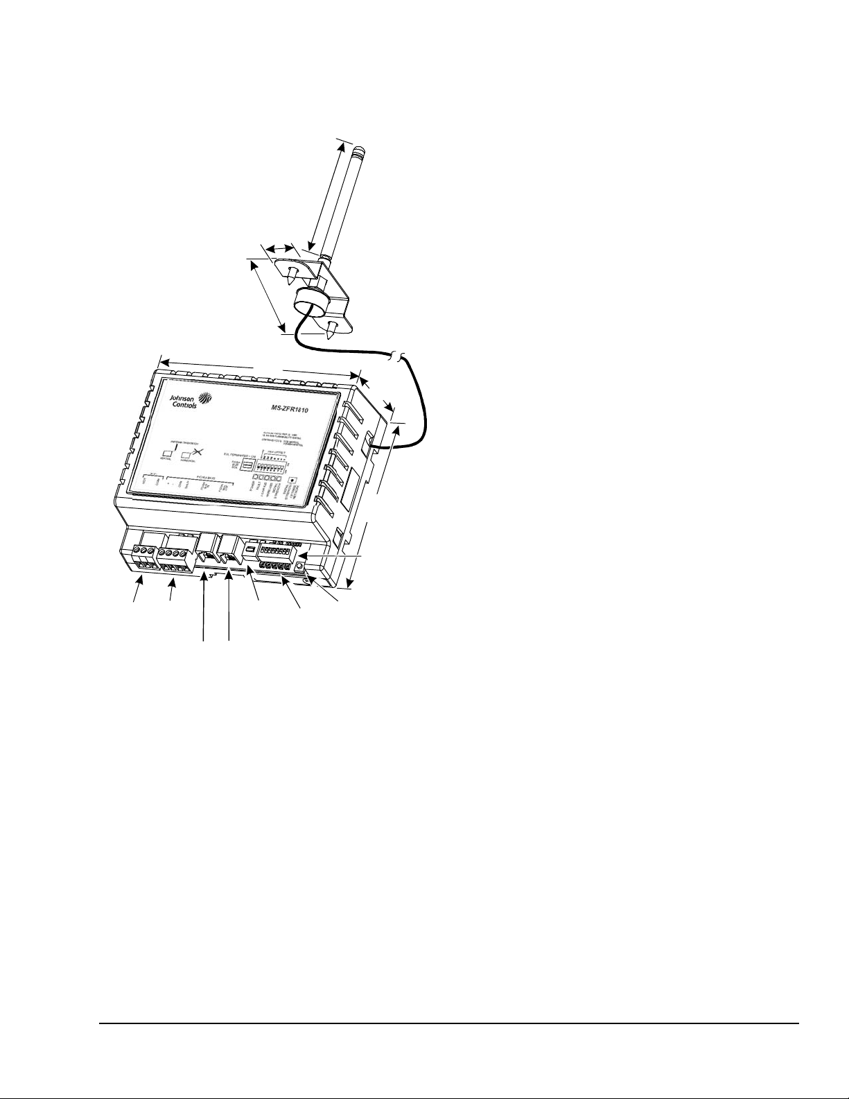
Dimensions
Figure 1: ZFR1810 Coordinator Physical
Features and Dimensions, mm (in.)
(4.8)
52
24 VAC
Input
Power
FC
BUS
Terminals
FC BUS
PWR OUT
Jack
FC BUS
PWR IN
Network
Button
LEDs
FIG:ZFR1810_ dimfeat
25
Switch
90
(50)
See Figure 1 for physical features and dimensions of
the ZFR1810 Coordinator.
(3.5)
• Due to the nature of the radio frequency waves, a
wireless device may have significantly different
signal strengths if its position changes relative to
another wireless device or if its environment
changes. If a ZFR1810 Coordinator shows poor
signal strength, you can improve the signal
strength by moving the device’s antenna a couple
of inches in either horizontal direction.
Termin al s
Jack
(1)
102
(4)
146
(5.8)
End-of-Line
Status
122
PAN OFFSET
DIP Switches
Optimize/Reform
(2.1)
1,270
• Locate the ZFR1810 Coordinator’s antenna in
line-of-sight with as many ZFR1811 Routers as
possible.
• Do not mount the ZFR1810 Coordinator’s antenna
in recessed areas, metal enclosures, or shelving
units.
Follow these additional guidelines when installing a
ZFR1810 Coordinator:
• Locate the ZFR1810 Coordinator near the center
of the associated array of ZFR1811 Routers.
• At a minimum, position a ZFR1810 Coordin at or
within 15.2 m (50 ft) of at least two
ZFR1811 Routers.
• At a minimum, position all ZFR1811 Routers within
15.2 m (50 ft) of at least two other ZFR1811
Routers or one ZFR1811 Router and the ZFR1810
Coordinator.
• Locate the ZFR1810 Coordinator on the same floor
as the associated ZFR1811 Router and
WRZ Series Sensors.
• Test the transmission signal strength between the
ZFR1810 Coordinator and the associated
ZFR1811 Router and WRZ Series Sensors to
ensure a reliable mesh network is in place. For
more information, see the ZFR1800 Series
Wireless Field Bus System Technical Bulletin
(LIT-12011295).
Mounting
Location Considerations
Follow these guidelines when locating a ZFR1810
Coordinator within a ZFR1800 Series system.
• Locate the ZFR1810 Coordinator so that it is easily
accessible.
• For best signal transmission, vertically orient the
ZFR1810 Coordinator’s antenna with at least
50 mm (2 in.) exposed below (and clear of) any
pipes, duct work, or other metal obstructions. Do
not mount the antenna in a horizontal orientation.
ZFR1810 Wireless Field Bus Coordinator Installation Instructions 3
• Avoid metal obstructions and concrete or brick
walls between the ZFR1810 Coordinator and the
associated ZFR1811 Router and WRZ Series
Sensors.
• Avoid configurations where a microwave oven is
located between two wireless devices. At a
minimum, ensure no microwave ovens are within
6 m (20 ft) of a ZFR1810 Coordinator.
Note: For detailed information on location guidelines
for a ZFR1800 Series system, and for estimating the
number of ZFR1811 Routers needed as repeaters for
extending wireless transmission range, refer to the
ZFR1800 Series Wireless Field Bus System Technical
Bulletin (LIT-12011295).
Page 4
Wireless Signal Transmission Considerations
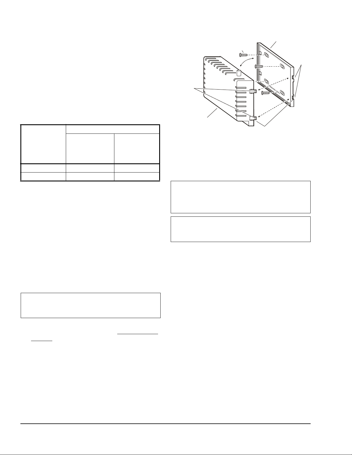
Figure 2: Mounting the ZFR1810 Coordinator
mount holes on mounting base and
tighten them evenly to the surface.
4. Reins t al l r eceiver
housing by alignin g l ocking
tabs with slots on mounting
base and pressing housing
until it locks on to base.
F
I
G
:
Z
F
R
1
8
1
0
_
m
n
t
_
b
s
e
Slots
Locking
Tabs (4)
Line-of-sight transmission ranges between a
ZFR1810 Coordinator, ZFR1811 Router, and/or a
WRZ Series Sensor can be less than the maximum
distances shown in Table 1. The effective transmission
range for indoor applications varies because of
wireless signal absorption and reflection due to metal
obstructions, walls (or floors), and furniture found in
typical building interiors. The effective transmission
range for outdoor applications varies based on
environmental conditions.
Table 1: Indoor Line-of-Sight Transmission
Ranges
Range Type Transmission Distance
ZFR1810
Coordinator,
ZFR1811
Router
Recommended 15.2 m (50 ft) 15.2 m (50 ft)
Maximum 76.2 m (250 ft) 30 m (100 ft)
Mounting the Base
The ZFR1810 Coordinator can be surface mounted
using the four No. 6 Trade Size self-tapping, pan-head
screws supplied.
To mount the ZFR1810 Coordinator base with screws:
1. Remove the ZFR1810 Coordinator from the
mounting base (Figure 2).
2. Use the mounting base as a template, and place
the mounting base against the mount i ng sur fa c e.
3. Drill pilot holes at the marked locations a nd se cu re
the mounting base to the surface with the four No.
6 Trade Size screws supplied.
IMPORTANT: Do not overtighten the mounting
screws. Overtightening the mounting screws may
damage the mounting base or mounting surface.
4. Mount the antenna and connect the antenna cable
to the ZFR1810 Coordinator. See Assembling the
Antenna.
5. Reinstall the ZFR1810 Coordinator housing to the
mounted base.
ZFR1810 Wireless Field Bus Coordinator Installation Instructions4
WRZ Series
Sensor
3. Insert the four No. 6 screws into
2. Use the mounting base
for screw hole template.
1. Remove receiver housing by
pressing th e l ocking tabs in at
the slots in the mounting base t o
release the receiver from base.
Assembling the Antenna
IMPORTANT: Use the antenna provided. Do not
alter the antenna in any way or use another
antenna. Do not modify the antenna cable in any
way.
IMPORTANT: Minimum bend radius for the
antenna cable is 25 mm (1 in.). Any bend with a
smaller radius may damage the cable.
If mounting the ZFR810 Coordinator in a control panel,
choose a location on the top side of the control panel
for placement of the antenna. Ensure that the selected
location has line-of-sight to two or more ZFR1811
Routers.
Use Figure 3 and the following steps to assemble the
remote-mount antenna:
1. Remove the knock-out tab on the enclosure/panel
box or drill a 7/8 in. diameter hole in the desired
location on the top of the enclosure.
2. Insert the round bushing into the hole in the
enclosure.
3. Insert the hexagonal bushing into the antenna
mounting bracket.
4. Thread the antenna cable through the hexagonal
bushing.
5. Insert the base of the antenna into the hexagonal
bushing and press until it snaps securely in place.
6. Thread the antenna cable through the round
bushing at the top of the panel.
Page 5

2. Remove the adhesive backing on two pieces of
Figure 3: Mounting the Antenna
Antenna
Antenna
Bracket
Hexagonal
Bushing
Round
Bushing
Screws
Antenna
Cable
Recloseable
Fastener Tape
t
n
m
_
t
n
a
_
0
1
8
1
R
F
Z
:
G
I
F
RFT and place one piece on the bottom of each
antenna bracket mounting foot.
3. Affix a mating piece of RFT onto each piece of RFT
on the mounting bracket so that the fasteners
mesh together. Remove the adhesive backing on
the mating pieces.
Mounting
Mounting
Mounting the Antenna Using Screws To mount the antenna using screws:
1. Center the antenna mounting bracket over the
7/8 in. (22 mm) round bushing.
2. Using the bracket as a template, drill two 3/32 in.
(2 mm) pilot holes into the enclosure.
3. Screw the bracket into place using the supplied
self-tapping mounting screws.
Mounting the Antenna Using Recloseable Fastener Tape (RFT)
When the unit is part of a panel assembly, the package
includes six pieces of RFT. Use this tape between the
antenna bracket and the enclosure. To mount the
antenna using RFT:
4. Center the bracket over the 7/8 in. (22 mm) round
bushing and apply the bracket to the top of the
panel. Push down on the feet of the bracket until
you feel the fasteners lock into position and the
adhesive bonding to the panel is completely
attached.
Note: Extra pieces of RFT are provided so that you
can change the mounting location on the top of the
panel at a later date if necessary.
Attaching the Antenna to the ZFR1810 Wireless Field Bus Coordinator
To attach the antenna to the ZFR1810 Coordinator:
1. Remove the top cover of the ZFR1810 Coordinator
by simultaneously pushing in both flexible tabs on
one side of the unit, followed by pushing in the tabs
on the other side of the unit.
2. Remove the top portion of the unit.
3. Apply the antenna wire firmly to the connection
point (see Figure 1) until it locks into place.
IMPORTANT: The connection from the antenna
cable to the ZFR1810 Coordinator is intended to be
made only once. Do not remove it once you have
inserted it into the jack. If you must remove the
antenna, disassemble the case of the Z FR 18 10
Coordinator and remove the antenna from the jack
by pulling on the knurled end of the antenna's
connector only. Pulling on the antenna cable from
anywhere else can result in damage to the antenna.
Avoid any repeat removals and re-insertions as this
may impact wireless connection integrity and unit
performance.
1. Ensure all mounting surfaces are clean and free of
dust, oils, and debris before applying the RFT.
ZFR1810 Wireless Field Bus Coordinator Installation Instructions 5
4. Replace the top portion and cover of the ZFR1810
Coordinator.
Page 6

Wiring
Figure 4: ZFR1810 Coordinator 24 VAC Power
Supply Connection
ZFR1810
Supply Power
Terminal Block
Plug
Wires from
Johnson C ontrols
24 VAC, Class 2
Power Transformer
(COM)
(24 VAC)
F
I
G
:
Z
F
R
1
8
1
0
_
P
w
r
_
P
r
t
24V~
C
O
M
H
O
T
Figure 5: ZFR1810 Coordinator Communication
Connection
FC/SA BUS
Terminal
Block
FC/SA BUS
Terminal Block
Plug
F
I
G
:
Z
F
R
1
8
1
0
_
F
C
_
S
A
_
B
s
S
H
L
D
A
C
O
M
-
Wiring Considerations and Guidelines
IMPORTANT: Do not connect supply power to the
ZFR1810 Coordinator before finishing wiring and
checking all wiring connections. Short circuits or
improperly connected wires may result in permanent
damage to the ZFR1810 Coordinator.
IMPORTANT: Use copper conductors only. Make
all wiring in accordance with local, national, and
regional regulations. The ZFR1810 Coordinator is a
low-voltage (less than 30 VAC) device. Do not
exceed the ZFR1810 Coordinator’s electrical
ratings.
IMPORTANT: Prevent any static electric discharge
to the ZFR1810 Coordinator. Static electric
discharge can damage the ZFR1810 Coordinator
and void any warranties.
IMPORTANT: Do not connect the ZFR1810
Coordinator to the power supply before setting the
PAN OFFSET switches.
M
O
C
ZFR1810
Supply Power
Terminal Block
Orange Wire
Brown W ir e
Terminal Blocks - Communication
Connect the communication wires from the NAE or
NCE to the four-position screw terminal pluggable
block, as shown in Figure 5 and Figure 1.
Follow these guidelines when wiring a
ZFR1810 Coordinator:
• Route the wires at least 50 mm (2 in.) away from
the vent slots on the sides of the
ZFR1810 Coordinator housing.
• Provide slack in the wires. Keep wires routed
neatly around the ZFR1810 Coordinator to
promote good ventilation, Light-Emitting Diode
(LED) visibility, and ease of service.
Power Input and Communication
Wiring for power input and communication uses one of
two methods: terminal blocks or the FC Bus jack.
Terminal Blocks - Power
Use a 24 VAC nominal, 50/60 Hz, Class 2 power
supply to power the ZFR1810 Coordinator . See Table 4
for recommended Johnson Controls® transformers.
Connect the 24 VAC supply power wires from the
transformer to the HOT and COM terminals of the
24 V~ three-position screw terminal pluggable block as
shown in Figure 4 and Figure 1. The middle terminal is
not used.
Note: Transformers not manufactured by
Johnson Controls may have different color wires.
Follow the manufacturer’s instructions when mounting
and wiring transformers.
ZFR1810 Wireless Field Bus Coordinator Installation Instructions6
D
M
L
O
H
S
A
C
(MS/TP)
FC/SA Bus
-
+
+
= + - COM
FC Bus Jack - Power and Communication
Use a six conductor SA Bus RS-485 cable with
RJ12 connectors to connect the ZFR1810 Coordinator
to the FC Bus connector (FC/SA BUS IN) on the NAE
or NCE supervisory engine. This connection provides
both power and communication to the ZFR1810
Coordinator.
Page 7

Power Supply Output
Figure 6: Setting the DIP Switches
IMPORTANT: Do not exceed the power supply
output of the ZFR1810 Coordinator. The ZFR1810
Coordinator’s power supply input must be able to
source the ZFR1810 Coordinator and the connected
external devices. Exceeding the power supply input
limits may cause the ZFR1810 Coordinator to shut
down.
Use a six-conductor SA Bus RS-485 cable with
RJ45 connectors to connect an external Metasys®
device to the FC BUS OUT jack as shown in Figure 1.
Setup and Adjustments
PAN Offset
IMPORTANT: Ensure that the PAN Offset switches
are set to the same value for the
ZFR1810 Coordinator and each associated
ZFR181 1 Router , and WRZ Series Sensor in a mesh
network.
IMPORTANT: To avoid MS/TP address conflicts,
do not connect the ZFR1810 Coordinator to the
power supply before setting the PAN Offset
switches.
PAN Offset and MS/TP Address Interaction
At Release 4.1 and later, the MS/TP address of the
ZFR1810 Coordinator is no longer fixed at 2. The new
address is 120 plus the sum of the first three va lues
of the P AN Offse t that are set to the ON position, giving
an MS/TP address range of 120 to 127.
Set the PAN Offset value of the ZFR1810 Coordinator
using the Dual Inline Package (DIP) switches to
configure the ZFR1810 Coordinator to communicate
with the ZFR1811 Routers assigned to it. See Figure 1
and Figure 6.
The PAN Offset value equals the sum of the numbe r s
set to ON. For example, if the DIP switches labelled
1, 4, and 8 are set to ON, the PAN Offset value is 13
(1 + 4 + 8 = 13).
When selecting a PAN Offset value for a wireless
system:
• Use a unique PAN Offset value for each wireless
mesh network at a job site.
• Use the same PAN Offset value for each wireless
device in a wireless mesh network - the
ZFR1810 Coordinator and each associated
ZFR1811 Router and WRZ Series Sensor.
ZFR1810 Wireless Field Bus Coordinator Installation Instructions 7
Page 8

Note: Only the values associated with the first three
Figure 7: EOL Switch
1
O
N
ON Position
OFF Position
F
I
G
:
E
O
L
_
s
w
t
c
h
switches (right to left) set to the ON position count
towards the MS/TP address of the ZFR1810
Coordinator. See the top of Figure 6.
Refer to the ZFR1800 Series Wireless Field Bus
System Technical Bulletin (LIT-12011295) for more
information on determining the signal strength between
ZFR1800 Series devices in your application.
Note: On some date code labels, the switch position
numbers on the bottom of the dip switch are reversed.
In either case, the switch positions are always read
right to left.
In Figure 6, the PAN Offset of the ZFR1810
Coordinator is configured by adding the values
associated with the first seven switch positions (right to
left). The eighth switch position is no t used. In Figu re 6
the PAN Offset is configured to 13 (values 1, 4, and 8)
to the ON position. In Figure 6, the MS/TP address of
the ZFR1810 Coordinator is configured by adding the
values associated with the first three switch positions
(right to left).The sum of the values is 5, so the MS/TP
address of the ZFR1810 Coordinator is 120 + 5, which
equals 125.
Setting the FC Bus End-of-Line (EOL) Switch
The FC Bus End-of-Line termination switch allows you
to designate the ZFR1810 Coordinator as the end of
the FC Bus. The default position is OFF. If the
ZFR1810 Coordinator is at the end of a daisy chain of
devices on the FC Bus, set the EOL switch to the ON
position. See Figure 1 and Figure 7.
O
1
N
WRZ-SST-120 Wireless Sensing System Tool
Use the WRZ-SST-120 Wireless Sensing System Tool
with a WRZ Series Sensor as a site survey tool to
determine the wireless signal strength between a
ZFR1810 Coordinator and a ZFR1811 Router or
between two ZFR1811 Routers. Refer to the
WRZ-SST-120 Wireless Sensing System Tool
Installation Instructions (Part No. 24-10563-12) for
more information on testing signal strength in your
application.
Network Optimize/Reform Button
The Network Optimize/Reform Button allows the
ZFR1810 Coordinator to use any of three functions:
• Signal Strength
• Network Optimize
• Network Reform
Use the Signal Str ength mode to aid in signal strength
testing. Signal Strength mode causes the LEDs on the
ZFR1811 routers to turn on and display signal strength
for two hours.
Use the Network Optimize mode to clear the mesh
device routing tables of the ZFR1811 Routers and
attempt to find shorter and/or stronger signal paths to
the ZFR1810 Coordinator.
Troubleshooting
Wireless Signal Strength
A wireless signal strength indication LED displays the
reception strength of the transmissions between the
ZFR1810 Coordinators, ZFR1811 Routers, and the
WRZ Series Sensors. This LED helps determine the
network connectivity status when selecting locations for
the devices during system installation.
Approximately once every 10 seconds, the Signal
Strength LED flashes to indicate the reception strength
of the signal from neighboring devices. See Table 3
and Figure 1.
Note: The Network Optimize process can take up to
15 minutes to complete.
Refer to the ZFR1800 Series Wireless Field Bus
System Technical Bulletin (LIT-12011295) for more
information about the Network Reform function.
Table 2: Network Optimize/Reform Button
Holding the Network
Optimize/Reform Button
for ___
0–5 Seconds Signal Strength
1
5–10
More than 10
1. Once the Signal Strength LED begins blinking rapidly,
release the button (between 5 to 10 seconds).
2. Once the Signal Strength LED stops blinking rapidly and
stays ON, release the button (approximately
10 seconds).
2
Puts the ZFR1810
Coordinator into the
_____ Mode
Network Optimize
Network Reform
ZFR1810 Wireless Field Bus Coordinator Installation Instructions8
Page 9

Troubleshooting LEDs
The ZFR1810 Coordinator has five LEDs that indicate
power, fault status, FC Bus activity, wireless activity,
and signal strength. See Figure 1. These status LEDs
are described in Table 3.
Table 3: ZFR1810 Coordinator Status LEDs
Name Color Normal Descriptions
Power Green On Off Steady = No power.
On Steady = Normal operation (power available
from 24 VAC connector or Field Controller
Sensor Actuator [FC/SA] Bus IN jack).
Fault Red Off Off Steady = Normal.
On Steady = Internal Errors detected.
FC Bus Green Blink Blink - 2 Hz = Normal operation (ZFR1810
Wireless Green Blink Blink - 2 Hz = Normal operation (ZFR1810
Signal Strength Green
Signal Strength
3 Flashes - Excellent
2 Flashes - Good
1 Flash - Weak
OFF for 3 seconds - None
1
Indication:
Coordinator is receiving BACnet® frames over the
wire).
Off Steady = Attempting to Auto Baud, or not
connected to active MS/TP network.
On Steady = Auto Baud complete and not
receiving BACnet frames.
Coordinator is receiving BACnet frames over the
wire).
Off Steady = Not receiving BACnet frames.
On Steady = Stopped receiving BACnet frames.
OFF Steady = Not able to start a network.
ON Steady with Signal Strength displayed once
every 10 seconds = Normal operation (ZFR1810
Coordinator is a member of a wireless network).
1. Signal Strength appears once every 10 seconds or when the Network Optimize/Reform button on the
ZFR1810 Coordinator is depressed momentarily (less than 5 seconds).
Repair Information
If the ZFR1810 Wireless Field Bus Coordinator fails to
operate within its specifications, replace the unit. For a
Note: The firmware in the ZFR1810 Coordinator can
be upgraded using the Controller Configuration Tool
(CCT).
replacement ZFR1810 Coordinator , contact the nearest
Johnson Controls representative.
ZFR1810 Wireless Field Bus Coordinator Installation Instructions 9
Page 10

Accessories
Table 4: Accessories (Order Separately)
Product Code
Product Description
Number
TP-2420 Transformer, Wall Plug Mount, 120 VAC to 24 VAC, 20 VA, Class 2
WRZ-SST-120 Wireless Sensing System Tool. Requires WRZ Series Sensor to function as a site survey tool for
ZFR1800 Wireless Field Bus System, or for WRZ-7860-0 One-to-One Room Sensing System.
Y65T31-0
ZFR-USBHA-0 USB Dongle with ZFR Driver provides a wireless connection through the CCT to allow wireless
ZFR-1810ANT-700 Replacement antenna kit for ZFR1810 Wireless Field Bus Coordinator. Includes antenna, coaxial
1. Additional Y60 Series Transformers are available from Johnson Controls.
1
Transformer, 120/2 08/240 VAC to 24 VAC, 40 VA, Class 2, Foot Mount, 20 cm (8 in.) Primary Leads
and Secondary Screw Terminals
commissioning of the wireless enabled FAC, FEC, IOM, and VMA16 controllers. The USB ZFR Dongle
is also used with the ZFR Checkout Tool used to troubleshoot and validate ZFR wireless meshes using
a laptop computer.
cable, and mounting hardware.
Technical Specifications
ZFR1810 Wireless Field Bus Coordinator (Part 1 of 2)
Product Code Number MS-ZFR1810-x
Power Supply Input One of the following:
• 24 VAC +10%/-15%, 50/60 Hz, Class 2. Transformer allowance should be 2.5 VA
maximum, 2 VA typical. Provided through the three-position 24 V~ screw terminal
pluggable block.
• 15 VDC, 180 mA (7 to 18 VDC, 185 mA maximum current draw) on the FC Bus
provided through the FC/SA BUS IN RJ-12 jack from the FC Bus Jack on a Field
Controller or NxE supervisory engine.
Power Supply Output 15 VDC; Provided through the FC/SA BUS, FC/SA BUS OUT RJ-12 jack for external
devices.
Addressing DIP Switches, Field Adjustable
Wireless Band Direct-Sequence Spread-Spectrum, 2.4 GHz ISM Bands
Transmission Power 10 mW Maximum
Transmission Range 76.2 m (250 ft) Maximum Line-of-Sight
15 m (50 ft) Recommended
Ambient Conditions Operating: 0 to 50°C (32 to 122°F), 5 to 95% RH, Noncondensing
Storage: -20 to 70°C (-4 to 158°F), 5 to 90% RH, Noncondensing
Materials White Plastic Housing with Plenum rating per UL1995 UL94-5VB Fl ammability Rating
Terminations Two spade terminals with three-position screw terminal pluggable block for 24 VAC power
Dimensions 146 x 122 x 52 mm (5.8 x 4.8 x 2.1 in.)
supply input.
Four spade terminals with four-position screw terminal pluggable block for RS-485
communications.
RJ-12 IN jack for 15 VDC power supply and communications connection from an NxE or
FEC FC Bus jack.
RJ-12 OUT jack supplies 15 VDC and communications to BTCVT Wireless
Commissioning Converter.
ZFR1810 Wireless Field Bus Coordinator Installation Instructions10
Page 11

Metasys® and Johnson Controls® are registered trademarks of Johnson Controls, Inc.
All other marks herein are the marks of their respective owners. © 2016 Johnson Controls, Inc.
Building Efficiency
507 E. Michigan Street, Milwaukee, WI 53202
ZFR1810 Wireless Field Bus Coordinator (Part 2 of 2)
Mounting Hardware Four No. 6 Trade Size Sheet Metal Screws
Shipping Weights 0.45 kg (1.0 lb)
Compliance United States:
Intended for Connection to an NEC Class 2 Power Source;
UL 916 Energy Management
Plenum rated per UL1995 UL94-5VB Flammability Rating
FCC Compliant to CFR47, Part 15, Subpart B, Class A
Transmission Complies with FCC Part 15.247 Regulations for Low Power Unlicensed
Transmitters
Transmitter Identification ZFR1810-0: FCC: TFB-MATRIXL
Transmitter Identification ZFR1810-1: FCC: OEJ-WRZRADIO
Canada:
CAN/CSA C22.2 No. 205, Signal Equipment
Industry Canada (IC) Compliant to Canadian ICES-003, Class B Limits
Industry Canada (IC) RSS-210
Transmitter Identification ZF R1810-0: 5969A-MATRIXLP
Transmitter Identification ZFR1810-1: 279A-WRZRADIO
Australia and New Zealand: RCM Mark, Australia/NZ Emissions Compliant
Europe:
CE Mark – Johnson Controls, Inc., declares that this product is in compliance with the
essential requirements and other relevant provisions of the EMC Directive.
The performance specifications are nominal and conform to acceptable industry standard. For application at conditions beyond these
specifications, consult the local Johnson Controls office. Johnson Controls, Inc. shall not be liable for damages resulting from misapplication or
misuse of its products.
European Single Point of Contact: NA/SA Single Point of Contact: APAC Single Point of Contact:
JOHNSON CONTROLS
WESTENDHOF 3
45143 ESSEN
GERMANY
JOHNSON CONTROLS
507 E MICHIGAN ST
MILWAUKEE WI 53202
USA
JOHNSON CONTROLS
C/O CONTROLS PRODUCT MANAGEMENT
NO. 22 BLOCK D NEW DISTRICT
WUXI JIANGSU PROVINCE 214142
CHINA
ZFR1810 Wireless Field Bus Coordinator Installation Instructions 11
Published in U.S.A. www.johnsoncontrols.com
 Loading...