

Page 1
SINGLE PIECE
INSTALLATION MANUAL
ISO 9001
Certified Quality
Management System
VARIABLE SPEED AIR HANDLERS
MODELS: AV*(C) SERIES
LIST OF SECTIONS
GENERAL . . . . . . . . . . . . . . . . . . . . . . . . . . . . . . . . . . . . . . . . . . . . . .1
SAFETY . . . . . . . . . . . . . . . . . . . . . . . . . . . . . . . . . . . . . . . . . . . . . . . .1
UNIT INSTALLATION . . . . . . . . . . . . . . . . . . . . . . . . . . . . . . . . . . . . .2
ELECTRIC HEATER INSTALLATION . . . . . . . . . . . . . . . . . . . . . . . .7
LOW VOLTAGE CONTROL CONNECTIONS . . . . . . . . . . . . . . . . . .7
REQUIRED CONTROL SET-UP . . . . . . . . . . . . . . . . . . . . . . . . . . . .10
LIST OF FIGURES
Typical Installation . . . . . . . . . . . . . . . . . . . . . . . . . . . . . . . . . . . . . . . .3
Return Duct Attachment & Component Location . . . . . . . . . . . . . . . . .3
Dimensions & Duct Connection Dimensions . . . . . . . . . . . . . . . . . . . .4
Condensate Deflector on Vertical Drain Pan . . . . . . . . . . . . . . . . . . . .4
Condensate Deflecctor on Horizontal Drain Pan Edge . . . . . . . . . . . .5
S-Clip Installation . . . . . . . . . . . . . . . . . . . . . . . . . . . . . . . . . . . . . . . . .5
Duck Work Transition . . . . . . . . . . . . . . . . . . . . . . . . . . . . . . . . . . . . . .5
Typical Horizontal Installation . . . . . . . . . . . . . . . . . . . . . . . . . . . . . . .6
LIST OF TABLES
Dimensions . . . . . . . . . . . . . . . . . . . . . . . . . . . . . . . . . . . . . . . . . . . . . . . . . 4
Low Voltage Connections . . . . . . . . . . . . . . . . . . . . . . . . . . . . . . . . . . . . . . 8
Low Voltage Connections . . . . . . . . . . . . . . . . . . . . . . . . . . . . . . . . . . . . . 10
Fault Codes . . . . . . . . . . . . . . . . . . . . . . . . . . . . . . . . . . . . . . . . . . . . . . . 10
Heat Relays . . . . . . . . . . . . . . . . . . . . . . . . . . . . . . . . . . . . . . . . . . . . . . . 11
Comfort Setting Selection . . . . . . . . . . . . . . . . . . . . . . . . . . . . . . . . . . . . . 12
Physical and Electrical Data - Cooling Only (60 Hz) . . . . . . . . . . . . . . . . 12
Electrical Data - Cooling Only (60 Hz) . . . . . . . . . . . . . . . . . . . . . . . . . . . 13
Conversion Table . . . . . . . . . . . . . . . . . . . . . . . . . . . . . . . . . . . . . . . . . . . 13
Electrical Data - 208/230-1-60 . . . . . . . . . . . . . . . . . . . . . . . . . . . . . . . . . 13
LINE POWER CONNECTIONS . . . . . . . . . . . . . . . . . . . . . . . . . . . . 11
AIRFLOW AND COMFORT SETTING SELECTION . . . . . . . . . . . . 12
UNIT DATA . . . . . . . . . . . . . . . . . . . . . . . . . . . . . . . . . . . . . . . . . . . 12
MAINTENANCE . . . . . . . . . . . . . . . . . . . . . . . . . . . . . . . . . . . . . . . . 17
WIRING DIAGRAM . . . . . . . . . . . . . . . . . . . . . . . . . . . . . . . . . . . . . 18
TXV . . . . . . . . . . . . . . . . . . . . . . . . . . . . . . . . . . . . . . . . . . . . . . . . . . . 6
Proper Bulb Location . . . . . . . . . . . . . . . . . . . . . . . . . . . . . . . . . . . . . 6
Air Handler Control Board – Communications Connections . . . . . . . . 7
Cooling Models with and without Electric Heat Wiring . . . . . . . . . . . . 8
Two-Stage Heat Pump Wiring . . . . . . . . . . . . . . . . . . . . . . . . . . . . . . 9
Air Handler with Communicating AC or HP . . . . . . . . . . . . . . . . . . . . 9
Line Power Connections . . . . . . . . . . . . . . . . . . . . . . . . . . . . . . . . . . 11
Wiring Diagram . . . . . . . . . . . . . . . . . . . . . . . . . . . . . . . . . . . . . . . . . 18
Electrical Data - (For Single Source Power Supply) -
Copper Wire - 208/230-1-60 . . . . . . . . . . . . . . . . . . . . . . . . . . . . . . . . . . . 14
Electrical Data - (For Multi-Source Power Supply) -
Copper Wire - 208/230-1-60 . . . . . . . . . . . . . . . . . . . . . . . . . . . . . . . . . . . 14
Electrical Data - 208/230-3-60 . . . . . . . . . . . . . . . . . . . . . . . . . . . . . . . . . 15
Electrical Data - (For Single Source Power Supply) -
Copper Wire - 208/230-3-60 . . . . . . . . . . . . . . . . . . . . . . . . . . . . . . . . . . 15
Electrical Data - (For Multi-Source Power Supply) -
Copper Wire - 208/230-3-60 . . . . . . . . . . . . . . . . . . . . . . . . . . . . . . . . . . . 15
Air Handler Air Flow Data . . . . . . . . . . . . . . . . . . . . . . . . . . . . . . . . . . . . . 16
SECTION I: GENERAL
The AV single piece air handler provides the flexibility for installation in
any upflow, downflow, or horizontal application.
These versatile models may be used for cooling or heat pump operation
with or without electric heat.
A BRAND LABEL (available from Distribution) may be applied to the
center of the blower access panel on AVG models.
The unit can be positioned for bottom return air in the upflow position,
top return air in the downflow position, and right or left return in the horizontal position.
Top and side power wiring and control wiring, accessible screw terminals for control wiring, easy to install drain connections and electric
heaters all combine to make the installation easy, and minimize installation cost.
SECTION II: SAFETY
This is a safety alert symbol. When you see this symbol on
labels or in manuals, be alert to the potential for personal
injury.
Understand and pay particular attention to the signal words DANGER,
WARNING, or CAUTION.
DANGER indicates an imminently hazardous situation, which, if not
avoided, will result in death or serious injury
WARNING indicates a potentially hazardous situation, which, if not
avoided, could result in death or serious injury
.
.
CAUTION indicates a potentially hazardous situation, which, if not
avoided may result in minor or moderate injury.
alert against unsafe practices and hazards involving only property damage.
Improper installation may create a condition where the operation of
the product could cause personal injury or property damage.
Improper installation, adjustment, alteration, service or maintenance
can cause injury or property damage. Refer to this manual for assistance or for additional information, consult a qualified contractor,
installer or service agency.
This product must be installed in strict compliance with the installation
instructions and any applicable local, state, and national codes
including, but not limited to building, electrical, and mechanical codes.
FIRE OR ELECTRICAL HAZARD
Failure to follow the safety warnings exactly could result in serious
injury, death or property damage.
A fire or electrical hazard may result causing property damage, personal injury or loss of life.
It is also used to
536636-UIM-D-1211
Page 2
536636-UIM-D-1211
NOTICE
1. Install this air handler only in a location and position as specified in
SECTION III of these instructions.
2. Always install the air handler to operate within the air handler’s
intended maximum outlet air temperature. Only connect the air
handler to a duct system which has an external static pressure
within the allowable range, as specified on the air handler rating
plate.
3. When an air handler is installed so that supply ducts carry air circulated by the air handler to areas outside the space containing
the air handler, the return air shall also be handled by duct(s)
sealed to the air handler casing and terminating in the space to be
cooled/heated.
4. The air handler is not to be used for temporary heating of buildings
or structures under construction.
5. The size of the unit should be based on an acceptable heat loss or
gain calculation for the structure. ACCA, Manual J or other
approved methods may be used.
SAFETY REQUIREMENTS
1. This air handler should be installed in accordance with all national
and local building/safety codes and requirements, local plumbing
or wastewater codes, and other applicable codes.
2. Refer to the unit rating plate for the air handler model number, and
then see the dimensions page of this instruction for supply air plenum dimensions in Figure 3. The plenum must be installed according to the instructions.
3. Provide clearances from combustible materials as listed under
Clearances to Combustibles.
4. Provide clearances for servicing ensuring that service access is
allowed for electric heaters and blower.
5. Failure to carefully read and follow all instructions in this manual
can result in air handler malfunction, death, personal injury and/or
property damage.
6. Check the rating plate and power supply to be sure that the electrical characteristics match.
7. Air handler shall be installed so the electrical components are protected from water.
8. Installing and servicing heating/cooling equipment can be hazardous due to the electrical components. Only trained and qualified
personnel should install, repair, or service heating/cooling equipment. Untrained service personnel can perform basic maintenance
functions such as cleaning and replacing the air filters. When
working on heating/cooling equipment, observe precautions in the
manuals and on the labels attached to the unit and other safety
precautions that may apply.
9. These instructions cover minimum requirements and conform to
existing national standards and safety codes. In some instances
these instructions exceed certain local codes and ordinances,
especially those who have not kept up with changing residential
and non-HUD modular home construction practices. These
instructions are required as a minimum for a safe installation.
INSPECTION
As soon as a unit is received, it should be inspected for possible damage during transit. If damage is evident, the extent of the damage
should be noted on the carrier’s freight bill. A separate request for
inspection by the carrier’s agent should be made in writing. Also, before
installation the unit should be checked for screws or bolts, which may
have loosened in transit. There are no shipping or spacer brackets
which need to be removed.
Also check to be sure all accessories such as heater kits, suspension
kits, and coils are available. Installation of these accessories or field
conversion of the unit should be accomplished before setting the unit in
place or connecting any wiring, electric heat, ducts or piping.
LIMITATIONS
These units must be wired and installed in accordance with all national
and local safety codes.
Voltage limits are as follows:
1
Air Handler Voltage Voltage code
208/230-1-60 06 187-253
1. Rated in accordance with ARI Standard 110, utilization range “A”.
Airflow must be within the minimum and maximum limits approved for
electric heat, evaporator coils and outdoor units.
Entering Air Temperature Limits
Wet Bulb Temp.°F Dry Bulb Temp. °F
Min. Max. Min. Max.
57 72 65 95
Normal Operating
Voltage Range
SECTION III: UNIT INSTALLATION
CLEARANCES
Clearances must be taken into consideration, and provided for as follows:
1. Refrigerant piping and connections - minimum 12” recommended.
2. Maintenance and servicing access - minimum 36” from front of unit
recommended for blower motor/coil replacement.
3. Condensate drain lines routed to clear filter and panel access.
4. Filter removal - minimum 36” recommended.
5. The ductwork and plenum connected to this unit are designed for
zero clearance to combustible materials.
6. A combustible floor base accessory is available for downflow
applications of this unit, if required by local code.
LOCATION
Location is usually predetermined. Check with owner’s or dealer’s
installation plans. If location has not been decided, consider the following in choosing a suitable location:
1. Select a location with adequate structural support, space for service access, clearance for air return and supply duct connections.
2. Use hanging brackets to wall mount this single piece air handler
unit, is not recommended.
3. Normal operating sound levels may be objectionable if the air handler is placed directly over some rooms such as bedrooms, study,
etc.
4. Select a location that will permit installation of condensate line to
an open drain or outdoors allowing condensate to drain away from
structure.
The primary and secondary drain line must be trapped to allow proper
drainage of condensate water. If the secondary drain line is not used,
it must be capped. The coil is provided with a secondary drain. It
should be piped to a location that will give the occupant a visual warning that the primary drain is clogged. If the secondary drain is not
used it must be capped.
5. Proper electrical supply must be available.
6. If unit is located in an area of high humidity (ie: an unconditioned
garage or attic), nuisance sweating of casing may occur. On these
installations, unit duct connections and other openings should be
properly sealed and a wrap of 2” fiberglass insulation with vinyl
vapor barrier should be used.
2 Johnson Controls Unitary Products
Page 3
536636-UIM-D-1211
NOTICE
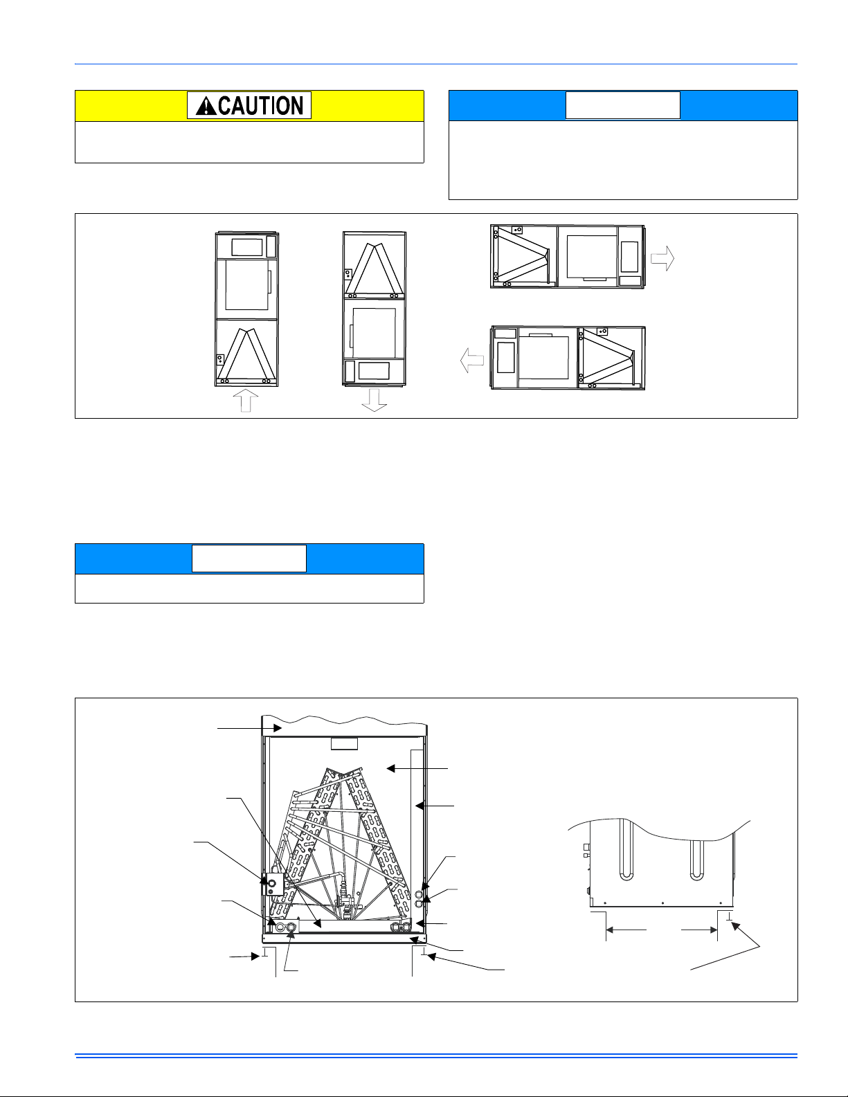
UPFLOW DOWNFLOW
HORIZONTAL RIGHT
HORIZONTAL LEFT
NOTICE
FRONT VIEW
SIDE VIEW
BLOWER
COMPARTMENT
VERTICAL
DRAIN PAN
REFRIGERANT LINE
CONNECTIONS
PRIMARY DRAIN
UPFLOW 3/4”
THREADED
DUCT WORK MAY
BE FASTENED
CAUTIOUSLY WITH
SCREWS TO THE
SIDES AND REAR OF UNIT
SECONDARY DRAIN
UPFLOW 3/4” THREADED
COIL COMPARTMENT
(Access panel removed)
HORIZONTAL
DRAIN PAN
HORIZONTAL
SECONDARY DRAIN
HORIZONTAL
PRIMARY DRAIN
ALTERNATE
DRAIN CONNECTIONS
UPFLOW/DOWNFLOW
FILTER DOOR
RETURN AIR
DUCT
WHEN ATTACHING DUCT WORK WITH
SCREWS - KEEP SCREWS WITHIN 5/8”
OF SIDES AND BACK OF AIR HANDLER
When an evaporator coil is installed in an attic or above a finished
ceiling, an auxiliary drain pan should be provided under the coil as is
specified by most local building codes.
FIGURE 1: Typical Installation
DOWNFLOW AND HORIZONTAL CONVERSION
(AV ONLY)
These air handler units are supplied ready to be installed in a upflow
and right hand horizontal position. If unit requires left hand positioning,
the unit must have the coil assembly repositioned.
1. Remove blower, coil, and filter access panels.
Conversion must be made before brazing the refrigerant connections
to the coil.
For downflow and horizontal left installations, follow steps 2 - 8.
2. Remove tubing connection panel.
3. Remove front drain pan, hold down bracket.
4. Slide coil assembly out of air handler.
5. Rotate cabinet 180º so blower outlet is facing down.
In severe high humidity, high temperature indoor unit environments,
an accessory insulation blanket is available to supplement the standard cabinet insulation. Insulate with UPG Kit: 1VJ0117 for B cabinets, 1VJ0121 for C cabinets or 1VJ0124 on D cabinets or seal
completely with adequate fiberglass insulation using vapor barrier on
the outside.
6. Re-install coil assembly on downflow bracket.
7. Re-attach front drain pan, hold down bracket.
8. Re-attach tubing connection panel.
9. For horizontal applications, rotate air handler 90º into desired ori-
entation.
10. Re-position drain plugs as necessary based on air handler orienta-
tion.
11. Re-position and replace access panels.
12. For downflow installations, the cladding should be reconfigured so
that the grille and circuit breaker covers having logos and/or black
coloring are at the top of the unit on the coil access panel. See
below.
13. Apply branding label to air handler in recessed area provided on
blower access panel cladding. This label should be applied after
the air handler is placed in its proper orientation so the label is
right side up.
FIGURE 2: Return Duct Attachment & Component Location
Johnson Controls Unitary Products 3
Page 4
536636-UIM-D-1211
NOTICE
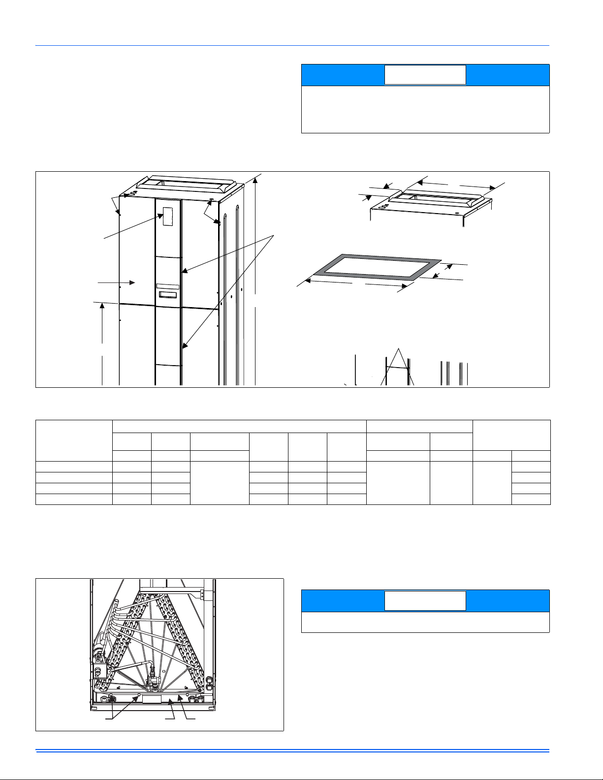
10-3/8”
F
CIRCUIT
BREAKER
PANEL
BOTTOM INLET
DIMENSIONS
BLOWER
COMPARTMENT
REFRIGERANT
DRAIN CONNECTIONS
FOR UPFLOW AND
DOWNFLOW APPLICATIONS
D
A
E
TOP OUTLET
DIMENSIONS
18-9/32”
J
K
CLADDING
CONDENSATE
S-CLIPS (3)
VERTICAL
NOTICE
CLADDING CONFIGURATION FOR DOWNFLOW
INSTALLATION (IF USED)
To reconfigure the cladding parts, remove the grille by pulling gently at
the top. Once the grille is removed, the circuit breaker cover can also be
removed. Remove the gray, non-branded grille and circuit breaker
cover from the cladding on the coil access panel. Next, remove the
black and/or branded grille and circuit breaker cover from the blower
access panel. Install these pieces into the coil access panel cladding so
they are at the top of the air handler. Install the gray, non-branded grille
and circuit breaker cover in the blower access panel cladding.
If a heat kit with a circuit breaker is installed in the air handler, the circuit breaker cover cladding must be removed to gain access to the
sheet metal cover plate. Some local codes may require that the circuit
breaker remain visible. If so, do not re-install circuit breaker cover
cladding.
FIGURE 3: Dimensions & Duct Connection Dimensions
TABLE 1:
Dimensions
Dimensions (Inches)
Models
AV
AB C
Height Width Depth Power Control Liquid Vapor
24B 46 17 1/2
36C 52 21 17-1/8 17-13/32 18-3/32 7/8”
48D 57 24 1/2 22-1/8 20-29/32 21-19/32 7/8”
60D 57 24 1/2 22-1/8 20-29/32 21-19/32 7/8’
1. Actual size (Conduit size).
21-1/2
(w/o cladding)
22-1/2
(with cladding)
SUCTION FEEDER TUBE CONDENSATE
DEFLECTOR
UPFLOW OR DOWNFLOW
No action required. See Figure 4.
DEF
12-3/8 13-29/32 14-19/32
Horizontal Left or Right
Use an appropriate tool to pry out water deflector with two or three sclips from the vertical drain pan. See Figure 4. Relocate the deflector
with s-clips on the Horizontal Drain Pan lined up to the coil support
brackete. See Figure 5. This positions the deflector below the feeder
tubes to channel the condensate to the drain pan.
The condensate deflector should be installed in the s-clip section
which is inside the drain pan edge. See Figure 6.
Wiring Knockouts
JK
7/8” (1/2”)
1 3/8” (1”)
7/8” (1/2”) 3/8”
1 23/32” (1 1/4”)
1
Refrigerant
Connections
Line Size
3/4”
FIGURE 4: Condensate Deflector on Vertical Drain Pan
4 Johnson Controls Unitary Products
Page 5
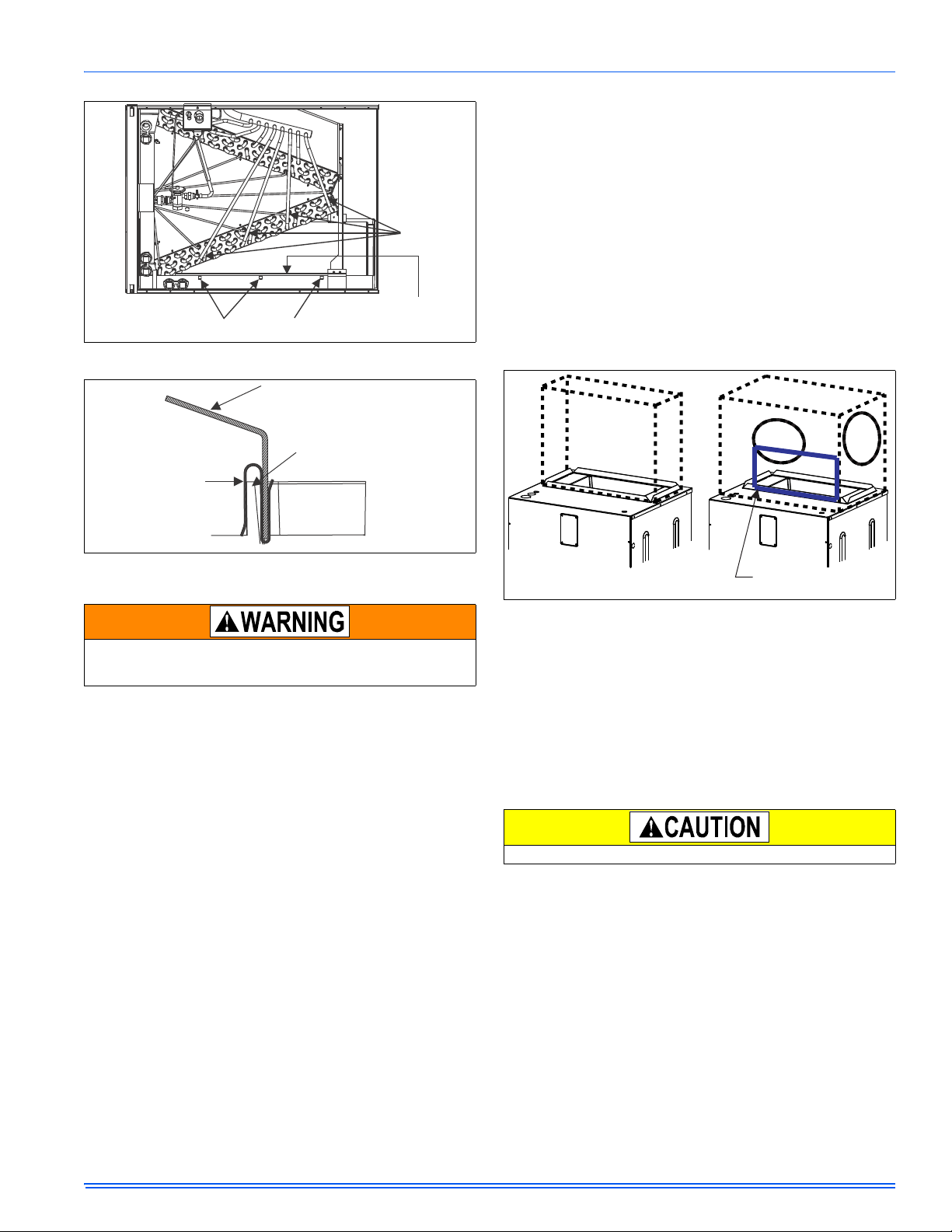
FIGURE 5: Condensate Deflecctor on Horizontal Drain Pan Edge
S-CLIPS ON HORIZONTAL PAN
FEEDER
TUBES
CONDENSATE
DEFLECTOR
DEFLECTOR
S-CLIP
DRAIN PAN
WALL
SUGGESTED LOCATION
OF BLOCK OFF PLATE
RECOMMENDED
TRANSITION
536636-UIM-D-1211
ers and never fastened directly to the structure. This unit is not
designed for non-ducted (freeblow) applications. Size outlet plenum or
transition to discharge opening sizes shown in Figure 3.
Duct work should be fabricated and installed in accordance with local
and/or national codes. This includes the standards of the National Fire
Protection Association for Installation of Air-Conditioning and Ventilating Systems, NFPA No. 90B.
DUCT WORK TRANSITION
Duct work that is not designed to match the supply air opening can
cause turbulence inside the plenum box. This turbulence can change
the air flow patterns across the heat kit limit switch. If the factory suggested transition can not be fabricated, it is recommended a block off
plate (approximately 8” in height and running the full width of the plenum) be attached to the supply opening Please refer to Figure 7 as a
visual aid. The use of this block off plate will keep better air circulation
across the limit switch.
FIGURE 6: S-Clip Installation
DUCT CONNECTIONS
Use 1/2" screws to connect ductwork to bottom of unit. Longer screws
will pierce the drain pan and cause leakage. If pilot holes are drilled,
drill only though field duct and unit bottom flange.
Air supply and return may be handled in one of several ways best
suited to the installation. See Figure 3 for dimensions for duct inlet and
outlet connections.
The vast majority of problems encountered with combin ation heating
and cooling systems can be linked to improperly designed or installed
duct systems. It is therefore highly important to the success of an installation that the duct system be properly designed and installed.
Use flexible duct collars to minimize the transmission of vibration/noise
into the conditioned space. If electric heat is used, non-flammable
material must be used.
Where return air duct is short, or where sound may be a problem,
sound absorbing glass fiber should be used inside the duct. Insulation
of duct work is a must where it runs through an unheated space during
the heating season or through an uncooled space during the cooling
season. The use of a vapor barrier is recommended to prevent absorption of moisture from the surrounding air into the insulation.
The supply air duct should be properly sized by use of a transition to
match unit opening. All ducts should be suspended using flexible hang-
FIGURE 7: Duck Work Transition
The above suggestions will not alleviate problems caused by improper
installation. When receiving intermittent fault codes pertaining to the
limit switch, always double check your airflow CFM, motor speed and
static pressures.
AIR FILTERS
Air filters must be field supplied. A 1" filter access rack has been built
into the unit. See Figure 3. Remove filter access cover shown. Install
proper size filter. Standard 1" size permanent or throw away filter may
be used, or, permanent washable filters are available using model numbers: 1PF0601, 602, 603BK. See Table 8 for filter size.
Equipment should never be operated without filters.
HORIZONTAL SUSPENSION (AV ONLY)
For suspension of these units in horizontal applications, it is recommended to use angle steel support brackets with threaded rods, supporting the units from the bottom, at the locations shown in Figure 8.
When an evaporator coil is installed in an attic or above a finished ceiling, an auxiliary drain pan should be provided under the air handler as
is specified by most local building codes.
Johnson Controls Unitary Products 5
Page 6

536636-UIM-D-1211
WW
XX
SUSPENSION SUPPORT LOCATIONS FOR HORIZONTAL APPLICATIONS
2
1-1/2
MIN. 1-1/2” x 1-1/2”
Angle Recommended
length 26” minimum with
2” clearance on both
sides of Air Handler
MIN. 3/8”
THREADED ROD
YY
VAPOR
LINE
THERMAL
EXPANSION
VALVE BULB
(Required insulation
not shown for clarity)
THERMAL
EXPANSION
VALV E
DISTRIBUTOR BODY
LIQUID
LINE
TXV
EQUALIZER
LINE
TXV BULB
(Cover completely
with insulation)
SCREW
CLAMP
NUT
SUCTION LINE
NOTICE
NOTICE
Units
(Nominal Tons)
WW XX
24B 20 46
36C 24 52
AV*48D, 60D 28 57
FIGURE 8: Typical Horizontal Installation
Dimension
TXV METERING DEVICES
If the model (C) number is of the following format: 4F, 4G, 4H, 4J,
and 4K will have the coil with R410A TXV metering device installed at
the factory.
If the model (C) number is of the 3X model series:
The coil will require an orifice or R410A TXV to be installed in the field.
Refer to installation manual with TXV kit. It is recommended to install a
orifice or TXV kit prior to brazing line sets.
COIL UNDER PRESSURE.
Relieve pressure by depressing schrader core. Coil may have factory
installed TXV or may require orifice or TXV to be added. See outdoor
unit documentation for correct orifice or TXV to be used. Refer t o coil
nameplate for TXV identification for this unit.
The coil should be open to the air for no more than 2 minutes to keep
moisture and contaminates from entering the system. If the coil cannot be installed into the refrigeration system in that time, the ends
should be temporarily closed or plugged. For a short term delay, use
masking tape over the ends of the copper tubing to close the tube to
the air. For a longer term delay, use plugs or caps. There is no need
to purge the coil if this procedure is followed.
REFRIGERANT LINE CONNECTION
Coil is under inert gas pressure. Relieve pressure from coil by
depressing schrader core.
Dry nitrogen should always be supplied through the tubing while it is
being brazed, because the temperature required is high enough to
cause oxidation of the copper unless an inert atmosphere is provided.
The flow of dry nitrogen should continue until the joint has cooled.
Always use a pressure regulator and safety valve to insure that only
low pressure dry nitrogen is introduced into the tubing. Only a small
flow is necessary to displace air and prevent oxidation.
Connect lines as follows:
FIGURE 9: TXV
Please refer to Outdoor Unit Tech Guide to verify which metering device
is installed in this coil and that this is a valid system match for the AC or
HP unit installed.
The temperature sensing bulb is attached to the coil suction header
line.
FIGURE 10: Proper Bulb Location
Route the refrigerant lines to the coil in a manner that will not obstruct
service access to the coil, air handling system, or filter.
1. Suction and liquid line connections are made outside the cabinet.
Leave the tubing connection panel attached to the cabinet with the
tubes protruding through it. Coil access panel should be removed
for brazing. The lines are swedged to receive the field line set
tubes.
2. Cut the end of the suction tube using a tube cutter. Place the tube
cutter as close as possible to the end of the tube to allow more
space for the connection and brazing of the suction line.
3. Remove the heat shield from the Customer Packet, soak in water,
and install over coil tubing to prevent overheating of cabinet.
4. Wrap a water soaked rag around the coil connection tubes inside
the cabinet to avoid damaging the TXV bulb.
5. Remove grommets where tubes exit the cabinet to prevent burning
them during brazing.
6. Purge refrigerant lines with dry nitrogen. Follow outdoor unit brazing instructions.
7. Braze the suction and liquid lines.
8. Remove the heat shield.
9. Re-attach the grommets to the lines carefully to prevent air leakage.
10. Attach the coil access panel to the cabinet.
Refer to Outdoor unit Installation Manual for evacuation, leak check and
charging instructions.
Lines should be sound isolated by using appropriate hangers or strapping.
All evaporator coil connections are copper-to-copper and should be
brazed with a phosphorous-copper alloy material such as Silfos-5 or
equivalent. DO NOT use soft solder.
6 Johnson Controls Unitary Products
Page 7

536636-UIM-D-1211
NOTICE
NOTICE
SPARE JUMPER
HEAT ENABLE JUMPER
HUMIDIFIER OUT PUT
EAC OUTPUT
THERMOSTAT CONNECTIONS
CONTINUOUS FAN JUMPER
BLOWER SPEED
JUMPERS
HUMIDSTAT
JUMPER
AC/HP JUMPER
DRAIN CONNECTIONS
All drain lines should be trapped a minimum of three inches, should be
pitched away from unit drain pan and should be no smaller than the coil
drain connection.
Threaded drain connection should be hand-tightened, plus no more
than 1/16 turn.
Route the drain line so that it does not interfere with accessibility to the
coil, air handling system or filter and will not be exposed to freezing
temperatures. See Figures 2 and 3 for drain connection locations.
When the coil is installed in an attic or above a finished ceiling, an
auxiliary drain pan should be provided under the coil if specified by
local building codes.
Coils should be installed level or pitched slightly toward the drain end.
Suggested pitch should not exceed 1/4 inch per foot of coil.
The coil is provided with a secondary drain that should be trapped and
piped to a location that will give the occupant a visual warning that the
primary drain is clogged. If the secondary drain is not used it must be
capped. When an exterior secondary drain pan is used that secondary
drain should br piped to a location that will give the occupant a visual
warning that the primary drain is clogged.The drain pan connections are
designed to ASTM Standard D 2466 Schedule 40. Use 3/4" PVC or
steel threaded pipe. Since the drains are not subject to any pressure it
is not necessary to use Schedule 40 pipe for drain lines.
DO NOT use teflon tape, “pipe dope” or other sealants. The use of a
sealant may cause damage and premature failure of hte drain pan
SECTION IV: ELECTRIC HEATER
INSTALLATION
If the air handler requires electric heat, install the electric heat kit
according to the installation instructions included with the kit. After
installing the kit, mark the air handler nameplate to designate the heater
kit that was installed. If no heater is installed, mark the name plate
appropriately to indicate that no heat kit is installed.
The HEAT/ENABLE jumper (See Figure 10) must be moved to the
HEAT position to enable operation of the heater.
Use only 4HK heater kits, as listed on Air Handler name plate and in
these instructions. Use data from Tables 10 and 13 for information on
required minimum motor speed tap to be used for heating operation,
maximum over-current protection device required and minimum electrical supply wiring size required – for listed combination of Air Handler
and Heater Kit.
For Upflow, Downflow and Horizontal right hand applications the kits
can be installed without modification.
Field modification is required for Horizontal left hand airflow application
only. Follow instructions with heater kits for modification.
If a heat kit with a circuit breaker is installed in the air handler, the circuit breaker cover cladding must be removed to gain access to the
sheet metal cover plate. Some local codes may require that the circuit
breaker remain visible. If so, do not re-install circuit breaker cover
cladding.
SECTION V: LOW VOLTAGE CONTROL
CONNECTIONS
This air handler can be connected to the wall thermostat and outdoor air
conditioner or heat pump using either conventional low voltage (24
VAC) thermostat wiring OR using four-wire digital communications wiring. To use conventional low voltage wiring, see the section below entitled “Conventional Low Voltage Control Wiring”. To use four-wire
communications control wiring, see the section below entitled “Control
Wiring using Communicating Controls”.
The Communicating System consists of several intelligent communicating components including the Communicating Thermostat Control
(touch-screen wall thermostat), variable speed air handler, air conditioner (15 and 18 SEER premium air conditioners) or heat pump (13, 15
and 18 SEER premium heat pumps), which continually communicate
with each other via a four-wire connection called the A-R-Gnd or C-B
bus. Commands, operating conditions, and other data are passed continually between components over the A-R-Gnd or C-B bus. See Figure
13. The result is a new level of comfort, versatility, and simplicity.
In order to use this air handler in full communications (COMM) mode, it
MUST be installed with the matching touch-screen Communicating
Control (wall thermostat) and an outdoor air conditioner or heat pump
with a fully communicating control.
This air handler may also be used along with the Communicating Thermostat Control and a non-communicating outdoor air conditioner
through the addition of a communicating Outdoor Aux Control board to
the outdoor unit. This system allows full communication between the air
handler and thermostat and limited communication to the outdoor unit.
This air handler may also be used along with the Communicating Thermostat Control and a non-communicating outdoor air conditioner or
heat pump using COMM between the air handler and thermostat and
conventional 24V wiring to the outdoor unit. This system allows full
communication between the air handler and thermostat but no digital
communication with the outdoor unit. See Figure 14.
FIGURE 11: Air Handler Control Board – Communications Connections
Johnson Controls Unitary Products 7
Page 8

536636-UIM-D-1211
NOTICE
NOTICE
Air Handler Control Wiring
Typical A/C - Cooling only Applications
THERMOSTAT
AIR HANDLER
BOARD
1-STAGE
AIR CONDITIONING
RR
G
Y
W1
W2
C
G
W1
W2
Y
C
Y/Y2
Y1
O
HUM
X/L
COM
HUMIDISTAT
*
THERMOSTAT
AIR HANDLER
BOARD
1-STAGE
AIR CONDITIONING
RR
G
Y
W1
W2
C
G
W1
W2
Y
C
Y/Y2
Y1
O
HUM
X/L
COM
HUMIDISTAT
*
Air Handler Control Wiring
Typical A/C with Electric Heat Applications
CONVENTIONAL LOW VOLTAGE CONTROL WIRING
(24 VAC)
The 24 volt power supply is provided by an internally wired low voltage
transformer which is standard on all models, However, if the unit is connected to a 208 volt power supply, the low voltage transformer must be
rewired to the 208 volt tap. See the unit wiring label.
Field supplied low voltage wiring can exit the unit on the top right hand
corner or the right hand side panel. Refer to Figure 3.
Remove desired knockout and pierce foil faced insulation to allow wiring to pass through. Use as small of a hole as possible to minimize air
leakage.
Install a 7/8” plastic bushing in the selected hole and keep low voltage
wiring as short as possible inside the control box.
To further minimize air leakage, seal the wiring entry point at the outside
of the unit.
The field wiring is to be connected at the screw terminals of the control
board. Refer to Figure 11 and 12.
.All wiring must comply with local and national electrical code requirements. Read and heed all unit caution labels.
It is possible to vary the amount of electric heat turned on during the
defrost cycle of a heat pump. Standard wiring will only bring on the
first stage of electric heat during defrost. See Heat Output and Limit
Connections and Table 5 for additional information on heat during
defrost cycle.
TABLE 2:
Low Voltage Connections
Terminal Signal Comment
R 24 VAC power (fused)
G Continuous Fan operation
Y/Y2
HUM Humidity switch input
COM 24 VAC common
Second or full stage
compressor operation
First stage compressor
Y1
operation
W2 Second stage heat operation
W1 First stage heat operation
O Reversing valve operation
Connection point for
X/L
heat pump fault indicator
Not used with outdoor units
having one stage compressors.
24 VAC will be present at this
terminal when the MODE
jumper is in the AC position.
This is normal.
24 VAC will be present at this
terminal when the HUM STAT
jumper is in the NO position.
This is normal.
This terminal is a connection
point only and does not affect
air handler control operation.
The low voltage connections may be connected to the screw terminals
or the quick connect terminals. The screw terminals and the quick connect terminals are physically connected on the control board.
FIGURE 12: Cooling Models with and without Electric Heat Wiring
* Optional dehumidification humidistat switch contacts open on humidity rise.
NOTES:
1. “Y/Y2” Terminal on air handler control board must be connected for full CFM and applications requiring 60 second blower off delay for SEER enhancement.
2. Remove humidistat jumper on air handler control board.
3. For heat pump applications - set MODE jumper on air handler control board to the HP position.
4. To change quantity of heat during HP defrost cycle - reverse connections at W1 and W2 on air handler control board.
8 Johnson Controls Unitary Products
Page 9

536636-UIM-D-1211
CONTROL WIRING - Air Handler & UPG HP Systems
Two Stage H/P with York Guard VI Board & Copeland “Ultra Tech”
Conventional Application - Not Hot Heat Pump
THERMOSTAT
AIR HANDLER
BOARD
2 - STAGE SCROLL
HEAT PUMP
RR R
GG
Y2
E
W
W
O O
O
X / L X / L X / L
C
C
Y/Y2
Y1
Y1
Y2 OUT
Y2
W2 OUT
W1 OUT
BS
W2
W1
HUM
COM
HUMIDISTAT
*
Y1
A+
R
C
B-
A+
R
C
B-
A+
R
C
B-
R
G
Y/Y2
Y1
W2
W1
O
HUM
X/L
COM
Touch Screen
Communicating
Control
Air Handler
Communicating
Control
Air Conditioner/Heat Pump
Communicating Control
NOTICE
NOTICE
.
FIGURE 13: Two-Stage Heat Pump Wiring
* Optional dehumidification humidistat switch contacts open on humidity rise.
NOTES:
1. “Y/Y2” Terminal on air handler control board must be connected for full CFM and applications requiring 60 second blower off delay for SEER enhancement.
2. Remove humidistat jumper on air handler control board.
3. For heat pump applications - set MODE jumper on air handler control board to the HP position.
4. To change quantity of heat during HP defrost cycle - reverse connections at W1 and W2 on air handler control board
CONTROL WIRING USING COMMUNICATING
CONTROLS
Use the wiring diagram below to connect the air handler control, Communicating Control (wall thermostat) and communicating outdoor unit.
Be sure that all of the “A” terminals are connected together, all of the “B”
terminals are connected together, all of the “GND” or “C” terminals are
connected together and all of the “R” terminals are connected together.
See Figure 13. When using a fully communicating system, the large
screw terminals (C, G, R, etc.) on the air handler control are not used.
The four small screw terminals in the terminal block on the end of the air
handler control should be used.
FIGURE 14: Air Handler with Communicating AC or HP
Johnson Controls Unitary Products 9
HUMIDITY SWITCH INPUT
The air handler control is designed to work with a humidity control that
closes when the humidity is below the set-point. The control is open
when the humidity is above the set-point. This humidity control may be
referred to as a humidistat or a dehumidistat.
The humidity switch controls both humidification and de-humidification
operation of the control. The control provides humidification using the
HUM OUT relay output and de-humidification by lowering the blower
speed. This is accomplished using the de-humidification input of the
motor for variable speed models. The humidity switch should be connected to the R and HUM terminals of the control. See Figures 11 and
12.
The 24 volt power supply is provided by an internally wired low voltage
transformer which is standard on all models, However, if the unit is connected to a 208 volt power supply, the low voltage transformer must be
rewired to the 208 volt tap. See the unit wiring label.
Field supplied low voltage wiring can exit the unit on the top right hand
corner or the right hand side panel. Refer to Figure 3.
Remove desired knockout and pierce foil faced insulation to allow wiring to pass through. Use as small of a hole as possible to minimize air
leakage.
Install a 7/8” plastic bushing in the selected hole and keep low voltage
wiring as short as possible inside the control box.
To further minimize air leakage, seal the wiring entry point at the outside
of the unit.
The field wiring is to be connected at the screw terminals of the control
board. Refer to Figures 11 or 12.
All wiring must comply with local and national electrical code requirements. Read and heed all unit caution labels.
It is possible to vary the amount of electric heat turned on during the
defrost cycle of a heat pump. Standard wiring will only bring on the
first stage of electric heat during defrost. See Heat Output and Limit
Connections and Table 5 for additional information on heat during
defrost cycle.
Page 10

536636-UIM-D-1211
The low voltage connections may be connected to the screw terminals
or the quick connect terminals. The screw terminals and the quick connect terminals are physically connected on the control board.
TABLE 3:
Low Voltage Connections
Terminal Signal Comment
R 24 VAC power (fused)
G Continuous Fan operation
Y/Y2
Y1
W2 Second stage heat operation
W1 First stage heat operation
O Reversing valve operation
HUM Humidity switch input
X/L
COM 24 VAC common
Second or full stage
compressor operation
First stage compressor
operation
Connection point for
heat pump fault indicator
Not used with outdoor units
having one stage compressors.
24 VAC will be present at this
terminal when the MODE
jumper is in the AC position.
This is normal.
24 VAC will be present at this
terminal when the HUM STAT
jumper is in the NO position.
This is normal.
This terminal is a connection
point only and does not affect
air handler control operation.
SECTION VI: REQUIRED CONTROL
SET-UP
The following steps must be taken at the time of installation to insure
proper system operation.
1. Consult system wiring diagram to determine proper thermostat
wiring for your system.
2. If heat kit is installed, change HEAT/NO HEAT jumper from NO
HEAT to HEAT position.
3. If a humidistat is installed, change HUM STAT jumper from NO to
YES.
4. Set the MODE jumper to A/C (Air Conditioner) or HP (Heat Pump)
position depending on the outdoor unit included with the system.
5. Set airflow and comfort setting jumper to proper positions.
FUNCTIONALITY AND OPERATION
Jumper Positions
HEAT/NO HEAT Jumper
The HEAT/NO HEAT jumper configures the control for heat kit operation. The jumper must be in the HEAT position if a heat kit is installed
with the air handler.
With the jumper in the NO HEAT position, the control will not energize
the heat relay outputs or sense the limit switch input.
If the jumper is not present, the control will operate as if the jumper is in
the HEAT position. If the jumper is not present and a heat kit is not present, the control will sense an open limit condition and the blower will run
continuously.
Hum Stat Jumper
The HUM STAT jumper configures the control to monitor the humidity
switch input. With the jumper in the NO position, the control will energize the HUM terminal with 24 VAC continually. With the jumper in the
YES position, the control will monitor the HUM input to control the HUM
OUT output to control an external humidifier.
If the jumper is not present, the control will operate as if the jumper is in
the YES position.
Mode Jumper
The MODE jumper configures the control to operate properly with an air
conditioner (AC position) or heat pump (HP position). With the jumper in
the AC position, the control will energize the O terminal with 24 VAC
continually. With the jumper in the HP position, the O input signal is
received from the room thermostat.
If the jumper is not present, the control will operate as if the jumper is in
the HP position.
SPARE Jumper
The control includes a spare jumper that can be used if a jumper is lost.
The SPARE jumper does not have any effect on the operation of the
control.
Airflow and Comfort Setting Jumpers
See separate section.
Status and Fault Codes
The control includes an LED that displays status and fault codes. These
codes are shown in Table 4. The control will display the fault codes until
power is removed from the control or the fault condition is no longer
present.
TABLE 4:
Fault Codes
Fault or Status Condition
LED1 (RED)
Flash Code
Status
No power to control OFF
Normal operation 2s ON/2s OFF
Control in test mode Rapid Flash
Control failure ON
Limit Faults
Limit switch currently open (not in lockout) 1
Multiple limit openings with no call for heat 2
Multiple limit openings during one call for heat 3
Single long duration limit opening 4
Multiple long duration limit openings 5
Fan failure 6
Wiring Related Faults
Simultaneous call for heating and cooling 7
Internal Control Faults
Control recovered from internal event 9
External Relay Outputs
The control includes two outputs to drive external relays having 24 VAC
coils. The outputs have a maximum rating of 1.0 Amp pilot duty at 24
VAC.
HUM OUT
The HUM OUT output can be used to drive an external relay or solenoid
(24 VAC coil) to control a humidifier. The output is energized when the
HUM input is energized, the HUM STAT is in the YES position, and the
control has a thermostat call for heating (heat pump or electric heat).
EAC
The EAC output can be used to drive an external relay (24 VAC coil) to
control an electronic air cleaner. The output is energized whenever the
blower relay on the control is energized.
Heat Output and Limit Connections
The control is connected to the heater relays and limit switch using the
6-pin connector. The relay outputs and the limit switch signal are 24
VDC.
The control energizes the heat relays and senses the limit switch input
as shown in Table 5 when the HEAT ENABLE jumper is in the HEAT
position.
10 Johnson Controls Unitary Products
Page 11

536636-UIM-D-1211
ELECTRIC HEAT
WITHOUT CIRCUIT BREAKER
SINGLE SOURCE (2.5 - 10 KW)
GND. LUG
POWER
SUPPLY
GND.
LUG
ELECTRIC HEAT
WITHOUT CIRCUIT BREAKER
3 PHASE (10 - 15 KW)
GND. LUG
POWER
SUPPLY
GND.
LUG
1 PHASE ELECTRIC HEAT
WITH CIRCUIT BREAKER
AS SHIPPED FROM FACTORY
SINGLE SOURCE
(2.5 - 25 KW) - 25 KW SHOWN
GND. LUG
POWER
SUPPLY
GND.
LUG
1 PHASE ELECTRIC HEAT
WITH CIRCUIT BREAKER
& BREAKER BAR REMOVED
MULTI-SOURCE (15 - 25 KW) - 25 KW SHOWN
GND. LUG
POWER
SUPPLY 1
GND.
LUG
POWER
SUPPLY 2
POWER
SUPPLY 3
TYPICAL WIRING WITHOUT ELECTRIC HEAT
GND. LUG
POWER
SUPPLY
GND.
LUG
POWER WIRING (208/230-1-60)
TERMINAL
BLOCK
TERMINAL
BLOCK
MAY BE 1, 2, OR 3
CIRCUIT BREAKERS
MAY BE 1, 2, OR 3
CIRCUIT BREAKERS
(JUMPER BAR)
CONNECT TRANSFORMER LEADS WITH
WIRE NUTS (TYPICAL ALL HEAT KITS)
TABLE 5:
Heat Relays
Input Heat Relay Output
W1 HT1
W2 HT1 and HT2
W1 and W2 HT1 and HT2 and HT3
The control energizes the first stage of electric heat immediately, the
second stage 10 seconds after the call for second stage heat, and the
third stage 20 seconds after the call for third stage heat.
Depending on the heat kit installed in the air handler, the control provides the flexibility to configure the amount of heat delivered with the
first stage heating call. As an example, when the control’s W1 input is
connected to the room thermostat’s first stage heat signal, a call for first
stage heat will energize one heating element (HT1). If the control’s W2
input is connected to the room thermostat’s first stage heat signal, a call
for first stage heat will energize two heating elements (HT1 and HT2).
With either configuration, the control will energize three heating elements (HT1, HT2, and HT3) when it receives a first and second stage
heat input from the thermostat.
Limit Switch and Lockout Operation
Limit Switch Operation
If the HEAT ENABLE jumper is in the HEAT position and the limit switch
opens (fault code 1), the control will immediately de-energize all electric
heat relay outputs and energize the blower (if it wasn’t already energized). When the limit switch closes, the control will re-energize electric
heat according to the thermostat inputs using normal timings.
Fan On Lock Condition
If the limit switch opens multiple times during a single call for electric
heat (fault code 3) or if the limit switch opens for a long duration (fault
code 4), the control will energize the blower until power is removed from
the control. The control will cycle the heat outputs on and off as the limit
re-closes and opens. The constant fan operation will signal the homeowner that a problem has occurred and a service call is required.
Soft Lockout
If the limit switch opens for a second long duration period during a single call for heat (fault code 5), the control will keep the blower locked on
and lock out the heat outputs for one hour. The control will only reset
this one hour lockout when the power is removed from the control. After
the one hour period has passed, the control will re-energize electric
heat according to the thermostat inputs using normal timings. The
blower will remain locked on from the first long duration limit opening.
Hard Lockout
The control has a hard lockout condition during which the control will
keep all heat outputs de-energized until power is removed from the control. The control de-energizes the blower five minutes after entering the
hard lockout condition.
If the limit switch closes and re-opens during the one hour soft lockout
period, the control will enter a hard lockout condition and continue to
indicate a fault code 5.
If the limit switch opens twice when no call for electric heat is present
(fault code 2), the control will enter a hard lockout condition.
If the limit switch opens multiple times soon after a soft lockout reset
(fault code 6), the control will enter a hard lockout condition.
Wiring Related Faults
If the control receives a simultaneous call for heating and cooling (fault
code 7), the control will perform both heating and cooling operations.
SECTION VII: LINE POWER
CONNECTIONS
Power may be brought into the unit through the supply air end of the
unit (top when unit is vertical) or the left side panel. Use the hole appropriate to the unit’s orientation in each installation to bring conduit from
the disconnect. The power lead conduit should be terminated at the
electrical control box. Refer to Tables 11, 12, 14 and 15 to determine
proper wire sizing. T o minimize air leakage, seal the wiring entry point at
the outside of the unit.
All electrical connections to air handlers must be made with copper conductors. Direct connection of aluminum wiring to air handlers is
not approved.
If aluminum conductors are present, all applicable local and national
codes must be followed when converting from aluminum to copper conductors prior to connection to the air handler.
If wire other than uncoated (non-plated), 75° C ambient, copper wire is
used, consult applicable tables of the National Electic Code (ANSI/
NFPA 70). The chosen condutor and connections all must meet or
exceed the amperage rating of the overcurrent protector (circuit breaker
or fuse) in the circuit.
Additionally, existing aluminum wire within the structure must be sized
correctly for the application according to National Electric Code and
local codes. Caution must be used when sizing aluminum rather than
copper conductors, as aluminum conductors are rated for less current
than copper conductors of the same size.
FIGURE 15: Line Power Connections
Johnson Controls Unitary Products 11
Page 12

536636-UIM-D-1211
NOTICE
SECTION VIII: AIRFLOW AND COMFORT
SETTING SELECTION
AIRFLOW SELECTION
The airflow and comfort setting selection jumpers must be set properly
at the time of installation for proper system operation. Place jumpers in
the proper locations based on the information shown in Table 16 and
Figure 11.
Inputs to air handler control board are passed to the motor which determines the target CFM to be delivered. The following inputs will produce
the CFM per the appropriate table and selected tap settings.
Incorrect airflow and comfort settings may result in decreased system
efficiency and performance.
These variable speed air handlers are designed to deliver constant airflow (CFM) regardless of the external static pressure (ESP) in the ductwork. Therefore, if too many supply registers are closed, a filter
becomes clogged, or there is a restriction in the ductwork, the motor will
automatically operate at a higher speed to compensate for the highe r
ESP. This may result in a higher operating sound level.
To Set Cooling Airflow:
Refer to the outdoor unit technical guide for the recommended airflow
with the matching evaporator coil. Refer to Table 16 for the possible
high speed cooling and heat pump airflow selections.
Find the recommended system airflow in Table 16 for the installed air
handler model.
Select the COOL airflow you need from Table 16. Set the COOL and
ADJUST Jumpers on the control as indicated in Table 16.
To Set Heat Pump Airflow:
The heat pump airflow setting is the same as the cooling airflow setting.
No additional airflow setting is required. However, you must set the
MODE jumper to the HP position for proper system operation (See Figure 11).
To Set Electric W1 Heat Airflow:
The blower speed required for 1st stage electric heat is different than
cooling. Refer to Table 16 for the possible CFM selections. Refer to
Table10 for the minimum required airflow for the electric heater
installed. Find the desired airflow in T able 16 for low heat. Set the HEAT
jumper on the control as indicated in Table 16.
To Set W2 Electric Heat Airflow:
Airflow for any W2 input, which is for Stages 2 & 3 of electric heat, is the
indicated CFM for high heat tap selection on Table 16.
DO NOT change the ADJUST tap position on the control as this will
change your cooling airflow previously selected.
Fan Only CFM:
When the connection is made from "R" to "G", the fan only mode is acti-
vated. In this mode, the airflow will depend on the position of the CONT
Fan jumper. In the “H” position, the blower will deliver 85-90% of full
capacity. In the “M” position, the blower will deliver 60-65% of full
capacity . In the “L” position, the blower will deliver 30-35% of full cap acity.
Blower Ramp-Up /Ramp-Down
To minimize the sound made by the blower when it speeds up or slows
down, the blower will slowly ramp up or down from one speed to
another. Changes in blower speed during A/C or heat pump heating
can take up to 30 seconds. Changes in blower speed during electric
strip heating can take up to 15 seconds.
:
COMFORT SETTINGS
TABLE 6:
Comfort Setting Selection
DELAY TAP COMFORT SETTING
ANormal
BHumid
CDry
D Temperate
Normal
The normal setting provides a ramp-up from zero airflow to full capacity
and a ramp-down from full capacity back to zero airflow.
Humid
The humid setting is best-suited for installations where the humidity is
frequently very high during cooling season, such as in the southern part
of the country. On a call for cooling, the blower will ramp up to 50% of
full capacity and will stay there for two minutes, then will ramp up to
82% of full capacity and will stay there for five minutes, and then will
ramp up to full capacity , where it will st ay until the wall thermostat is satisfied.
Dry
The dry setting is best suited to parts of the country where excessive
humidity is not generally a problem, where the summer months are usually dry. On a call for cooling the motor will ramp up to full capacity and
will stay there until the thermostat is satisfied. At the end of the cooling
cycle, the blower will ramp down to 50% of full capacity where it will stay
for 60 seconds. Then it will ramp down to zero.
Temperate
The temperate setting is best suited for most of the country, where neither excessive humidity nor extremely dry conditions are the norm. On
a call for cooling, the motor will ramp up to 63% of full capacity and will
stay there for 90 seconds, then will ramp up to full capacity. At the end
of the cooling cycle, the motor will ramp down to 63% of full capacity
and will stay there for 30 seconds, then will ramp down to zero.
SECTION IX: UNIT DATA
TABLE 7:
Models 24B 36C 48D 60D
Blower - Diameter x Width 10 x 7 10 x 7 10 x 10 10 x 10
Motor
Voltage 230
Amps Full Load (230) 2.8 4.3 5.5 7.0
Filter
Shipping/Operating Weight (lbs.) 140/134 170/164 AV - 196/185 AV - 199/188
1. Field Supplied.
12 Johnson Controls Unitary Products
Physical and Electrical Data - Cooling Only (60 Hz)
HP 1/3 1/2 3/4 1
Nominal RPM 1200 1200 1200 1200
1
Type DISPOSABLE OR PERMANENT
Size 16 x 20 x1 20 x 20 x1 22 x 20 x1 22 x 20 x1
Permanent Type Kit 1PF0601BK 1PF0602BK 1PF0603BK 1PF0603BK
Page 13

536636-UIM-D-1211
TABLE 8:
Electrical Data - Cooling Only (60 Hz)
Total Motor Amps Minimum Circuit Ampacity
Models
60 Hertz 60 Hertz
208V 230V 208V 230V
Max. O.C.P.
Amps/Type
24B 3.2 2.8 4.0 3.5 15 14
36C 4.7 4.3 5.9 5.4 15 14
48D 6.1 5.0 7.6 6.9 15 14
60D 7.8 7.0 9.7 8.8 15 14
1. OCP = Over Current Protection device, must be HACR type Circuit Breaker or Time Delay fuse.
TABLE 9:
Conversion Table
kW & MBH Conversions - for Total Power Input Requirement
208V
FOR
230V 240V .918
OPERATION MULTIPLY
240V
.751
TABULATED kW & MBH BY
220V 240V .840
TABLE 10:
Electrical Data - 208/230-1-60
Models
Heater
Models*
Max.
Static
Min.
Speed Tap
Total Heat
1
kW MBH W1 Only W2 Only W1 & W2
208v 230v 208v 230v 208v 230v 208v 230v 208v 230v
4HK*6500206 0.5 Heat-D 1.9 2.5 6.4 8.5 1.9 2.5 1.9 2.5 1.9 2.5
4HK*6500506 0.5 Heat-D 3.6 4.8 12.3 16.4 3.6 4.8 3.6 4.8 3.6 4.8
24B
4HK*6500806 0.5 Heat-C 5.6 7.5 19.2 25.6 2.8 3.75 5.6 7.5 5.6 7.5
4HK*6501006 0.5 Heat-B 7.2 9.6 24.6 32.8 3.6 4.8 7.2 9.6 7.2 9.6
4HK16501306 0.5 Heat A 9.8 13 33.3 44.4 3.3 4.3 6.5 8.7 9.8 13
4HK165N1506 0.5 Heat-A 10.8 14.4 36.9 49.1 3.6 4.8 7.2 9.6 10.8 14.4
4HK*6500506 0.5 Heat-C 3.6 4.8 12.3 16.4 3.6 4.8 3.6 4.8 3.6 4.8
4HK*6500806 0.5 Heat-C 5.6 7.5 19.2 25.6 2.8 3.75 5.6 7.5 5.6 7.5
36C
4HK*6501006 0.5 Heat-C 7.2 9.6 24.6 32.8 3.6 4.8 7.2 9.6 7.2 9.6
4HK16501306 0.5 Heat C 9.8 13 33.3 44.4 3.3 4.3 6.5 8.7 9.8 13
4HK16501506 0.5 Heat-C 10.8 14.4 36.9 49.1 3.6 4.8 7.2 9.6 10.8 14.4
4HK16501806 0.5 Heat-A 13.2 17.6 45.1 60.1 3.3 4.4 6.6 8.8 13.2 17.6
4HK*6500506 0.5 Heat-D 3.6 4.8 12.3 16.4 3.6 4.8 3.6 4.8 3.6 4.8
4HK*6500806 0.5 Heat-C 5.6 7.5 19.2 25.6 2.8 3.75 5.6 7.5 5.6 7.5
4HK*6501006 0.5 Heat-C 7.2 9.6 24.6 32.8 3.6 4.8 7.2 9.6 7.2 9.6
48D
4HK16501306 0.5 Heat C 9.8 13 33.3 44.4 3.3 4.3 6.5 8.7 9.8 13
4HK16501506 0.5 Heat-C 10.8 14.4 36.9 49.1 3.6 4.8 7.2 9.6 10.8 14.4
4HK16501806 0.5 Heat-B 13.2 17.6 45.1 60.1 3.3 4.4 6.6 8.8 13.2 17.6
4HK16502006 0.5 Heat-B 14.4 19.2 49.2 65.5 3.6 4.8 7.2 9.6 14.4 19.2
4HK16502506 0.5 Heat-B 18.0 24.0 61.5 81.9 3.6 4.8 10.8 14.4 18.0 24
4HK*6500506 0.5 Heat-D 3.6 4.8 12.3 16.4 3.6 4.8 3.6 4.8 3.6 4.8
4HK*6500806 0.5 Heat-D 5.6 7.5 19.2 25.6 2.8 3.75 5.6 7.5 5.6 7.5
4HK*6501006 0.5 Heat-C 7.2 9.6 24.6 32.8 3.6 4.8 7.2 9.6 7.2 9.6
60D
4HK16501306 0.5 Heat C 9.8 13 33.3 44.4 3.3 4.3 6.5 8.7 9.8 13
4HK16501506 0.5 Heat-C 10.8 14.4 36.9 49.1 3.6 4.8 7.2 9.6 10.8 14.4
4HK16501806 0.5 Heat-C 13.2 17.6 45.1 60.1 3.3 4.4 6.6 8.8 13.2 17.6
4HK16502006 0.5 Heat-C 14.4 19.2 49.2 65.5 3.6 4.8 7.2 9.6 14.4 19.2
4HK16502506 0.5 Heat-C 18.0 24.0 61.5 81.9 3.6 4.8 10.8 14.4 18.0 24.0
1. See conversion Table 9.
* May be 0 (no breaker) or 1 (with breaker).
1
Minimum Wire
Size A.W.G.
kW Staging
Johnson Controls Unitary Products 13
Page 14

536636-UIM-D-1211
TABLE 11:
Electrical Data - (For
Models
Single Source
Heater
Models*
Power Supply) - Copper Wire - 208/230-1-60
Heater
Amps
240V
Min. Circuit Ampacity
208V 230V 208V 230V 208V 230V
4HK*6500206 10.4 15.28 16.53 20 20 12 12
4HK*6500506 20.0 25.67 28.50 30 30 10 10
24B
4HK*6500806 31.3 37.85 42.63 45 45 8 8
4HK*6501006 40.0 47.33 53.50 50 60 8 6
4HK16501306 54.2 62.6 71.3 70 80 4 2
4HK165N1506 60.0 69.00 78.50 70 90 4 3
4HK*6500506 20.0 27.54 30.38 30 35 10 10
4HK*6500806 31.3 39.73 44.50 45 45 8 8
36C
4HK*6501006 40.0 49.21 55.38 50 60 8 6
4HK16501306 54.2 64 72.8 70 80 4 2
4HK16501506 60.0 70.88 80.38 70 90 4 3
4HK16501806 73.3 85.32 97.00 90 100 4 3
4HK*6500506 20.0 29.29 31.88 35 35 8 8
4HK*6500806 31.3 41.48 46.00 45 50 8 8
4HK*6501006 40.0 50.96 56.88 60 60 6 6
48D
4HK16501306 54.2 66.4 75.2 70 80 4 2
4HK16501506 60.0 72.63 81.88 90 90 3 3
4HK16501806 73.3 87.07 98.50 90 100 3 2
4HK16502006 80.0 94.29 106.88 100 125 3 1
4HK16502506 100.0 115.96 131.88 125 150 1 1/0
4HK*6500506 20.0 31.42 33.75 35 35 8 8
4HK*6500806 31.3 43.60 47.88 45 50 8 8
4HK*6501006 40.0 53.08 58.75 60 60 6 6
60D
4HK16501306 54.2 68.4 77.2 70 80 4 2
4HK16501506 60.0 74.75 83.75 90 90 3 3
4HK16501806 73.3 89.19 100.38 90 110 3 2
4HK16502006 80.0 96.42 108.75 100 125 3 1
4HK16502506 100.0 118.08 133.75 125 150 1 1/0
1. O.C.P. = Over Current Protection device, must be HACR type Circuit Breaker or Time Delay fuse.
* May be 0 (no breaker) or 1 (with breaker).
Field Wiring
Max. O.C.P.
Amps/Type
1
75°C Wire Size - AWG
TABLE 12:
Electrical Data - (For
Models
Heater
Models
Multi-Source
1st 2nd 3rd 1st 2nd 3rd 1st 2nd 3rd
Power Supply) - Copper Wire - 208/230-1-60
Min. Circuit Ampacity
Circuit Circuit Circuit
Max. O.C.P.
Amps/Type
1
75°C Wire Size - AWG
208/230 208/230 208/230 208/230 208/230 208/230 208/230 208/230 208/230
24B
4HK16501306 43.1/48.6 19.5/22.5 – 45/50 20/25 – 6/6 12/10 –
4HK165N1506 47.5/53.5 21.7/25.0 – 50/60 25/25 – 8/6 10/10 –
4HK16501306 41.7/47.9 22.4/25.0 – 50/50 30/30 – 6/6 12/10 –
36C
4HK16501506 48.5/55.4 21.7/25.0 – 50/60 25/25 – 8/6 10/10 –
4HK16501806 44.9/51.2 39.8/45.8 – 45/60 40/50 – 8/8 8/8 –
4HK16501306 42.9/49.1 23.6/26.2 – 50/50 30/30 – 6/6 12/10 –
4HK16501506 51.0/56.9 21.7/25.0 – 60/60 25/25 – 6/6 10/10 –
48D
4HK16501806 47.4/52.7 39.8/45.8 – 50/60 40/60 – 6/6 8/6 –
4HK16502006 51.0/56.9 43.4/50.0 – 60//60 45/50 – 6/6 8/8 –
4HK16502506 51.0/56.9 43.4/50.0 21.7/25.0 60/60 45/50 25/25 6/6 8/8 10/10
4HK16501306 43.9/50.1 24.6/27.2 – 50/60 30/30 – 6/6 10/10 –
4HK16501506 53.1/58.8 21.7/25.0 – 60/60 25/25 – 6/6 10/10 –
60D
4HK16501806 49.5/54.6 39.8/45.8 – 50/60 40/60 – 6/6 8/6 –
4HK16502006 53.1/58.8 43.4/50.0 – 60/60 45/50 – 6/6 8/8 –
4HK16502506 53.1/58.8 43.4/50.0 21.7/25.0 60/60 45/50 25/25 6/6 8/8 10/10
1. O.C.P. = Over Current Protection device, must be HACR type Circuit Breaker or Time Delay fuse.
14 Johnson Controls Unitary Products
Page 15

536636-UIM-D-1211
TABLE 13:
Electrical Data - 208/230-3-60
Models
Heat Kit -
Three Phase
Max.
Static
Min.
Speed
Tap
Total Heat
kW MBH W1 Only W2 Only W1 + W2
208V 230V 208V 230V 208V 230V 208V 230V 208V 230V
24B 4HK06501025 0.5 Heat-B 7.2 9.6 24.6 32.8 7.2 9.6 7.2 9.6 7.2 9.6
36C
4HK06501025 0.5 Heat-C 7.2 9.6 24.6 32.8 7.2 9.6 7.2 9.6 7.2 9.6
4HK06501525 0.5 Heat-C 10.8 14.4 36.9 49.1 10.8 14.4 10.8 14.4 10.8 14.4
4HK06501025 0.5 Heat-C 7.2 9.6 24.6 32.8 7.2 9.6 7.2 9.6 7.2 9.6
48D
4HK06501525 0.5 Heat-C 10.8 14.4 36.9 49.1 10.8 14.4 10.8 14.4 10.8 14.4
4HK06501825 0.5 Heat-B 12.9 17.2 44.7 58.7 12.9 17.2 12.9 17.2 12.9 17.2
4HK06501025 0.5 Heat-C 7.2 9.6 24.6 32.8 7.2 9.6 7.2 9.6 7.2 9.6
60D
4HK06501525 0.5 Heat-C 10.8 14.4 36.9 49.1 10.8 14.4 10.8 14.4 10.8 14.4
4HK06501825 0.5 Heat-B 12.9 17.2 44.7 58.7 12.9 17.2 12.9 17.2 12.9 17.2
4HK16502525 0.5 Heat-C 18.0 24.0 61.4 81.4 9.0 12.0 18.0 24.0 18.0 24.0
1. See conversion Table 9.
TABLE 14:
Electrical Data - (For
Models
Single Source
Heat Kit -
Three Phase
Power Supply) - Copper Wire - 208/230-3-60
Heater
Amps
240V
Min. Circuit Ampacity
208V 230V 208V 230V 208V 230V
24B 4HK06501025 23.1 28.5 32.4 30 35 10 8
36C
4HK06501025 23.1 30.4 34.3 30 35 10 8
4HK06501525 34.7 42.9 48.8 45 50 8 8
4HK06501025 23.1 31.3 35.1 35 35 8 8
48D
4HK06501525 34.7 43.8 49.6 45 50 8 8
4HK06501825 41.4 51.0 58.0 60 60 6 6
4HK06501025 23.1 33.8 37.6 35 40 8 8
60D
4HK06501825 41.4 48.8 56.9 50 60 8 6
4HK06501525 34.7 46.3 52.1 50 60 8 6
1. O.C.P. = Over Current Protection device, must be HACR type Circuit Breaker or Time Delay fuse.
1
Max. O.C.P.
Field Wiring
1
Amps/Type
kW Staging
75°C Wire Size - AWG
TABLE 15:
Electrical Data - (For
Models
Heater
Model
Multi-Source
Power Supply) - Copper Wire - 208/230-3-60
Minimum Circuit Ampacity
Max. O.C.P.
1st 2nd 3rd 1st 2nd 3rd 1st 2nd 3rd
208/230 208/230 208/230 208/230 208/230 208/230 208/230 208/230 208/230
60D
1. O.C.P. = Over Current Protection device, must be HACR type Circuit Breaker or Time Delay fuse.
4HK06501825 32.5/36.0 22.4/25.9 – 35/40 25/30 – 8/8 10/10 –
4HK16502525 41.0/44.9 31.3/36.1 – 45/45 35/40 – 8/8 8/8 –
Circuit
1
Amps/Type
75°C Wire Size - AWG
Johnson Controls Unitary Products 15
Page 16

536636-UIM-D-1211
TABLE 16:
Air Handler Air Flow Data
HIGH/LOW SPEED COOLING AND HEAT PUMP AIRFLOW
CFM
24B 36C 24B 36C
High Low High Low High Low High Low COOL Tap ADJ Tap
1088 707 1387 905 30.8 20.0 39.3 25.6 A B
830 542 1151 753 23.5 15.3 32.6 21.3 B B
948 617 1201 783 26.8 17.5 34.0 22.2 A A
716 465 1009 657 20.3 13.2 28.6 18.6 B A
854 556 1086 703 24.2 15.7 30.7 19.9 A C
612 462 953 622 17.3 13.1 27.0 17.6 C B
637 460 901 588 18.0 13.0 25.5 16.6 B C
531 460 754 493 15.0 13.0 21.3 14.0 D B
542 462 831 540 15.3 13.1 23.5 15.3 C A
462 462 657 460 13.1 13.1 18.6 13.0 D A
474 460 751 494 13.4 13.0 21.3 14.0 C C
461 464 588 461 13.1 13.1 16.6 13.1 D C
48D 60D 48D 60D JUMPER SETTINGS
High Low High Low High Low High Low COOL Tap ADJ Tap
2138 1442 2364 1545 60.5 40.8 66.9 43.7 A B
1759 1162 1962 1271 49.8 32.9 55.5 36.0 B B
2009 1311 2123 1374 56.9 37.1 60.1 38.9 A A
1612 1052 1763 1146 45.6 29.8 49.9 32.4 B A
1773 1166 1905 1237 50.2 33.0 53.9 35.0 A C
1530 989 1777 1158 43.3 28.0 50.3 32.8 C B
1459 947 1580 1021 41.3 26.8 44.7 28.9 B C
1359 886 1596 1030 38.5 25.1 45.2 29.2 D B
1388 904 1583 1019 39.3 25.6 44.8 28.8 C A
1221 806 1413 929 34.6 22.8 40.0 26.3 D A
1244 808 1412 926 35.2 22.9 40.0 26.2 C C
1118 715 1277 841 31.6 20.2 36.2 23.8 D C
3
m
/min
JUMPER SETTINGS
HIGH/LOW SPEED ELECTRIC HEAT AIRFLOW
CFM
24B 36C 24B 36C
High Low High Low High Low High Low HEAT Tap ADJ Tap
1088 828 1387 908 30.8 23.4 39.3 25.7 A Any
954 714 1228 804 27.0 20.2 34.8 22.8 B Any
829 614 1151 756 23.5 17.4 32.6 21.4 C Any
678 523 923 609 19.2 14.8 26.1 17.2 D
48D 60D 48D 60D JUMPER SETTINGS
High Low High Low High Low High Low HEAT Tap ADJ Tap
2111 1417 2363 1488 59.8 40.1 66.9 42.1 A Any
1858 1252 2174 1252 52.6 35.4 61.5 35.4 B Any
1480 985 1868 1061 41.9 27.9 52.9 30.0 C Any
1250 840 1387 823 35.4 23.8 39.3 23.3 D Any
1. Airflow at nominal voltage, bottom return at 0.5 external static pressure, tested without filter installed, dry coil conditions.
2. These units have variable speed motors that automatically adjust to provide constant CFM from 0.0” to 0.6” w.c. static pressure
3. From 0.6” to 1.0” static pressure, CFM is reduced by 2% per 0.1” increase in static.
4. Operation on duct systems with greater than 1.0” w.c. external static pressure is not recommended.
5. Both the COOL and the ADJUST tap must be set to obtain the cooling airflow desired (CFM).
6. The ADJ tap does not affect the HEAT tap setting.
7. Low speed cooling used only with two stage outdoor units. (Speed is preset to 65% of high speed).
8. Dehumidification speed is 85% of jumper selected COOL tap and ADJUST tap.
9. When operating in both heat pump and electric heat modes, the airflow (CFM) will be per HEAT Tap CFM values only.
10. At some settings, LOW COOL and/or LOW HEA T airflow may be lower than what is required to operate an airflow switch on certain models of electronic air
cleaners. Consult the instructions for the electronic air cleaner for further details.
11. Airflow (CFM) indicator light (LED2) flashes once for every 100 CFM (i.e.: 12 Flashes is 1200 CFM) – blinks are approximate +/- 10% of actual CFM.
3
m
/min
JUMPER SETTINGS
16 Johnson Controls Unitary Products
Page 17

536636-UIM-D-1211
SECTION X: MAINTENANCE
Filters must be cleaned or replaced when they become dirty. Inspect at
least once per month. The frequency of cleaning depends upon the
hours of operation and the local atmospheric conditions. Clean filters
keep unit efficiency high.
COIL CLEANING
If the coil needs to be cleaned or replaced, it should be washed with
Calgon CalClean (mix one part CalClean to seven parts water). Allow
solution to remain on coil for 30 minutes before rinsing with clean water.
Solution should not be permitted to come in contact with painted surfaces.
LUBRICATION
The bearings of the blower motor are permanently lubricated.
CONDENSATE DRAINS
During the cooling season check the condensate drain lines to be sure
that condensate is flowing from the primary drain but not from the secondary drain. If condensate ever flows from the secondary drain the unit
should be promptly shut off and the condensate pan and drains cleaned
to insure a free flowing primary drain.
Johnson Controls Unitary Products 17
Page 18

SECTION XI: WIRING DIAGRAM
FIGURE 16: Wiring Diagram
Subject to change without notice. Published in U.S.A. 536636-UIM-D-1211
Copyright © 2011 by Johnson Controls, Inc. All rights reserved. Supersedes: 536636- UIM-C-1010
Johnson Controls Unitar y Prod uc ts
5005 York Drive
Norman, OK 73069
 Loading...