

Johnson Controls Y Seroes, DHY24NWB21S, DHY09CSB21S, DHY12CSB21S, DHY18CSB21S Installation And Maintenance Manual
...Page 1
Installation
and
Maintenance
Manual
"Y" SERIES
INVERTER-DRIVEN AIR
CONDITIONING UNITS
Type
INDOOR UNITS
Type
OUTDOOR UNITS
Model
DHY09NWB21S
DHY12NWB21S
DHY18NWB21S
DHY24NWB21S
Model
DHY09CSB21S
DHY12CSB21S
DHY18CSB21S
DHY24CSB21S
,03257$17
PLEASE READ AND
UNDERSTAND THIS
MANUAL BEFORE USING
THIS INVERTER
AIR CONDITIONING UNIT.
KEEP THIS MANUAL FOR
FUTURE REFERENCE.
-DRIVEN
Page 2

Important Notice
● Johnson Controls, Inc. pursues a policy of continuing improvement in design and performance in its
products. As such, Johnson Controls, Inc. reserves the right to make changes at any time without
prior notice.
● Johnson Controls, Inc. cannot anticipate every possible circumstance that might involve a potential hazard.
● This inverter air conditioning unit is designed for standard air conditioning applications only. Do not use
this unit for anything other than the purposes for which it was intended for.
● The installer and system specialist shall safeguard against leakage in accordance with local pipetter
and electrical codes. The following standards may be applicable, if local regulations are not available.
International Organization for Standardization: (ISO 5149 or European Standard, EN 378). No part of
this manual may be reproduced in any way without the expressed written consent of Johnson Controls,
Inc.
● This inverter-driven (cooling or heat pump) air conditioning unit will be operated and serviced in the
United States of America and comes with all required Safety, Danger, and Caution, warnings.
● If you have questions, please contact your distributor or dealer.
● This manual provides common descriptions, basic and advanced information to maintain and service
this inverter-driven (cooling or heat pump) air conditioning unit which you operate, as well for other
models.
● This inverter-driven (cooling or heat pump) air conditioning unit has been designed for a specic
temperature range. For optimum performance and long life, operate this unit within range limits.
● This manual should be considered as a permanent part of the air conditioning equipment and should
remain with the air conditioning equipment.
Product Inspection upon Arrival
1. Upon receiving this product, inspect it for any damages incurred in transit. Claims for damage, either
apparent or concealed, should be led immediately with the shipping company.
2. Check the model number, electrical characteristics (power supply, voltage, and frequency rating), and
any accessories to determine if they agree with the purchase order.
3. The standard utilization for this unit is explained in these instructions. Use of this equipment for
purposes other than what it designed for is not recommended.
4. Please contact your local agent or contractor as any issues involving installation, performance, or
maintenance arise. Liability does not cover defects originating from unauthorized modications
performed by a customer without the written consent of Johnson Controls, Inc. Performing any
mechanical alterations on this product without the consent of the manufacturer will render your
warranty null and void.
2
P5415467
Page 3

Table of contents
Table of Contents
Introduction and Safety Summary
1.
2. Installation
2.1 Installation Dimension Diagram ......................................................................................1
2.2 Main Tools for Installation and Maintenance .................................................................2
2.3 Installation Procedures.....................................................................................................3
Installation Checking Parts
2.4
2.5 Selection of Installation Location ....................................................................................4
2.6 Electric Connection Requirement ....................................................................................4
2.7 Installation of Indoor Unit...................................................................................................4
2.8 Installation of Outdoor Unit ...............................................................................................7
2.9 Vacuum Pump/Leak Detection ........................................................................................8
2.10 Post Installation Testing ................................................................................................8
3. Troubleshooting
3.1 Precautions before Performing Inspection or Repair .....................................................9
................................................................................................................1
.............................................................................................4
..................................................................................................9
.......................................................i
3.2 Confirmation .................................................................................................................10
3.3 Flashing LED of Indoor/Outdoor Unit and Primary Judgment .....................................10
3.4 How to Check Simply the Main Part .............................................................................19
3.4 Troubleshooting for Normal Malfunction .......................................................................32
Appendix:
Appendix 1: Reference Sheet of Celsius and Fahrenheit ...................................................34
Appendix 2: Configuration of Connection Pipe ....................................................................34
Appendix 3: Pipe Expanding Method ..................................................................................35
Appendix 4: List of Resistance for Temperature Sensor .....................................................36
Customer Service, Technical Support
.......................................................................................................................34
..................................................39
Page 4
1. Introduction
This manual concentrates on inverter-driven cooling or heat pump air conditioning units. Read this manual
carefully before installation.
This manual should be considered as a permanent part of the air conditioning equipment and should
remain with the air conditioning equipment.
2. Important Safety Instructions
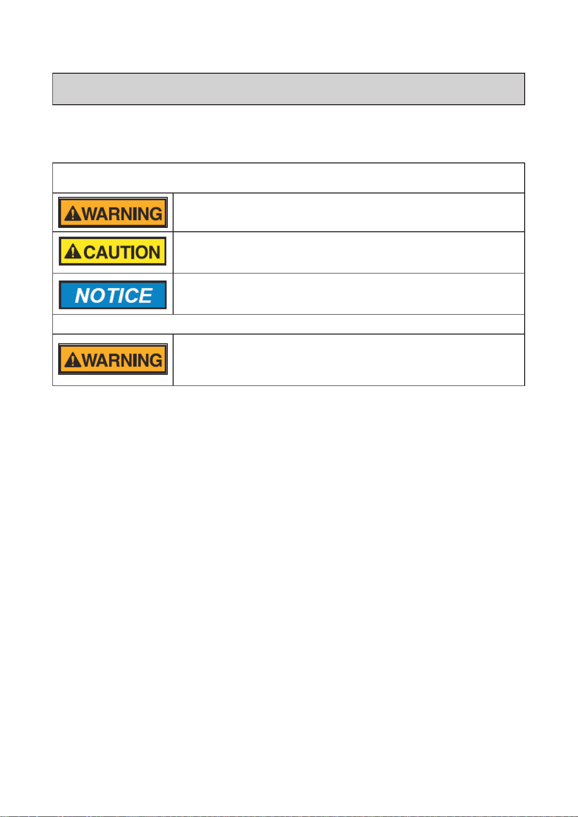
Safety Messages
Indicates a hazardous situation that, if not avoided, could result in death or
serious injury.
Indicates a hazardous situation that, if not avoided, could result in minor or
moderate injury.
Indicates information considered important, but not hazard-related (for
example, messages relating to property damage).
General Precautions
To reduce the risk of serious injury or death, read these instructions
thoroughly and follow all warnings or cautions included in all manuals that
accompanied the product and are attached to the unit. Refer back to these
safety instructions as needed.
● This system should be installed by personnel certied by Johnson Controls, Inc. Personnel must be
qualied according to local, state and national building and safety codes and regulations. Incorrect
installation could cause leaks, electric shock, re or explosion. In areas where Seismic ‘’Performance
requirements are specied, the appropriate measures should be taken during installation to guard against
possible damage or injury that might occur in an earthquake if the unit is not installed correctly, injuries may
occur due to a falling unit.
● Use appropriate Personal Protective Equipment (PPE), such as gloves and protective goggles and,
where appropriate, have a gas mask nearby. Also use electrical protection equipment and tools suited
for electrical operation purposes. Keep a quenching cloth and a re extinguisher nearby during brazing.
Use care in handling, rigging, and setting of bulky equipment.
● When transporting, be careful when picking up, moving and mounting these units. Although the unit may
be packed using plastic straps, do not use them for transporting the unit from one location to another. Do
not stand on or put any material on the unit. Get a partner to help, and bend with your knees when lifting
to reduce strain on your back. Sharp edges or thin aluminum ns on the air conditioner can cut ngers,
so wear protective gloves.
● Do not touch or adjust any safety devices inside the indoor or outdoor units. All safety features,
disengagement, and interlocks must be in place and functioning correctly before the equipment is put
into operation. If these devices are improperly adjusted or tampered with in any way, a serious accident
can occur. Never bypass or jump-out any safety device or switch.
● Johnson Controls, Inc. will not assume any liability for injuries or damage caused by not following steps
outlined or described in this manual. Unauthorized modications to Johnson Controls products are
prohibited as they…
◦ May create hazards which could result in death, serious injury or equipment damage.
◦ Will void product warranties.
◦ May invalidate product regulatory certications.
◦ May violate OSHA standards.
31
i
P5415467
Page 5

Take the following precautions to reduce the risk of property damage.
● Be careful that moisture, dust, or variant refrigerant compounds not enter the refrigerant cycle during
installation work. Foreign matter could damage internal components or cause blockages.
● If air lters are required on this unit, do not operate the unit without the air lter set in place. If the air
lter is not installed, dust may accumulate and breakdown may result.
● Do not install this unit in any place where silicon gases can coalesce. If the silicon gas molecules
attach themselves to the surface of the heat exchanger, the nned surfaces will repel water. As a
result, any amount of condensate can overow from the condensate pan and could run inside of the
electrical box, possibly causing electrical failures.
● When installing the unit in a hospital or other facility where electromagnetic waves are generated
from nearby medical and/or electronic devices, be prepared for noise and electronic interference
Electromagnetic Interference (EMI). Do not install where the waves can directly radiate into the
electrical box, controller cable, or controller. Inverters, appliances, high-frequency medical equipment,
and radio communications equipment may cause the unit to malfunction. The operation of the unit
may also adversely affect these same devices. Install the unit at least 10 ft. (approximately 3m) away
from such devices.
● When a wireless zone controller is used, locate at a distance of at least 3.3 ft. (approximately 1 meter)
between the indoor unit and electric lighting. If not, the receiver part of the unit may have difculty
receiving operation commands.
● Do not install the unit in any location where animals and plants can come into direct contact with the
outlet air stream. Exposure could adversely affect the animals and plants.
● Do not install the unit with any downward slope to the side of the drain boss. If you do, you may have
water owing back which may cause leaks.
● Be sure the condensate hose discharges water properly. If connected incorrectly, it may cause leaks.
● Do not install the unit in any place where oil can seep onto the units, such as table or seating areas in
restaurants, and so forth. For these locations or social venues, use specialized units with oil-resistant
features built into them. In addition, use a specialized ceiling fan designed for restaurant use. These
specialized oil-resistant units can be ordered for such applications. However, in places where large
quantities of oil can splash onto the unit, such as a factory, even the specialized units cannot be used.
These products should not be installed in such locations.
Installation Precautions
To reduce the risk of serious injury or death, the following installation
precautions must be followed.
● When installing the unit into…
▫ A wall: Make sure the wall is strong enough to hold the unit’s weight. It may be necessary to
construct a strong wood or metal frame to provide added support.
▫ A room: Properly insulate any refrigerant tubing run inside a room to prevent “sweating” that can
cause dripping and water damage to wall and oors.
▫ Damp or uneven areas: Use a raised concrete pad or concrete blocks to provide a solid, level
foundation for the unit to prevent water damage and abnormal vibration.
▫ An area with high winds: Securely anchor the outdoor unit down with bolts and a metal frame.
Provide a suitable air bafe.
▫ A snowy area (only for heat pump model): Install the outdoor unit on a raised platform that is
higher than drifting snow. Provide snow vents.
● Do not install the unit in the following places. Doing so can result in an explosion, re, deformation,
corrosion, or product failure.
▫ Explosive or ammable atmosphere
▫ Where re, oil, steam, or powder can directly enter the unit, such as in close proximity or directly
above a kitchen stove.
▫ Where oil (including machinery oil) may be present.
▫ Where corrosive gases such as chlorine, bromine, or sulde can accumulate, such as near a hot
tub or hot spring.
▫ Where dense, salt-laden airow is heavy, such as in coastal regions.
▫ Where the air quality is of high acidity.
▫ Where harmful gases can be generated from decomposition.
ii
4
P5415467
Page 6
● Do not position the condensate pipe for the indoor unit near any sanitary sewers where corrosive
gases may be present. If you do, toxic gases can seep into breathable air spaces and can cause
respiratory injuries. If the condensate pipe is installed incorrectly, water leakage and damage to the
ceiling, oor, furniture, or other possessions may result. If condensate piping becomes clogged,
moisture can back up and can drip from the indoor unit. Do not install the indoor unit where such
dripping can cause moisture damage or uneven locations: Use a raised concrete pad or concrete
blocks to provide a solid, level foundation for the unit to prevent water damage and abnormal
vibration.
● Before performing any brazing work, be sure that there are no ammable materials or open
ames nearby.
● Perform a run test to ensure normal operation. Safety guards, shields, barriers, covers, and protective
devices must be in place while the compressor/unit is operating. During the test run, keep ngers and
clothing away from any moving parts.
● Clean up the site when nished, remembering to check that no metal scraps or bits of wiring have
been left inside the unit being installed.
● During transportation, do not allow the backrest of the forklift to make contact with the unit,
otherwise, it may cause damage to the heat exchanger and also may cause injury when
stopped or started suddenly.
● Remove gas inside the closing pipe when the brazing work is performed. If the brazing ller metal is
melted with remaining gas inside, the pipes will be blown off and it may cause injury.
● Be sure to use nitrogen gas for an airtight test. If other gases such as oxygen gas, acetylene gas or
uorocarbon gas are accidentally used, it may cause explosion or gas intoxication.
After installation work for the system has been completed, explain the “Safety Precautions,” the proper use
and maintenance of the unit to the customer according to the information in all manuals that came with the
system. All manuals and warranty information must be given to the user or left near the Indoor Unit.
Refrigerant Precautions
To reduce the risk of serious injury or death, the following refrigerant
precautions must be followed.
● As originally manufactured, this unit contains refrigerant installed by Johnson Controls. Johnson
Controls uses only refrigerants that have been approved for use in the unit’s intended home country
or market. Johnson Controls distributors similarly are only authorized to provide refrigerants that
have been approved for use in the countries or markets they serve. The refrigerant used in this unit
is identied on the unit’s faceplate and/or in the associated manuals. Any additions of refrigerant into
this unit must comply with the country’s requirements with regard to refrigerant use and should be
obtained from Johnson Controls distributors. Use of any non-approved refrigerant substitutes will void
the warranty and will increase the potential risk of injury or death.
● If installed in a small room, take measures to prevent the refrigerant from exceeding the maximum
allowable concentration in the event that refrigerant gases should escape. Refrigerant gases can
cause asphyxiation (0.42 kg/m3 based on ISO 5149 for R410A). Consult with your distributor for
countermeasures (ventilation system and so on). If refrigerant gas has leaked during the installation
work, ventilate the room immediately.
● The design pressure for this product is 601 psi (4.15MPa). The pressure of R410A refrigerant is 1.4
times higher than that of the refrigerant R22. Therefore, the refrigerant piping for R410A shall be
thicker than that for R22. Make sure to use the specified refrigerant piping. If not, the refrigerant
piping may rupture due to an excessive refrigerant pressure. Besides, pay attention to the piping
thickness when using copper refrigerant piping. The thickness of copper refrigerant piping differs
depending on its material.
● The refrigerant R410A is adopted. The refrigerant oil tends to be affected by foreign matters such
as moisture, oxide lm, (or fat). Perform the installation work with care to prevent moisture, dust, or
different refrigerant from entering the refrigerant cycle. Foreign matter can be introduced into the
cycle from such parts as expansion valve and the operation may be unavailable.
● To avoid the possibility of different refrigerant or refrigerant oil being introduced into the cycle, the
sizes of the charging connections have been changed from R407C type and R22 type. It is necessary
to prepare the appropriate tools before performing the installation work.
● Use refrigerant pipes and joints which are approved for use with R410A.
● A compressor/unit comprises a pressurized system. Never loosen threaded joints while the system is
5
P5415467
iii
Page 7

under pressure and never open pressurized system parts.
● Before installation is complete, make sure that the refrigerant leak test has been performed. If
refrigerant gases escape into the air, turn OFF the main switch, extinguish any open ames and
contact your service contractor. Refrigerant (Fluorocarbon) for this unit is odorless. If the refrigerant
should leak and come into contact with open ames, toxic gas could be generated. Also, because the
uorocarbons are heavier than air, they settle to the oor, which could cause asphyxiation.
● When installing the unit, and connecting refrigerant piping, keep all piping runs as short as
possible, and make sure to securely connect the refrigerant piping before the compressor starts
operating. If the refrigerant piping is not connected and the compressor activates with the stop
valve opened, the refrigerant cycle will become subjected to extremely high pressure, which can
cause an explosion or re.
● Tighten the are nut with a torque wrench in the specied manner. Do not apply excessive force to the
are nut when tightening. If you do, the are nut can crack and refrigerant leakage may occur.
● When maintaining, relocating, and disposing of the unit, dismantle the refrigerant piping after the
compressor stops.
● When pipes are removed out from under the piping cover, after the insulation work is completed,
cover the gap between the piping cover and pipes by a packing (eld-supplied). If the gap is not
covered, the unit may be damaged if snow, rain water or small animals enter the unit.
● Do not apply an excessive force to the spindle valve at the end of opening. Otherwise, the spindle
valve ies out due to refrigerant pressure. At the run test, fully open the gas and liquid valves,
otherwise, these devices will be damaged. (It is closed before shipment.)
● If the arrangement for outdoor units is incorrect, it may cause owback of the refrigerant and result in
failure of the outdoor unit.
● The refrigerant system may be damaged if the slope of the piping connection kit exceeds +15o.
Electrical Precautions
Take the following precautions to reduce the risk of electric shock, re or
explosion resulting in serious injury or death.
● Highly dangerous electrical voltages are used in this system. Carefully refer to the wiring diagram
and these instructions when wiring. Improper connections and inadequate grounding can cause
serious injury or death.
● Perform all electrical work in strict accordance with this installation and maintenance manual and all
the relevant regulatory standards.
● Before servicing, open and tag all disconnect switches. Never assume electrical power is
disconnected. Check with meter and equipment.
● Only use electrical protection equipment and tools suited for this installation.
● Use specied cables between units.
● The new air conditioner may not function normally in the following instances:
▫ If electrical power for the new air conditioner is supplied from the same transformer as the device*
referred to below.
▫ If the power source cables for this device* and the new air conditioner unit are located in close
proximity to each other.
Device*: (Example): A lift, container crane, rectier for electric railway, inverter power
device, arc furnace, electric furnace, large-sized induction motor and large-sized switch.
Regarding the cases mentioned above, surge voltage may be inducted into the power supply
cables for the packaged air conditioner due to a rapid change in power consumption of the
device and an activation of a switch.
Check eld regulations and standards before performing electrical work in order to protect the
power supply for the new air conditioner unit.
iv
6
P5415467
Page 8

● Communication cabling shall be a minimum of 18-Gauge, 2-Conductor, Stranded Copper. Shielded
cable must be considered for applications and routing in areas of high EMI and other sources of
potentially excessive electrical noise to reduce the potential for communication errors. When shielded
cabling is applied, proper bonding and termination of the cable shield is required as per Johnson
Controls guidelines. Plenum and riser ratings for communication cables must be considered per
application and local code requirments.
● Use an exclusive power supply for the air conditioner at the unit’s rated voltage.
● Be sure to install circuit breakers (ground fault interrupter, isolating switch, molded case circuit
breaker and so on), with the specied capacity. Ensure that the wiring terminals are tightened securely
to recommended torque specications.
● Clamp electrical wires securely with a cable clamp after all wiring is connected to the terminal block.
In addition, run wires securely through the wiring access channel.
● When installing the power lines, do not apply tension to the cables. Secure the suspended cables at
regular intervals, but not too tightly.
● Make sure that the terminals do not come into contact with the surface of the electrical box. If the
terminals are too close to the surface, it may lead to failures at the terminal connection.
● Turn OFF and disconnect the unit from the power source when handling the service connector. Do not
open the service cover or access panel to the indoor or outdoor units without turning OFF the main
power supply.
● After ceasing operation, be sure to wait at least ve minutes before turning off the main power
switch. Otherwise, water leakage or electrical breakdown may result. Disconnect the power source
completely before attempting any maintenance for electrical parts. Check to ensure that no residual
voltage is present after disconnecting the power source.
● Do not clean with, or pour water into, the controller as it could cause electric shock and/or damage the
unit. Do not use strong detergent such as a solvent. Clean with a soft cloth.
● Check that the ground wire is securely connected. Do not connect ground wiring to gas piping, water
piping, lighting conductor, or telephone ground wiring.
● If a circuit breaker or fuse is frequently activated, shut down the system and contact your
service contractor.
● Perform all electrical work in accordance with this manual and in compliance with all regulations and
safety standards.
● Do not open a service access cover or panel of an indoor or outdoor unit without rst turning OFF the
power at the main power supply.
● Residual voltage can cause electric shock. At all times, check for residual voltage after disconnecting
from the power source before starting work on the unit.
● This equipment can be installed with a Ground Fault Circuit Breaker (GFCI), which is a recognized
measure for added protection to a properly grounded unit. Install appropriate sized breakers/fuses/
overcurrent protection switches, and wiring in accordance with local, state and NEC codes and
requirements. The equipment installer is responsible for understanding and abiding by applicable
codes and requirements.
v
7
P5415467
Page 9
Installation and Maintenance
2.
Installation
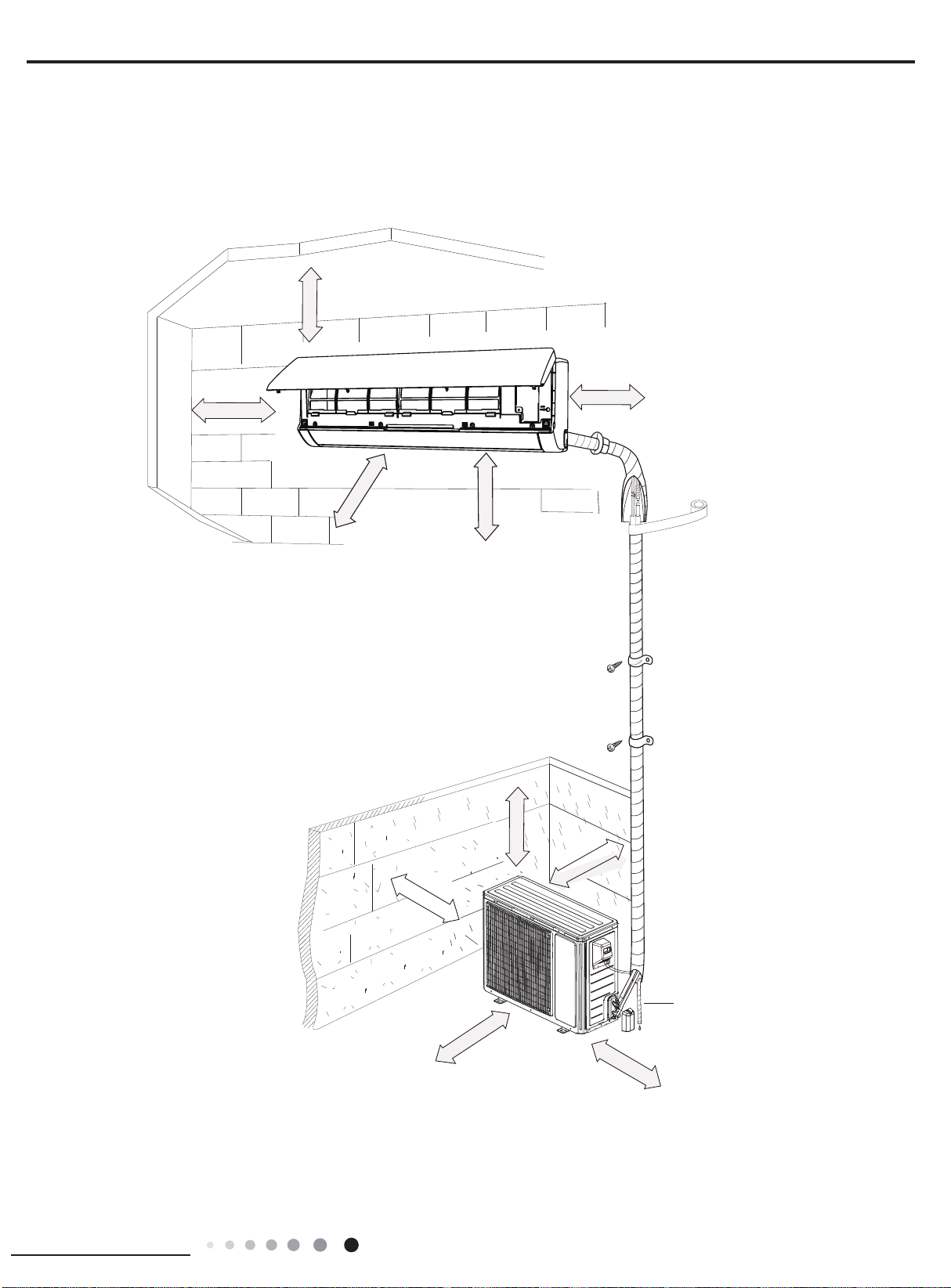
2.1 Installation Dimension Diagram
At least 5 8/9 inch
Space to the ceiling
Space to the wall
At least 5 8/9 inch
Space to the wall
At least 5 8/9 inch
roolf eht ot ecapS
At least 118 inch
Space to the obstruction
Space to the wall
At least 11 4/5 inch
At least 98 3/7 inch
Space to the obstruction
At least 19 2/3 inch
Space to the obstruction
At least 11 4/5 inch
Space to the obstructio
At least 78 3/5 inch
Condensate pipe
Space to the obstruction
At least 19 2/3 inch
1
Page 10
Installation and Maintenance
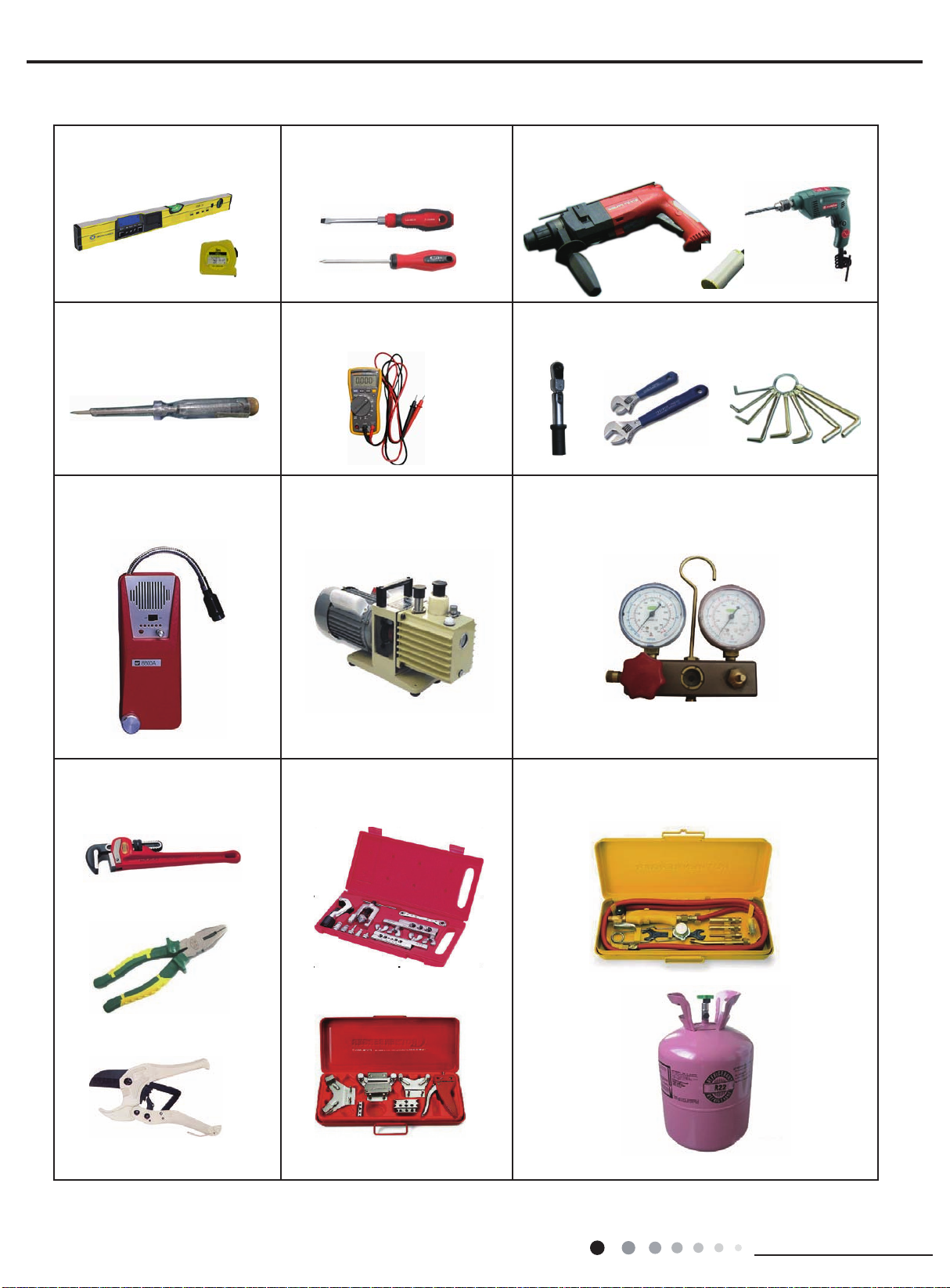
2.2 Main Tools for Installation and Maintenance
1. Level meter, measuring tape
4. Electroprobe
7. Electronic leakage detector
2. Screw driver
5. Universal meter
8. Vacuum pump
3. Impact drill, drill head, electric drill
6. Torque wrench, open-end wrench, inner
hex wrench
9. Manifold gauge
10. Pipe pliers, pipe cutter
11. Pipe expander, pipe bender
12. Soldering appliance, refrigerant container
2
Page 11
Installation and Maintenance
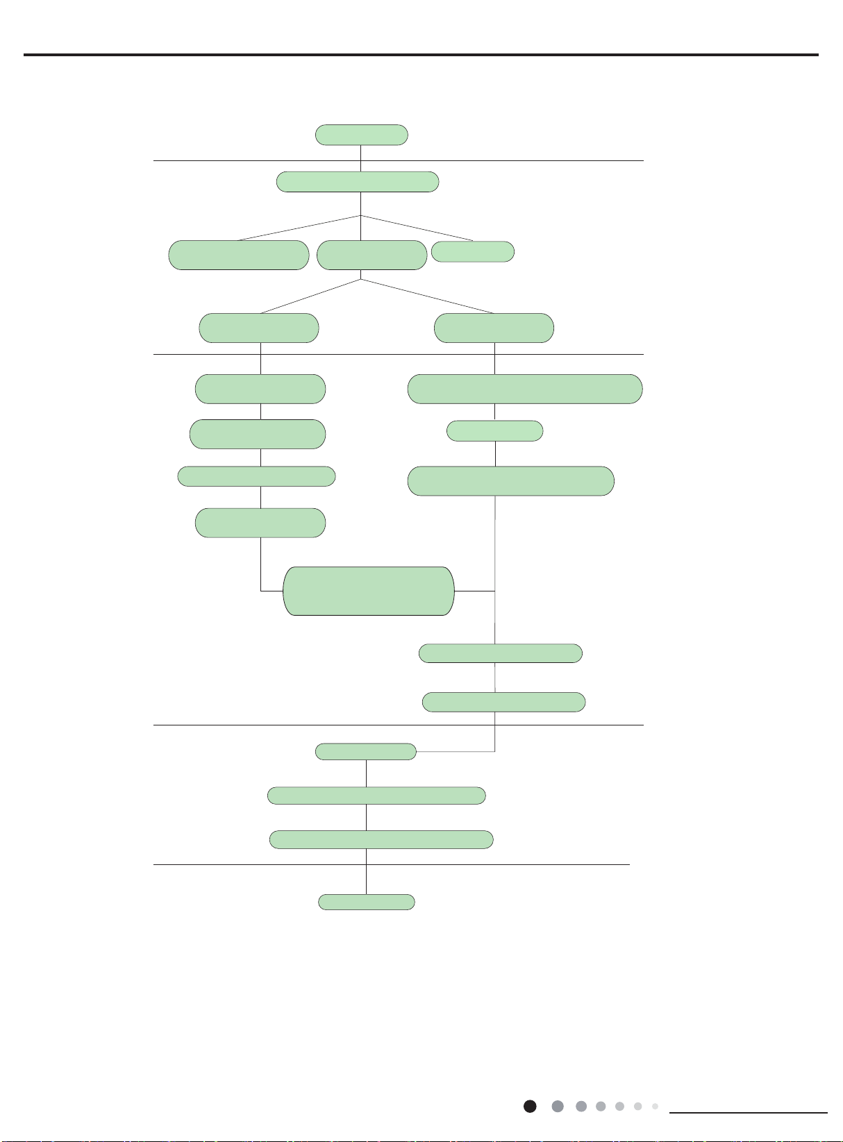
2.3 Installation Procedures
Start installation
Preparation before installation
Read the requirements
for electric connection
Select indoor unit
installation location
Install wall-mounting
frame, drill wall holes
Connect pipes of indoor
unit and drainage pipe
Connect wires of indoor unit
Bind up pipes and
hang the indoor unit
Make the bound pipes pass
through the wall hole and then
connect outdoor unit
Select installation
location
Prepare tools
Select outdoor unit
installation location
Install outdoor unit mount
(select it according to the actual situation)
Mount outdoor unit
Install drainage joint of outdoor unit
(only for cooling and heating unit)
Connect pipes of outdoor unit
Connect wires of outdoor unit
Arrange the pipes
Vacuum pumping and leakage detection
Check after installation and test operation
Finish installation
Note: This flow is only for reference; please find more detailed installation steps in this section.
3
Page 12
Installation and Maintenance
2.4 Installation - Checking Parts
No. Name No. Name
1 Indoor unit 8 Sealant
2 Outdoor unit 9 Wrapping tape
3 Connection pipe 10
4 Drainage pipe 11 Fixing screw
Wall-mounting
5
frame
Connecting
6
cable(power cord)
7 Wall pipe
Note:
1. Please contact the local agent for installation.
2. Don't use unqualied power cord.
.5 Selection of Installation Location
2
Basic Requirement:
1.
Installing the unit in the following places may cause
malfunction. If it is unavoidable, please consult the local dealer:
(1) Areas with strong heat sources, vapors, flammable or
explosive gas, or volatile objects spread in the air.
(2) Areas with high-frequency devices
machine, medical equipment).
(3) Areas near coast.
(4) Areas with oil or fumes in the air.
(5) Areas with sulfureted gas.
(6) Other places with special circumstances.
2. Indoor Unit:
(1) There should be no obstruction near air inlet and air outlet.
(2) Select a location where the condensation water can be
dispersed easily and won't affect other people.
(3) Select a location which is convenient to connect the
outdoor unit and near the power socket.
(4)
Select a location which is out of reach for children.
(5) The location should be able to withstand the weight of
indoor unit and won't increase noise and vibration.
(6) The appliance must be installed 98 3/7 inch above oor.
(7) Don't install the indoor unit right above the electric
appliance.
(8) The appliance should not be installed in a laundry area.
3. Outdoor Unit:
1.Select a location where the noise and outow air emitted by
the outdoor unit will not affect neighborhood.
2.The location should be well ventilated and dry, in which the
outdoor unit won't be exposed directly to sunlight or strong
wind.
3.The location should be able to withstand the weight of
outdoor unit.
Make sure that the installation complies with requirements
4.
iof the installation dimensions diagram.
5.Select a location which is out of reach for children and far
away from animals or plants.If it is unavoidable, please add
fence for safety purposes.
Support of outdoor
unit
Drainage plug(cooling
12
and heating unit)
Owner’s manual,
13
remote controller
(such as welding
2.6 Electric Connection Requirement
1. Safety Precaution
(1) All electric safety regulations must be followed when
installing the unit.
(2) Use proper power supply circuit and air switch in
accordance with local safety regulations.
(3) The power supply must be sized to meet the requirements
of air conditioning unit. Incorrect sizing/wiring may result in
electric shock,fire hazard or malfunction.
Air-conditioner Air switch capacity
09/12K 16A
18K 20A
24K 30A
(4) Properly connect the live wire, neutral wire and grounding
wire of power socket.
(5) Be sure to cut off the main power supply before
performing any electrical work.
(6) Do not turn power back on until installation is complete.
(7) For appliances with type Y attachment,the instructions
shall contain the substance of thefollowing.If the supply cord is
damaged, it must be replaced by the manufacturer, its
service agent or a qualified technician to avoid any shock
hazards.
(8) The temperature of refrigerant circuit will be high, please
keep the interconnection cable away from the copper tube.
Grounding Requirements:
2.
(1) The air conditioning unit must be properly grounded with
a specialized grounding device by a certified technician.
Please make sure it is always grounded effectively, otherwise
it may cause electric shock.
(2) The yellow-green wire in air conditioner is grounding wire,
which can't be used for other purposes.
(3) The grounding resistance should comply with national
electric safety regulations.
(4) The unit must be positioned so that the plug is
accessible.
(5) An all-pole disconnect switch having a contact separation of at
least 1/8 inch in all poles should be connected in fixed wiring.
(6) Including an air switch with suitable capacity, please note the
following table. Air switch should be included magnet buckle and
heating buckle function, it can protect the circuitshort and
overload. (Caution: Please do not use only the fuse to
protect the circuit.)
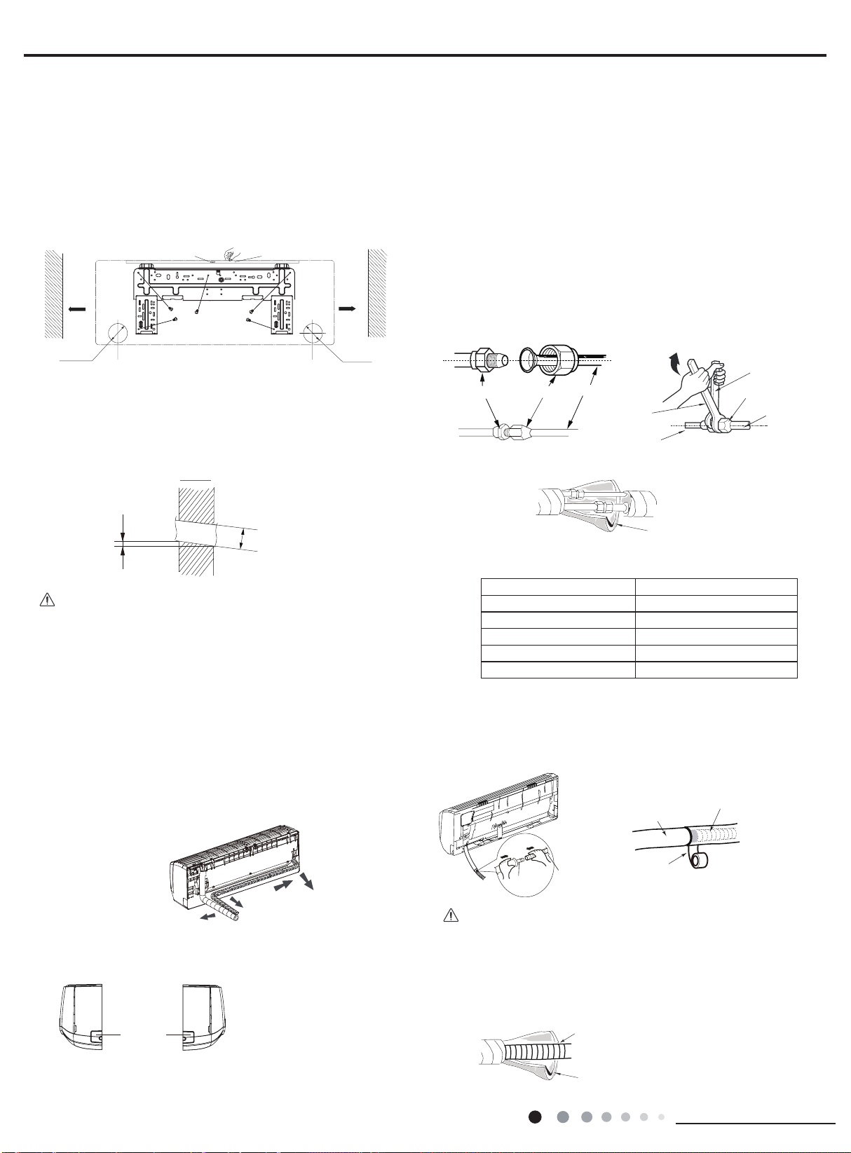
2.7 Installation of Indoor Unit
1. Choosing Installation Iocation
Recommend installation location to the client based on field
conditions; then proceed after client approval.
2. Install Wall-mounting Frame
(1) Hang the wall-mounting frame on the wall; adjust it in
horizontal position with the level meter and then point out the
screw xing holes on the wall.
(2) Drill the screw xing holes on the wall with impact drill (the
specification of drill head should be the same as the plastic
expansion particle) and then ll the plastic expansion particles
4
Page 13
Installation and Maintenance
Rear left
h
Indoor
Outdoor
in the holes.
Wall
Wall
(Rear piping hole)
(Rear piping hole)
Tape
Outlet pipe
Torque wrenc
Open-end
Drain hose
e
(3) Fix the wall-mounting frame on the wall with tapping screws
(ST4.2X25TA) and then check if the frame is rmly installed by
pulling the frame. If the plastic expansion particle is loose,
please drill another xing hole nearby.
3. Install Wall-mounting Frame
(1) Choose the position of piping hole accor
ding to the direction
of outlet pipe. The position of piping hole should be a little
lower than the wall-mounted frame.(As shown in Fig.1)
Space
to the
wall
5 8/9inch
above
Mark on the middle of it
Gradienter
Space
to the
wall
5 8/9inch
above
5. Connect the Pipe of Indoor Unit
(1) Aim the pipe joint at the corresponding bellmouth.(As
shown in Fig.5)
(2) Pretightening the union nut with hand.
(3) Adjust the torque force by referring to the following sheet.
Place the open-end wrench on the pipe joint and place the
torque wrench on the union nut. Tighten the union nut
with torque wrench.(As shown in Fig.6)
(4) Wrap the indoor pipe and joint of connection pipe with
insulating pipe, and then wrap it with tape.(As shown in Fig.7)
(5) If a 18k indoor unit is to be connected with a DHM or
DHW outdoor unit, a transitional pipe joint (provided)
should be added at the pipe joint of indoor unit evaporator
assy as the pipe joint of evaporator assy adopts pipe
diameter of Φ5/8. Please refer to step 1-4 during installation.
Left
Ф2 3/4inch Ф2 3/4inch
Fig.1
(2) Open a piping hole with the diameter of Φ2
Right
3/4inch on the
selected outlet pipe position.In order to drain smoothly, slant
the piping hole on the
wall slightly downward to the
outdoor side with the gradient of 5-10°.(As shown in Fig.2)
5-10
°
Φ2 3/4inc
Fig.2
Note:
(1) Pay attention to dust prevention and take relevant safety
measures when opening the hole.
(2) The plastic expansion particles are not provided and should
be bought locally.
4. Outlet Pipe
(1) The pipe can be led out in the direction of right, rear right,
left or rear left.(As shown in Fig.3)
(2) When selecting leading out the pipe from left or right, please
cut off the corresponding hole on the bottom case.(As show in
Fig.4)
wrench
Fig.7
Pipe
Union nut
h
Indoor pipe
Insulating pipe
Union nutPipe joint
Fig.5 Fig.6
Refer to the following table for torque tightening:
Hex nut diameter(inch) Tightening torque(ft·Ibf)
Φ1/4 11.10~14.75
Φ3/8 20.12~29.50
Φ1/2 33.19~40.56
Φ5/8 44.24~47.94
Φ3/4 51.32~55.31
6. Install Drain Hose
(1) Connect the condensate hose to the outlet pipe of indoor
unit.(As shown
in Fig.8)
(2) Bind the joint with tape.(As show in Fig.9)
Condensate hose
Pipe
5
Fig.3
Right
Left Right
Cut off
the hole
Left
Rear right
Fig.4
pipe
Condensate hose
Fig.9
Outlet
Fig.8
Note:
(1) Add insulating pipe in the indoor condensate hose in
order to prevent condensation.
(2) The plastic expansion particles are not provided.
(As shown in Fig.10)
Insulating pip
Fig.10
Page 14
Installation and Maintenance
Indoor power cord
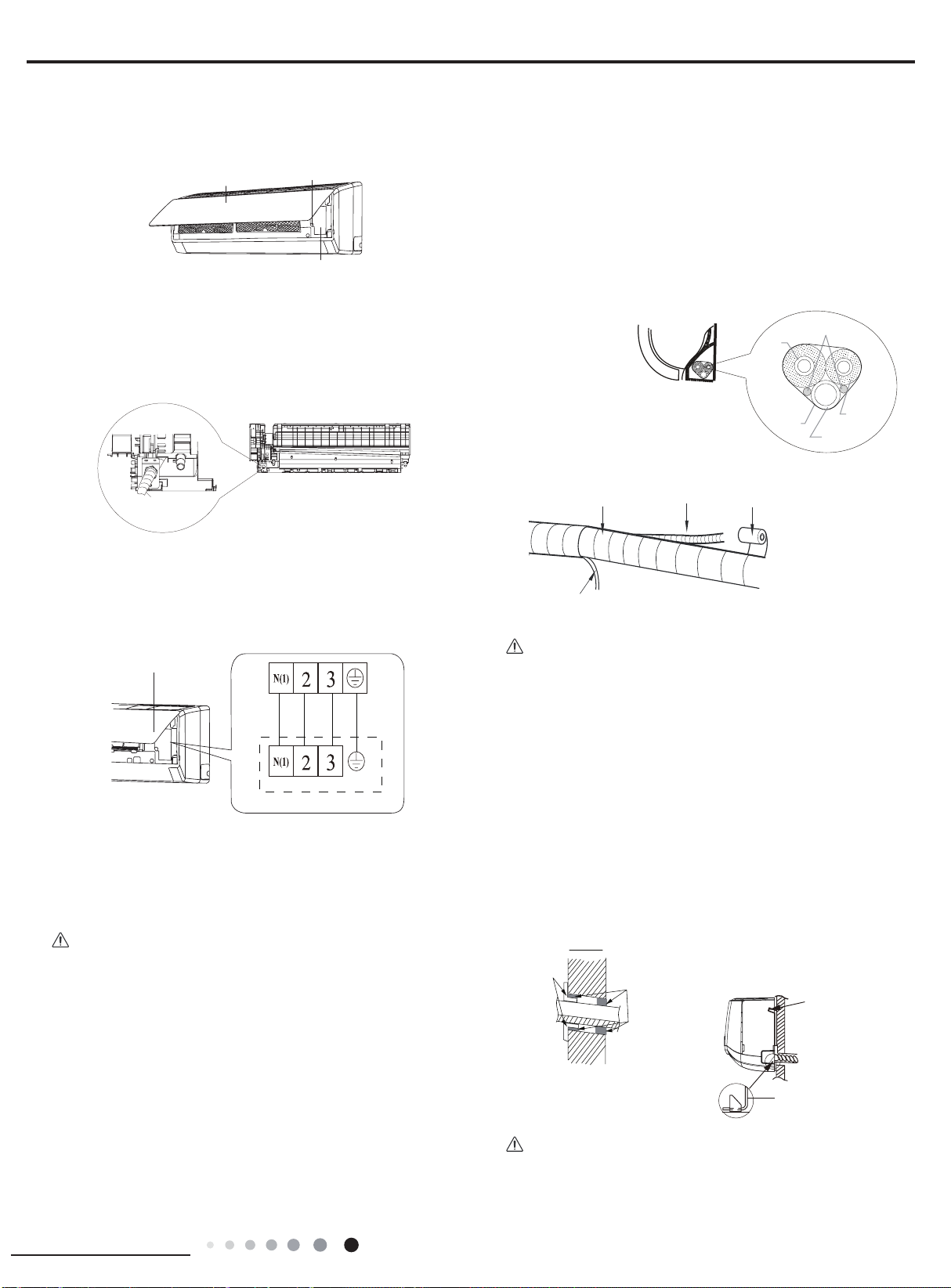
7. Connect Wire of Indoor Unit
Indoor
Outdoor
Wall pipe
Upper hook
wall-mounting frame
Wiring cover
Screw
(1) Open the panel, remove the screw on the wiring cover
and then take down the cover.(As shown in Fig.11)
Panel
Fig.11
8. Bind up Pipe
(1) Bind up the connection pipe, power cord and
condensate hose with the band.(As shown in Fig.14)
(2) Reserve a certain length of drain hose and power cord
for installation when binding them. When binding to a certain
degree, separate the indoor power and then separate the
condensate hose.(As shown in Fig.15)
(3) Bind them evenly.
(4) The liquid pipe and gas pipe should be bound separately at
the end.
(2) Fix the wire crossing board on connection wire sleeve at
the bottom case; let the connection wire sleeve go through the
wire crossing hole at the back of indoor unit, and then pull it out
from the front.(As shown in Fig.12)
connection wire sleeve
Fig.12
(3) Remove the wire clip; connect the power connection wire
to the wiring terminal; tighten the screw and then fix the power
connection wire with wire clip.(As shown in Fig.13)
Wiring Cover
Outdoor unit
Fig.13
(4) Put wiring cover back and then tighten the screw.
(5) Close the panel.
Indoor and
outdoor power cord
Gas
pipe
Band
Band
Liquid
pipe
Condensate hose
Fig.14
Connection pipe
Indoor unit
Condensate hose
Fig.15
Note:
(1) The power cord and control wire can't be crossed or
winding.
(2) The condensate hose should be bound at the bottom.
9. Hang the Indoor Unit
(1) Put the bound pipes in the wall pipe and then make them
pass through the wall hole.
(2) Hang the indoor unit on the wall-mounting frame.
(3) Stuff the gap between pipes and wall hole with sealing gum.
(4) Fix the wall pipe.
(As show in Fig.16)
(5) Check if the indoor unit is installed firmly and closed to the
wall.(As shown in Fig.17)
Note:
(1) All wires of indoor unit and outdoor unit should be
connected by a professional.
(2) If the length of power connection wire is insufcient, please
contact the supplier for a new one. Avoid extending the wire by
yourself.
(3) For the air conditioning unit a with plug, the plug
should be reachable after finishing installation.
(4) For the air conditioning unit without a plug, an air switch
must be installed in the line. The air switch should be allpole parting and the contact parting distance should be more
than 3/32 inch.
Fig.17
Sealant
Fig.16
Lower hook of
Note:
Do not bend the condensate hose too excessively in order to
prevent blocking.
6
Page 15
Installation and Maintenance
The drain hos
Union nut
Foot holes
Foot holes
2.8 Installation of Outdoor Unit
Wall
Drain hose
A
r
Outdoor drain joint
Drain ven
Installupport of Outdoor Unit(select it according to the
1.
actual installation situation)
(1) Select installation location according to the house structure.
(2) Secure
with expansion screws.
(1) Take sufficient protective measures when installing the
outdoor unit.
(2) Make sure the support can withstand at least four times the
unit weight.
(3) The outdoor unit should be installed at least 1 1/6 inch
above the oor in order to install drain joint.(As show in Fig.18)
(4) For the unit with cooling capacity of 2300W~5000W, 6
expansion screws are needed; for the unit with cooling capacity
of 6000W~8000W, 8 expansion screws are needed; for the
unit with cooling capacity of 10000W~16000W, 10 expansion
screws are needed.
the support of outdoor unit on the selected location
Note:
Refer to the following table for torque tightening:
Hex nut diameter(inch) Tightening torque(ft·Ibf)
Φ1/4 11.10~14.75
Φ3/8 20.12~29.50
Φ1/2 33.19~40.56
Φ5/8 44.24~47.94
Φ3/4 51.32~55.31
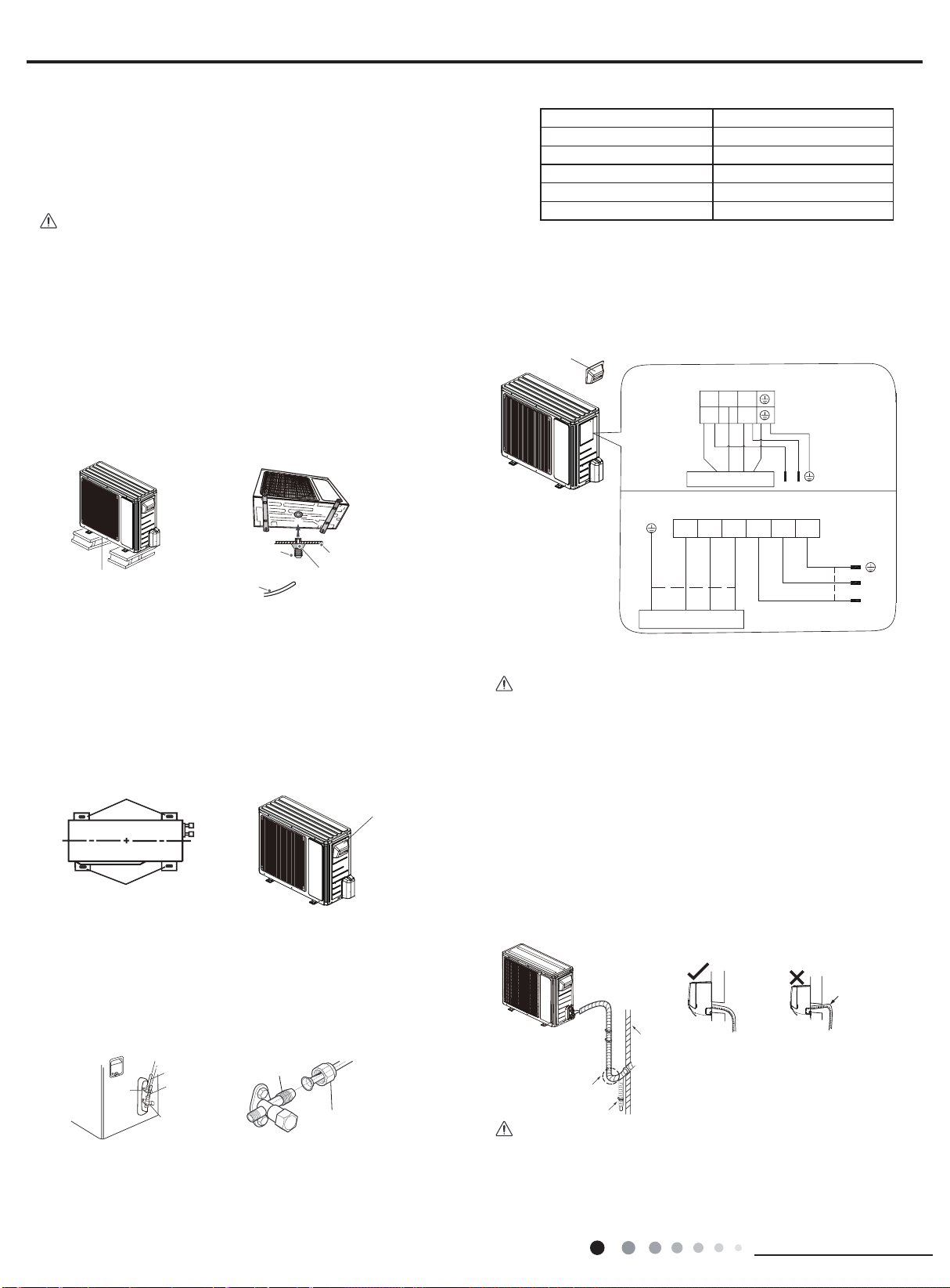
5. Connect Outdoor Electric Wire
(1) Remove the c
onnection wire sleeve go through the two
holes of bafe; tighten the connection joint of sleeve and bafe;
remove the wire clip; connect the power connection wire and
power cord to the wiring terminal; fix them with screws.(As
shown in Fig.23)
Handle
09/12K
N(1)
223
L1L1L2
t least 1 1/6 inch above the floo
t
Condensate hose
Chassis
Fig.18 Fig.19
2. Install Drain Joint(only for cooling and heating unit)
(1) Connect the outdoor drain joint into the hole on the
chassis.(2) Connect the condensate hose into the drain
vent.(As shown in Fig.19)
3. Fix Outdoor Unit
(1) Place the outdoor unit on the support.
(2)
Fix the foot holes of outdoor unit with
bolts.(As shown in Fig.20)
Handle
Fig.20
Fig.21
4. Connect Indoor and Outdoor Pipes
(1) Remove the screw on the right handle of outdoor unit and
then remove the handle.(As show in Fig.21)
(2) Remove the screw cap of
valve and aim the pipe joint at the
bellmouth of pipe.(As shown in Fig.22)
Fig.23
G
N(1)
Indoor unit connection
Indoor unit connection
18/24K
3
Power
L1
L2
L2
G
L2
L1
(2) Fix the power connection wire and power cord with wire clip.
Note:
(1) After tightening the screw, pull the power cord slightly to
check if it is rm.
(2) Never cut the power connection wire to prolong or shorten
the distance.
Arrange the Pipes
6.
(1) The pipes should be placed along the wall, bent reasonably
and hidden. The semidiameter of bending the pipe is 4 in.
(2) If the outdoor unit is higher than the wall hole, a U-shaped
curve in the pipe is a must before pipe goes into the room, in
order to prevent rain from getting into the room.(As shown in
Fig.24)
can't raise
upwards
Power
Liquid pipe
Liquid
valve
gas pipe
gas valve
Fig.22
(3) Pretightening the union nut with hand.
(4) Tighten the union nut with torque wrench .
7
Pipe joint
Fig.24
U-shaped curve
Note:
(1) The through-wall height of drain hose shouldn't be higher
than the outlet pipe hole of indoor unit.(As shown in Fig.25)
(2) Slant the condensate hose slightly downwards. The
condensate hose can't be curved, raised or fluctuant.(As
shown in Fig.26)
Fig.25
Page 16

Installation and Maintenance
(3) The water outlet can't be placed in water in order to drain
Refrigerant charging
vent
Nut of refrigerant
Charging vent
outlet can't be
The water outlet
can't be placed
in water
smoothly.(As show in Fig.27)
The drain hose can't be fluctuant
The drain hose
can't be fluctuant
The water
fluctuant
Fig.27
Fig.26
2.9 Vacuum Pump/Leak Detection
1. Use Vacuum Pump
(1) Remove the valve caps on the liquid valve and gas valve
and the nut of refrigerant charging vent.
(2) Connect the charging hose of manifold gauge to the
refrigerant charging vent of gas valve and then connect the
other charging hose to the vacuum pump.
(3) Open the manifold gauge completely and operate for
10-15min to check if the pressure of manifold gauge remains in
-0.1MPa.
(4) Close the vacuum pump and maintain this status for 1-2min
to check if the pressure of manifold gauge remains in
-0.1MPa. If the pressure decreases, there may be leakage.
(5) Remove the manifold gauge, open the valve core of liquid
valve and gas valve completely with inner hex wrench.
(6) Tighten the screw caps of valves and refrigerant charging
vent.(As shown in Fig.28)
Liquid valve
Gas valve
Inner hex
wrench
Fig.28
Manifold gauge
Valve cap
Vacuum pump
Close
Open
Lo Hi
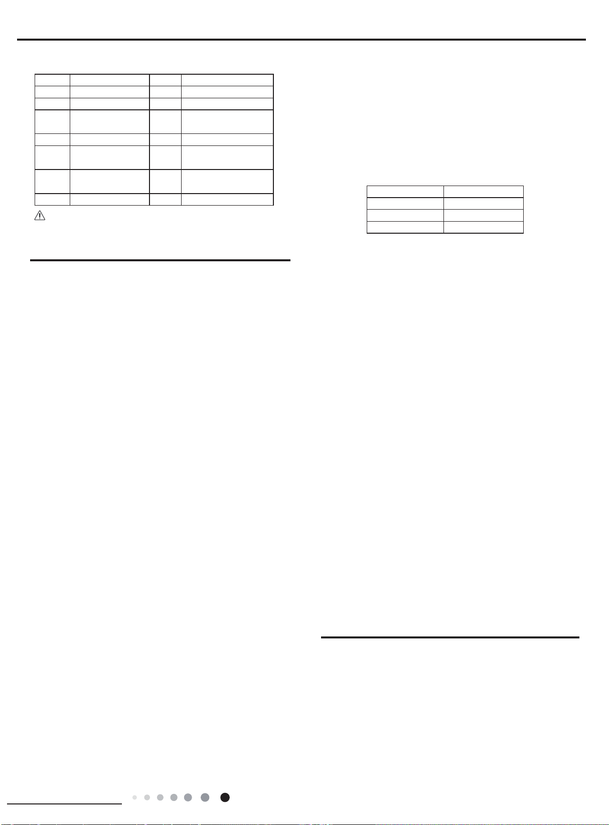
2.10 Post Installation Testing
1. Check after Installation
Check according to the following requirements after
finishing installation.
No. Items to be checked Possible malfunction
Has the unit been
1
installed rmly?
Have you done the
2
refrigerant leakage test?
Is heat insulation of
3
pipeline sufcient?
4 Is water drained well?
Is the voltage of power
supply according to the
5
voltage marked on the
nameplate?
Is electric wiring and
6
pipeline installed
correctly?
Is the unit grounded
7
securely?
Does the power cord
8
follow the specication?
Is there any obstruction
9
in air inlet and air outlet?
The dust and
sundries caused
10
during installation are
removed?
The gas valve and liquid
11
valve of connection pipe
are open completely?
2. Test Operation
(1) Preparation of test operation
● The client approves the air conditioner installation.
● Specify the important notes for air conditioner to the client.
(2) Method of test operation
● Put through the power, press ON/OFF button on the remote
controller to start operation.
● Press MODE button to select AUTO, COOL, DRY, FAN and
HEAT to check operations.
● If the ambient temperature is lower than 16
conditioner can’t start cooling.
The unit may drop, shake or
emit noise.
It may cause insufcient cooling
(heating) capacity.
It may cause condensation and
water dripping.
It may cause condensation and
water dripping.
It may cause malfunction or
damage the parts.
It may cause malfunction or
damage the parts.
It may cause electric shock.
It may cause malfunction or
damage the parts.
It may cause insufcient cooling
(heating).
It may cause malfunction or
damaging the parts.
It may cause insufficient
cooling (heating).
, the air
℃
2. Leakage detection
(1) Check for leaks using the leak detector:
(2) With soap water:
if a leak detection tool is unavailable, use soap water to detect
any leak. Apply soap water to the suspected leak position and
observe for 3 minutes, if bubbles appear then there is a leak.
8
Page 17

Installation and Maintenance
Troubleshooting
3.
3.1 Precautions before Performing Inspection or Repair
Be cautious during installation and maintenance. Follow safety
due to drop from high attitude.
Static maintenance is is performed while the unit is d-energized.
*
For static maintenance, make sure that the unit is de-energized and the plug is disconnected.
*dynamic maintenance is the maintenance during energization of the unit.
Before dynamic maintenance, check that the unit is properly grounded using a voltage tester. Check the copper piping and housing of
the unit to ensure there are no voltage leaks. After ensure insulation place and the safety, the maintenance can be performed.
Take sufficient care to avoid directly touching any of the circuit parts without first turning off the power.
At times such as when the circuit board is to be replaced, place the circuit board assembly in a vertical position.
Please follow troubleshooting procedures as described below.(Refer to the check points written on the wiring diagrams attached to the
indoor/outdoor units.)
regulations at all times to avoid electric shock and casualty or even death
No. Troubleshooting procedures
1 Conrmation
Judgment by Flashing LED of Indoor/Outdoor Unit
2
3 How to Check the Main Parts
NOTE:
A large-capacity electrolytic capacitor is used in the outdoor unit controller(inverter).Therefore,if the power supply is
turned off, charge(charging voltage DC280V to 380V)remains and discharging takes a lot of time. After turning off the power source,if
touching the charging section before discharging, an electrical shock may be caused.
Discharging method
(1)remove the inverter cover(Outoor Unit)
(2)As shown below,connect the discharge rescharge resistance(approx.100Ω,20W) or plug of the soldering iron to voltage between + -
terminals of the electrolytic capacitor (test 3*D* and *E* point) on PC Board for 30s ,and then perform discharging
9
Page 18

Installation and Maintenance
3.2 Confirmation
(1)Conrmation of Power Supply
Conrm that the power breaker operates(ON) normally;
(2)Conrmation of Power Voltage
Conrm that power voltage is AC 208-230 ±10%. If power voltage is not in this range, the unit may not operate normally.
3.3 Flashing LED of Indoor/Outdoor Unit and Primary Judgment
10
Page 19

Installation and Maintenance
(1)Models:09/12K:
Malfunction and Status Display Table
15 times
No. Malfunction Name
1 Malfunction of Circuit for zero cross detection U8
2 Malfunction protection for jumper cap C5
3 No feedback from indoor motor H6
Indoor ambient temp sensor has open or short
4
Indoor evaporator temp sensor has open or
5
Liquid valve temp sensor has open or short
6
7
8 Module temp sensor has open or short circuit P7
9
10
11
12
13
14
15
16 Demagnetization protection of compressor HE
17 Malfunction of voltage drop of DC bus bar U3
18 Module temperature protection P8
19
20 Malfunction of charging for capacitor PU
21 High pressure protection for the system E1
22
23
24
25 Overspeed (for commercial air conditioner)
26 Malfunction of
27
28
29
30
31 Thermal overload protection for compressor H3
32 Non-match between indoor and outdoor units LP
33 Malfunction of memory chip
Gas valve temp sensor has open or short
Outdoor ambient temp sensor has open or
Outdoor inlet pipe temp sensor of condenser
has open or circuit (for commercial use)
Outdoor middle pipe temp sensor of condenser
Outdoor outlet pipe of condenser has open or
Outdoor discharge temp sensor has open or
Communication malfunction of indoor and
Malfunction of circuit for detecting phase
Lack of refrigerant or block protection for the
Reset of drive module (for commercial air
AC contactor protection (for commercial air
Temperature drift protection(for commercial air
Sensor connection protection (for commercial
Communication malfunction for drive board(for
has open or short circuit
short circuit (for commercial use)
current of compressor
system (not applicable to residential air
Low pressure protection for the system
Lock of compressor (for commercial air
commercial air conditioner)
circuit
short circuit
circuit
circuit
short circuit
short circuit
outdoor units
conditioner)
reserved
conditioner)
conditioner)
conditioner)
conditioner)
air conditioner)
Malfunction
Type
Malfunction
of
hardware
Display
Nixie
Tube
F1
F2
b5
b7
F3
A5
F4
A7
F5
E6
U1
F0
E3
LE / / /
P0 / / /
LF
PF
P9 / / /
PE / /
Pd / / /
P6
EE
Display of Malfunction of Indoor Unit
Status of LED Lamp
LED
Lamp
for
Operation
Blinks
for 17
times
Blinks
for 15
times
Blinks
for 11
times
Blinks
for 6
times
Blinks
once
Blinks
for 3
times
/ / /
/ / /
Blinks
for 16
times
LED Lamp
for
Cooling
Blinks
once
Blinks
twice
Blinks for
19 times
Blinks for
22 times
Blinks for
3 times
Blinks for
4 times
Blinks for
5 times
Blinks for
10 times
LED Lamp
for
Heating
Blinks for
18times
Blinks for
12 times
Blinks for
14 times
Blinks for
20 times
Blinks for
19 times
Blinks for
17 times
Blinks for
3 times
Blinks for
Malfunction of
Outdoor Unit
Status of LED
Lamp
Yellow
LED
Lamp
Blinks for
10 times
Blinks for
8 times
Blinks for
16 times
Red
LED
Lamp
Blinks
for 6
times
Blinks
for 5
times
Blinks
for 7
times
Blinks
for 9
times
11
Page 20

Installation and Maintenance
34
Wrong connection of communication wire or
times
35
36
37 Mode conflict E7
38 Refrigerant reclaiming mode Fo
39 Oil return under defrosting or heating H1
40 Nominal cooling or heating (capacity test code) P1 / / /
41 Max. cooling or heating (capacity test code) P2 / / /
42 Middle cooling or heating(capacity test code) P3 / / /
43 Min. cooling or heating(capacity test code) P0 / /
44 Failure of startup of compressor Lc
45
46 Overload protection E8
47 Overcurrent protection for the complete unit E5
48 Overcurrent protection for the complete unit P5
49 Desynchronizing of compressor H7
50 Lack/reverse phase protection of Ld / / /
51 Module current protection (IPM protection) H5
52 Overlow voltage protection for DC bus bar PL
53 Overhigh voltage protection for DC bus bar PH
54 PFC protection HC
55 Overhigh power protection (not for outdoor L9
56 Abnormal reversing of 4-way valve U7
57
58
59
60 Frequency limit/decrease for freeze protection FH
61 Frequency limit/decrease for overload F6
62
63 Oil return in cooling F7
64 Cold air prevention E9
65 Freeze protection E2
66 Reading malfunction of EEPROM
67 Reaching temperature for turning on the unit
68 Frequency limit (power)
69 Malfunction of outdoor fan
malfunction of expansion valve (free match)
Malfunction of current detection for the
Wrong connection of communication wire or
status of detecting malfunction of expansion
High discharge temperature protection of
Frequency limit/decrease for current protection
Frequency limit/decrease for current protection
of the module (phase current)
Frequency limit/decrease for high discharge
Frequency limit/decrease for module
complete unit
valve (free match)
compressor
of the complete unit
temperature
temperature protection
Display is
controlled
by remote
control
dn / / /
U5
dd / / /
Blinks
for 7
times
Blinks
once
E4
F8
En / / /
F9
EU
Blinks
for 4
times
Blinks
for 8
times
Blinks
for 5
times
Blinks
for 20
times
Blinks
for 9
times
Blinks
twice
Blinks for
13 imes
Blinks
once
Blinks for
11 times
Blinks for
20 times
Blinks for
8 times
Blinks for
9 times
Blinks
twice
Blinks for
6 times
Blinks for
6 times
Blinks for
7 times
Blinks
once
Blinks for
11 times
Blinks for
15 times
Blinks for
7 times
Blinks for
5 times
Blinks for
21 times
Blinks for
6 times
Blinks
twice
Blinks for
6 times
Blinks
twice
Blinks for
7 times
Blinks for
6 times
Blinks for
5 times
Blinks for
4 times
Blinks for
12 times
Blinks for
13 times
Blinks for
14 times
Blinks for
9 times
Blinks for
3 times
Blinks for
11 times
Blinks
once
Blinks
twice
Blinks
for 4
times
Blinks
for 3
times
Blinks
for 11
times
Blinks
for 8
times
Blinks
for
13time
s
Blinks
for 14
12
Page 21

Installation and Maintenance
If malfunction occurs,corresponding code will display and the unit will resume normal until protection or
malfunction disappears.
Compressor stars (normal)Yellow indicator blinks for once
Yellow indicator
blinks for twice
Yellow indicator blinks for 3 times
Yellow indicator blinks for 4 times
Yellow indicator blinks for 5 times
Yellow indicator blinks for 6 times
Yellow indicator blinks for 7 times
Yellow indicator blinks for 8 times
Defrosting
Anti-freezing protection (normal
IPM protection
Overcurrent protection
Overload protection
Exhaust protection
Overlod protection of compresoor
(normal display of indoor unit)
display of indoor unit)
Indicator display
of outdoor unit
Red indicator blinks for once
Red indicator blinks for twice
Red indicator blinksfor 3 times
Cooling (dehumidify) or heating current
dropped frequency current.
Exhaust temp. dropped frequency temp.
Tube
temp. dropped frequency temp.
Red indicator blinks for 4 times
Red indicator blinks for 5 times
Red indicator for 6 times
Red indicator blinks for 7 times
Red indicator blinks for 8 times
Green indicator does not blink
T
tube-in
dropped frequency temp.
Outdoor condenser temp. sensor mal.
Outdoor ambient temp. sensor mal.
Outdoor exhaust temp. sensor mal.
Starting at temp. does not reach
Communication is abnormal
13
Page 22

Installation and Maintenance
A
nalysis or processing of some of the malfunction display:
1. Compressor discharge protection
operation;
malfunction of compressor; malfunction of protection relay; malfunction of discharge sensor; outdoor temperature too
high.
Processing method: refer to the malfunction analysis in the above section
2. Low voltage overcurrent protection
Possible reason: Sudden drop of supply voltage.
3.
4. Sensor open or short circuit
Processing
f
lead wire is found.
5.
Possible
compresso
Processing
the
6.
Overload
e
temperature of indoor heat exchanger when heating) is too high, protection will beactivated.
Please refer to the malfunction analysis in the previous section for handling method
7. IPM module protection
Processing
power
the malfunction still exists,replace the module.
(2)Models:18/24K:
Communication malfunction
Processing method: Check if communication signal cable is connected reliably.
method: Check whethers ensor is normal, connected with the corre sponding position on the controller and if damage o
.
Compressor overload protection
reasons: insufficient or too much refrigrant; blockage of capillary an dincrease of suction temp.; improper running of
r, burning in or stuck of bearing, damage of discharge valve; malfunction of protector.
method: adjust refrige rant amount; replace the capillary; replace the compressor; use univers al meter to check if
System malfunction
protection.When tube temperature(Check the temperature of outdoor heat exchanger when cooling and check th
method:Once the module malfunction happens,if it persists for a long time and can not be self-canceled, cut off the
and turn off the unit,and then re-energize the unit again after about 10 min.After repeating the procedure for sever times, if
.
.
14
Page 23

Installation and Maintenance
NO.
1
2
3
4
5
6
7
Malfunction
Name
High
pressure
protection of
system
Antifreezing
protection
High
discharge
temperature
protection of
compressor
Overcurrent
protection
Communication
Malfunction
High
temperature
resistant
protection
Internal
motor (fan
motor) do not
operate
Display Method of Indoor Unit
Dual-8
Display
Indicator Display (during
blinking, ON 0.5s and OFF 0.5s)
Code
E1
E2
E4
E5
E6
E8
H6
Operation
Indicator
OFF 3s
and blink
once
OFF 3S
and blink
twice
OFF 3S
and blink 4
times
OFF 3S
and blink 5
times
OFF 3S
and blink 6
times
OFF 3S
and blink 8
times
OFF 3S
and blink
11 times
Cool
Indicator
Heating
Indicator
Display Method of
Outdoor Unit
(Indicator has 3 kinds
of display status and
they will be displayed
circularly every 5s.)
□OFF
■Illuminated
D5
(D40)D6(D41)
ƿ
D16
(D42)
Blink
D30
(D43)
ƶƿƿƿ
ƵƶƵƶ
ƵƶƵƿ
ƶƵƿƶ
ƶƶƶƿ
ƵƶƵƵ
A/C status Possible Causes
During cooling and drying
operation, except indoor
fan operates, all loads stop
operation.
During heating operation, the
complete unit stops.
During cooling and drying
operation, compressor and
outdoor fan stop while indoor
fan operates.
During cooling and drying
operation, compressor and
outdoor fan stop while indoor
fan operates. During heating
operation, all loads stop.
During cooling and drying
operation, compressor and
outdoor fan stop while indoor
fan operates. During heating
operation, all loads stop.
During cooling operation,
compressor stops while indoor
fan motor operates. During
heating operation, the complete
unit stops.
During cooling operation:
compressor will stop while
indoor fan will operate. During
heating operation, the complete
unit stops.
Internal fan motor, external fan
motor, compressor and electric
heater stop operation,guide
louver stops at present location.
Possible reasons:
1. Refrigerant was superabundant;
2. Poor heat exchange (including
and bad radiating environment );
Ambient temperature is too high.
1. Poor air-return in indoor unit;
2. Fan speed is abnormal;
3. Evaporator is dirty.
Please refer to the malfunction
analysis (discharge protection,
overload).
1. Supply voltage is unstable;
2. Supply voltage is too low and
load is too high;
3. Evaporator is dirty.
Refer to the corresponding
malfunction analysis.
Refer to the malfunction analysis
(overload, high temperature
resistant).
1. Bad contact of DC motor
feedback terminal.
2. Bad contact of DC motor
control end.
3. Fan motor is stalling.
4. Motor malfunction.
5. Malfunction of mainboard rev
detecting circuit.
15
8
9
10
Malfunction
protection of
jumper cap
Indoor
ambient
temperature
sensor is
open/short
circuited
Overcurrent
protection of
phase
current for
compressor
C5
F1
P5
OFF 3S
and blink
15 times
OFF 3S
and blink
once
OFF 3S
and blink
15 times
ƶƿƶƶ
Wireless remote receiver and
button are effective, but can
not dispose the related
command
During cooling and drying
operation, indoor unit operates
while other loads will stop;
during heating operation,
the complete unit will stop
operation.
During cooling and drying
operation, compressor will stop
while indoor fan will operate;
During heating operation, the
complete unit will stop
operation.
1. No jumper cap insert on
mainboard.
2. Incorrect insert of jumper cap.
3. Jumper cap damaged.
4. Abnormal detecting circuit of
mainboard.
1. Loosening or bad contact of
indoor ambient temp. sensor and
mainboard terminal.
2. Components in mainboard fell
down leads short circuit.
3. Indoor ambient temp. sensor
damaged.(check with sensor
resistance value chart)
4. Mainboard damaged.
Refer to the malfunction
analysis (IPM protection, loss
of synchronism protection and
overcurrent protection of phase
current for compressor.
Page 24

Installation and Maintenance
Malfunction
n
position
y
normal
electrolytic
e
operation.
n
,
s
NO.
Name
Dual-8
Display
Indoor
evaporator
temperature
11
sensor is
open/short
circuited
Outdoor
ambient
temperature
12
sensor is
open/short
circuited
Outdoor
condenser
temperature
13
sensor is
open/short
circuited
Outdoor
discharge
temperature
14
sensor is
open/short
circuited
Limit/
decrease
frequency
15
due to
overload
Decrease
frequency
16
due to
overcurrent
Decrease
frequency
due to
17
high air
discharge
Voltage for
DC bus-bar
18
is too high
Malfunction
of complete
19
units current
detection
Display Method of Indoor Unit
Indicator Display (during
blinking, ON 0.5s and OFF 0.5s)
Code
Operation
Indicator
F2
F3
F4
F5
F6
F8
F9
PH
U5
Cool
Indicator
OFF 3S
and
blink
twice
OFF 3S
and
blink
3 times
OFF 3S
and
blink
4 times
OFF 3S
and
blink
5 times
OFF 3S
and
blink
for 6
times
OFF 3S
and
blink
8 times
OFF 3S
and
blink
9 times
OFF 3S
and
blink
11 times
OFF 3S
and
blink
13 times
Heating
Indicator
Display Method of
Outdoor Unit
(Indicator has 3 kinds
of display status and
they will be displayed
circularly every 5s.)
□OFF
■Illuminated
D5
(D40)D6(D41)
ƶƶƿƵ
ƶƶƿƶ
ƿ
D16
(D42)
Blink
D30
(D43)
ƶƶƿƿ
Ƶƶƿƿ
ƵƵƶƵ
ƵƵƶƶ
ƶƵƶƿ
ƶƵƿƵ
A/C status Possible Causes
AC stops operation once
reaches the setting
temperature. Cooling, drying:
internal fan motor stops
operation while other loads
stop operation; heating: AC
stop operation
During cooling and drying
operating, compressor stops
while indoor fan operates;
During heating operation, the
complete unit will stop operation
During cooling and drying
operation, compressor stops
while indoor fan will operate;
During heating operation,
the complete unit will stop
operation.
During cooling and drying
operation, compressor will sop
after operating for about 3 mins,
while indoor fan will operate;
During heating operation, the
complete unit will stop after
operating for about 3 mins.
All loads operate normally, while
operation frequency for
compressor is decreased
All loads operate normally, while
operation frequency for
compressor is decreased
All loads operate normally, while
operation frequency for
compressor is decreased
During cooling and drying
operation, compressor will stop
while indoor fan will operate;
During heating operation, the
complete unit will stop
operation.
During cooling and drying
operation, the compressor will
stop while indoor fan will operate;
During heating operating,
the complete unit will stop
1. Loosening or bad contact of
Indoor
evaporator temp. sensor and
mainboard terminal.
2. Components on the mainboard
fall
down leads short circuit.
3. Indoor evaporator temp. sensor
damaged.(check temp. sensor
value
chart for testing)
4. Mainboard damaged.
Outdoor temperature sensor
hasnt been connected well or
is damaged. Please check it by
referring to the resistance table for
temperature sensor)
Outdoor temperature sensor
hasnt been connected well or
is damaged. Please check it by
referring to the resistance table for
temperature sensor)
1.Outdoor temperature sensor
hasnt been connected well or is
damaged. Please check it by
referring to the resistance table for
temperature sensor)
2.The head of temperature sensor
hasnt been inserted into the
copper tube
Refer to the malfunction analysis
(overload, high temperature
resistant)
The input supply voltage is too
low;
System pressure is too high and
overload
Overload or temperature is too
high;
Malfunction of electric expansio
valve (EKV)
1. Measure the voltage of
L and N on wiring board (XT), if
the voltage is higher than 265VAC,
turn on the unit after the suppl
voltage is increased to the
range.
2.If the AC input is normal,
measure the voltage of
capacitor C on control panel (AP1),
if its normal,
for the circuit, please replace th
control panel (AP1)
Theres circuit malfunction o
outdoor units control panel AP1
please replace the outdoor unit
control panel AP1.
theres malfunction
16
Page 25

Installation and Maintenance
Malfunction
nalysis
NO.
20 Defrosting H1
Name
Dual-8
Code
Display
Display Method of Indoor Unit
Indicator Display (during
blinking, ON 0.5s and OFF 0.5s)
Operation
Indicator
Cool
Indicator
Heating
Indicator
OFF 3S
and blink
once
Display Method of
Outdoor Unit
(Indicator has 3 kinds
of display status and
they will be displayed
circularly every 5s.)
□OFF
■Illuminated
D5
(D40)D6(D41)
ƿ
D16
(D42)
Blink
A/C statusPossible Causes
D30
(D43)
Defrosting will occur in heating
mode. Compressor will operate
while indoor fan will stop
operation.
Its the normal state
21
22
23
24
25
26
27
28
29
Static
dedusting
protection
Overload
protection for
compressor
System is
abnormal
IPM
protection
PFC
protection
Desynchronizing of
compressor
Decrease
frequency
due to high
temperature
resistant
during
heating
operation
Failure startup
Malfunction
of phase
current
detection
circuit for
compressor
H2
H3
H4
H5
HC
H7
H0
LC
U1
OFF 3S
and blink
twice
OFF 3S
and blink
3 times
OFF 3S
and blink
4 times
OFF 3S
and blink
5 times
OFF 3S
and blink
6 times
OFF 3S
and blink
7 times
OFF 3S
and blink
10 times
OFF 3S
and blink
11 times
OFF 3S
and blink
13 times
ƶƿƿƶ
ƵƶƵƵ
ƶƿƶƵ
ƶƵƿƿ
ƶƿƵƿ
Ƶƶƿƿ
ƶƿƶƿ
ƶƿƵƶ
During cooling and drying
operation, compressor will stop
while indoor fan will operate;
During heating operation, the
complete unit will stop
operation.
During cooling and drying
operation, compressor will stop
while indoor fan will operate;
During heating operation, the
complete unit will stop
operation.
During cooling and drying
operation, compressor will stop
while indoor fan will operate;
During heating operation, the
complete unit will stop
operation.
During cooling and drying
operation, compressor will stop
while indoor fan will operate;
During heating operation, the
complete unit will stop
operation.
During cooling and drying
operation, compressor will stop
while indoor fan will operate;
During heating operation, the
complete unit will stop
operation.
All loads operate normally, while
operation frequency for
compressor is decreased
During cooling and drying
operation, compressor will stop
while indoor fan will operate;
During heating operation, the
complete unit will stop
operation.
During cooling and drying
operation, compressor will stop
while indoor fan will operate;
During heating operation, the
complete unit will stop
/
1. Wiring te rminal OVC-COMP
is loosened. In normal state, the
resistance for this terminal should
be less than 1ohm.
2.Refer to the malfunction a
( discharge protection, overload)
Refer to the malfunction analysis
(overload, high temperature
resistant)
Refer to the malfunction
analysis (IPM protection, loss
of synchronism protection and
overcurrent protection of phase
current for compressor.
Refer to the malfunction analysis
Refer to the malfunction
analysis (IPM protection, loss
of synchronism protection and
overcurrent protection of phase
current for compressor.
Refer to the malfunction analysis
(overload, high temperature
resistant)
Refer to the malfunction analysis
Replace outdoor control panel AP1
17
Page 26

Installation and Maintenance
NO.
capacitor C on control panel (AP1),
30
31
32
33
34
35
Malfunction
Name
EEPROM
malfunction
Charging
malfunction
of capacitor
Malfunction
of module
temperature
sensor circuit
Module high
temperature
protection
Malfunction
of voltage
dropping for
DC bus-bar
Voltage of
DC bus-bar
is too low
Display Method of Indoor Unit
Dual-8
Display
Indicator Display (during blinking,
ON 0.5s and OFF 0.5s)
Code
Operation
Indicator
EE
PU
P7
P8
U3
PL
Cool
Indicator
Heating
Indicator
OFF 3S
and blink
15 times
OFF 3S
and blink
17 times
OFF 3S
and blink
18 times
OFF 3S
and blink
19 times
OFF 3S
and blink
20 times
OFF 3S
and blink
21 times
Display Method of
Outdoor Unit
(Indicator has 3 kinds
of display status and
they will be displayed
circularly every 5s.)
□OFF
■Illuminated
D5
(D40)D6(D41)
D16
(D42)
ƿ
Blink
D30
(D43)
ƶƶƶƵ
ƶƵƶƵ
ƶƶƵƿ
ƵƶƿƵ
ƶƵƵƵ
ƶƵƵƶ
A/C status Possible Causes
During cooling and drying
operation, compressor will stop
while indoor fan will operate;
During heating operation, the
complete unit will stop
During cooling and drying
operation, compressor will stop
while indoor fan will operate;
During heating operation, the
complete unit will stop
During cooling and drying
operation, compressor will stop
while indoor fan will operate;
During heating operation, the
complete unit will stop
During cooling operation,
compressor will stop while
indoor fan will operate; During
heating operation, the complete
unit will stop
During cooling and drying
operation, compressor will stop
while indoor fan will operate;
During heating operation, the
complete unit will stop
During cooling and drying
operation, compressor will stop
while indoor fan will operate;
During heating operation, the
complete unit will stop
Replace outdoor control panel
AP1
Refer to the part three—charging
malfunction analysis of capacitor
Replace outdoor control panel
AP1
After the complete unit is deenergized for 20mins, check
whether the thermal grease on
IPM Module of outdoor control
whether the radiator is inserted
tightly. If its no use, please replace
control panel AP1.
Supply voltage is unstable
1. Measure the voltage of position
L and N on wiring board (XT), if
the voltage is higher than 150VAC,
turn on the unit after the supply
voltage is increased to the normal
range.
2.If the AC input is normal,
measure the voltage of electrolytic
36
37
38
39
Limit/
decrease
frequency
due to high
temperature
of module
The four-way
valve is
abnormal
Zerocrossing
malfunction
of outdoor
unit
Limit/
decrease
frequency
due to
antifreezing
EU
U7
U9
FH
ƵƵƵƿ
Ƶƶƿƶ
ƵƵƿƶ
ƵƵƵƶ
All loads operate normally, while
operation frequency for
compressor is decreased
If this malfunction occurs during
heating operation, the complete
unit will stop operation.
During cooling operation,
compressor will stop while
indoor fan will operate; during
heating,the complete unit will
stop operation.
All loads operate normally, while
operation frequency for
compressor is decreased
if its normal, theres malfunction
for the circuit, please replace the
control panel (AP1)
Discharging after the complete
unit is de-energized for 20mins,
check whether the thermal grease
on
IPM Module of outdoor control
whether the radiator is inserted
tightly.
If its no use, please replace control
panel AP1.
1.Supply voltage is lower than
AC175V;
2.Wiring terminal 4V is loosened
or broken;
3.4V is damaged, please replace
4V.
Replace outdoor control panel
AP1
Poor air-return in indoor unit or fan
speed is too low
18
Page 27

Installation and Maintenance
3.4 How to Check the Main Parts
s
Indoor unit:
(1)Temperature sensor malfunction
Start
terminal between temperature
sensor and the controller loosened or
Is there short circuit due to tri-pover
Is the temper
sensor normal according to the
Re
Is the wiring
poorly contac
no
of the pa rts?
no
sistance Table?
ted?
no
no
ature
yes
Insert the temperature
sensor tightly
M alfunction is
eliminated.
yes
Make the parts upright
Malfunction is
eliminated.
no
yes
19
yes
no
Replace the controller with
one of the same model
End
Replace it with a
temper
ature sensor
of the same model
Malfunction is
removed.
yes
ye
Page 28

Installation and Maintenance
(2)Indoor fan does not operate (H6)
s
Start
Pull the blade by
hand under
de-energization
status
Whether the
blade can operate
smoothly
Yes
Check whether the
wiring terminal between
indoor fan and main
board is loose
No
Energize and restart upthe
unit, test whether the voltage beween motor
terminal 1 and 2 is 280~310VDC
Yes
No
No
Yes
No
No
No
Adjust the motor and
blade assembly to let
the motor can operate
smoothly
Is malfunction
eliminated
Reinsert the wiring
terminal of indoor fan
Is malfunction
eliminated
It's the malfunction of
main board. Replace
the main board with
the same model
Is malfunction
eliminated
Yes
Ye
Yes
Test whether the voltage bewween motor
terminal 2 and 3 is 15VDC
Yes
Test whether there's voltage signal
beween motor terminal 2 and 4
Yes
It's the malfunction
of motor. Replace
the motor.
No
No
No
No
It's the malfunction of
main board. Replace
the main board with
the same model
Is malfunction
eliminated
It's the malfunction of
main board. Replace
the main board with
the same model
Is malfunction
eliminated
End
Yes
Yes
20
Page 29

Installation and Maintenance
(3)Jumper cap malfunction (C5)
C5 is displayed
on the unit.
Is there jumper cap on the
controller?
Yes
Is the jumper cap inserted
incorrectly or improperly?
No
Replace the jumper
cap
No
No Yes
No
Yes
Install a matching
Re-insert the jumper
jumper cap.
Is the
malfunction
eliminated?
cap
Is the
malfunction
eliminated?
21
Is the
malfunction
eliminated?
No
The mainboard is
defined abnormal;
replace it
End
Yes
Yes
Page 30

Installation and Maintenance
(4) Communication malfunction (E6)
Is there incorrect match
between the main board and the
display panel or between the indoor
and outdoor boards?
Poor contact of any line
may lead to communication
malfuntion.
Is there
incorrect connection?
Note:
Before replacing mainboard of indoor unit, make sure the correct replacement is on hand. The following tests should be done:
1.
a.Check if protective tube FUSE 1 has open circuit. If so, replace it with a protective tube of the same model.
Energize the unit and check buzzer sounds
b.
. If not, the mainboard of indoor unit can’t be used.
c.Energize the unit with display and check if all icons are displayed after energization and if the display is normal. If not, the main board can’t
be used.
2.The mainboard for replacement shall has the same model with the original mainboard, so do the jumper cap.
3.The wiring and assembly methods shall also be the same with that of the original mainboard when replacing the mainboard.
22
Page 31

Installation and Maintenance
(1) Capacity charging malfunction (outdoor unit malfunction) (AP1 below is control board of outdoor
Outdoor unit:
unit)
Main detection point:
● Detect if the voltage of L and N terminal of wiring board is between 210AC-240AC by alternating voltage meter;
● Is reactor (L) well connected? Is connection wire loosened or pull-out? Is reactor (L) damaged
"
Malfunction diagnosis process:
Turn on the unit
and wait 1 minute
Use DC voltmeter
to measure the
voltage on the two
ends of electrolytic
capacitor
Voltage higher than 200V?
N
Measure the AC voltage between
L and N on wiring board
terminal
XT(power supply)
Voltage within
210VAC~250VAC?
Y
Shut down the power and wait 20 mi
use DC voltmeter to measure the voltage
on the two ends of capacitor (test3), until
the voltage is lower than 20V
Check the
connection of reactor
(L in the Electrical
Wiring Diagram)
nutes; or
Y
N
Fault with the voltage
testing circuit on
control panel AP1
Shut down the power
and repair the power
supply to restore the
range
210VAC~250VAC
Replace the control
panel AP1
power on and
restart the unit
N
If the fault is
eliminated?
Y
23
If the wiring of
is normal?
reactor L
Y
Replace the control
panel AP1
End
Connect the reactor
Laccording to Elec-
N
trical Wiring Diagram correctly
Re-energize and
turn on the unit
N
If the fault is
eliminated?
Y
Page 32

Installation and Maintenance
(2) IPM protection, desynchronizing malfunction, phase current of compressor is overcurrent (AP1 below is control
board of outdoor unit)
Main detection point:
If control board AP1 and compressor COMP is well connected? If they are loosened? If the connection sequence is correct?
Is voltage input in the normal range (Test the voltage between L, N of wiring board XT by DC voltage meter)?
If coil resistance of compressor is normal? Is compressor coil insulating to copper pipe well?
If the work load of unit is heavy? If radiating of unit is well?
If the refrigerant charging is appropriate?
Malfunction diagnosis process:
24
Page 33

Installation and Maintenance
Energize and
p
A
switch on
IPM protection
occurs after the
machine has run for
eriod of time?
a
Please confirm:
1. If the indoor and
outdoor heat
exchangers are
dirty? If they are
obstructed by other
objects which affect
the heat exchange
of indoor and
out
2. If the indoor and
outdoor fans are
working normally?
3. If the environment
temperature is too
high, resulting in
that the system
pressure is too high
and exceeds the
permissible range?
4.
volume of
refrigerant is too
much, resulting in
that the system
pressure is too
high?
5. Other conditions
resulting in that the
system pressure
becomes too high.
Refer to the
Electrical Wiring
Diagram and check
if the connection
between AP1 and
COMP is loose and if
the connection order
is correct.
Y
door unit.
If the charge
Use AC voltmeter
to measure the
voltage between
Y N
terminal L and N
on the wiring
board XT)
Voltage between
the two ends of celectrolytic
capacitor is
higher than
250V
Stop the unit and
disconnect the power
supply. Then, check
the connection of
capacitor C2
according to Electrical
Wiring Diagram.
Remove the wires
on the two ends of
capacitor C2. Then,
use capacitance
meter to measure
the capacitor C2.
Verify as per the
Parameters Sheet.
If capacitor
C2 is failed?
N
If there is any
abnormality
described above?
N
capacitor C2, until the
voltage is lower than 20V
Y
control panel AP1
If the voltage
between terminal L
and N on wiring
board XT is within
210VAC~250VAC?
Restart the unit. Before
protection occurs,
use DC voltmeter to
measure the voltage
between the two
ends of electrolytic
capacitor on control
panel AP1
The connection
of capacitor C2
is loose.
Stop the unit and
disconnect the power
supply. Wait 20 minutes,
or use DC voltmeter to
measure the voltage
between the two ends of
Replace the capacitor
C2. Then, energize
and start the unit.
Replace the
Take corrective actions
according to Technical
Y
Service Manual, and
then energize and start
the unit.
Replace the
control panel AP1
N
Y
N
Check the supply
voltage and
restore it to
210VAC~250VAC
If the unit can
work
normally?
Reconnect the
capacitor C2 according
to Electrical Wiring
Diagram. Then,
Restart the
unit.
If the unit can
work normallv?
If the unit can
work normally?
N
If the unit can
work normally?
N
Y
Y
Y
Y
If the connection
between AP1 and
COMP is unsecure
or the connection
order is wrong?
Use ohmmeter to
measure the resistance
between the three
terminals on compressor
COMP, and compare the
measurements with the
compressor resistance on
Service Manual.
Use ohmmeter to
measure the resistance
between the two
terminals of compressor
COMP and copper tube.
Y
Connect the control panel
P1 and compressor
COMP correctly according
to the Electrical Wiring
Diagram. Then, energize
and start the unit.
If the
resistance is
normal?
Resistance higher
than 500MΩ?
Replace the
control panel
N
AP1
Replace the
compressor
COMP
N
If the unit can
work
normally?
END
Y
25
Page 34

Installation and Maintenance
(3) Diagnosis for anti-high temperature, overload protection (AP1 below is control board of outdoor unit)
Main detection point:
● If the outdoor ambient temperature is in normal range;
● If the indoor and outdoor fan is running normal;
● If the radiating environment of indoor and outdoor unit is well.
Malfunction diagnosis process:
Anti-high temperature,
overload protection
If the outdoor ambient temperature is
higher than 53 ºC?
Normal protection, please use
Y
it after improve the outdoor
ambient temperature
N
After the unit de-
energized for 20min
If the radiating of outdoor
and indoor unit is well?
N
If the indoor and outdoor
fan work well?
Y
Improve the
Y
N
radiating
environment of
unit
1. Check if fan terminal
OFAN is connected well
2. Test if resistance value
of any two terminals is less
than 1k
with ohmic meter
Replace fan
Replace
capacitor C1
control board
AP1
Replace
outdoor fan
End
26
Page 35

Installation and Maintenance
(4) Diagnosis for failure start up malfunction (AP1 below is control board of outdoor unit)
Main detection point:
● If the compressor wiring is correct?
● If the stop time of compressor is enough?
● If the compressor is damaged?
● If the refrigerant charging is too much?
Malfunction diagnosis process:
Energize the unit
and start it
If the stop time of compressor
is more than 3min?
Y
If the stop time is not enough and the
N
high and low pressure of system is not
balance , please start it after 3min
If the compressor wire COMP(UVW) is
well connected and connection sequence
is correct
Y
If the refrigerant charging is
too much?
Y
Charge the
refrigerant according
to service manual
Does the unit start
up normally?
N
Replace control board AP1
Improve the connection situation
of control board AP1 and
N
compressor COMP, connect it
with wiring diagram
Does the unit start
up normally?
N
Y
27
If malfunction is
removed?
N
Replace the
compressor
End
Page 36

Installation and Maintenance
(5) Diagnosis for compressor synchronism (AP1 below is control board of outdoor unit)
Main detection point:
● If the system pressure is over-high?
● If the work voltage is over-low?
Malfunction diagnosis process:
Synchronism after
energize the unit
N
and start it
Synchronism
occurred during
operation
If the stop time of
compressor is more than
If the outdoor fan works
normally?
N
3min
Y
Y
N
If the compressor wire COMP(UVW) is well
connected, the connection sequence
forwards to clockwise direction?
Connect
wire well
Y
Replace
control board
AP1
Y
Remove
malfunction?
N
Replace
compressor
If the radiating of unit is
well?
N
If the input voltage of unit
is normal?
Y
If the refrigerant is too
much?
N
Replace
control board
AP1
Y
N
Y
Remove
malfunction?
End
N
Y
Check if the fan
terminal OFAN is
connected well
Improve the radiating
of unit (clean heat
exchanger and
increase ventilation)
Start to run until the
power resume normal
voltage
Charge the
refrigerant with
service manual
Replace fan
capacitor C1
Replace
outdoor fan
Replace
compressor
End
28
Page 37

Installation and Maintenance
(6) Diagnosis for overload and discharge malfunction (AP1 below is control board of outdoor unit)
Main detection point:
● If the electron expansion valve is connected well? Is the expansion valve damaged
?
● If the refrigerant is leakage?
● If the overload protector is damaged?
Malfunction diagnosis process:
After the unit
de-energized
for 20min
N
Replace
overload
protector SAT
If the overload protector SAT
is well connected?
Y
Under ambient temperature, test the
resistance of overload protector with ohmic
Y
If the wiring terminal FA of electron
expansion is well connected?
Y
The resistance value of
firs t 4 lead fo ot an d the
fifth lead fo ot is similar,
less than 100
Replace EKV
coil of electron
expansion valve
N
Connect wire
N
well with wiring
diagram
29
Remove
malfunction?
N
Check refrigerant, if there is
leakage, please refer to
specification
Remove
malfunction?
N
Replace
control board
AP1
End
Y
Page 38

Installation and Maintenance
(7) PFC (correction for power factor) malfunction (outdoor unit malfunction) (AP1 below is control board of outdoor
unit
)
Main detection point:
● Check if reactor (L) of outdoor unit and PFC capacity are damaged.
Malfunction diagnosis process:
Start
Check the
connection wire
of reactor (L) of
outdoor unit and
PFC capacity
Replace
If there is damaged
short circuit
N
Remove PFC capacity
and test resistance of
two terminals
If the resistance
value is 0
N
Cut the terminal of reactor,
test the resistance
between two terminals of
reactor with ohmic meter
Y
Y
Capacity is
circuit and
replace it
wire with circuit
short
connection
diagram
N
Re-energize
the unit and
start it
N
If the malfunction is
removed?
If the malfunction is
removed?
Y
If there is damaged
control board
short circuit
N
Replace
AP1
End
Y
Replace the
reactor
Re-
energize
the unit and
start it
N
If the malfunction is
removed?
Y
Y
30
Page 39

Installation and Maintenance
(8) Communication malfunction (AP1 below is control board of outdoor unit)
Main detection point:
● Check if the connection wire and the built-in wiring of indoor and outdoor unit is connected well and no damaged
● If the communication circuit of indoor mainboard is damaged? If the communication circuit of outdoor mainboard (AP1) is damaged
Malfunction diagnosis process:
Start
;
If the unit is operation
Y
normal before malfunction
N
Check connection
wire of indoor and
outdoor unit with
circuit diagram
Check built-
in wiring of
indoor and
outdoor unit
Y
N
Malfunction of
circuit is
detected with
control board
AP1 voltage
If the malfunction
is removed?
Y
N
If the wiring is
damaged?
N
Check communication
circuit of outdoor unit
Connection
correct?
N
Check connection
wire of indoor and
outdoor unit with
circuit diagram
If the malfunction
is removed?
Problem of
communication
circuit
N
Y
Replace outdoor
mainboardAP11
If the
malfunction is
removed?
Replace indoor
N
board
31
Y
Y
End
Y
Page 40

Installation and Maintenance
3.5 Troubleshooting for Normal Malfunction
1. Air Conditioner can't Be Started Up
Possible Causes Discriminating Method (Air conditioner Status) Troubleshooting
No power supply, or poor
connection for power plug
Wrong wire connection between
indoor unit and outdoor unit,
or poor connection for wiring
terminals
Electric leakage for air conditioner
Model selection for air switch is
improper
Malfunction of remote controller
2. Poor Cooling (heating) for Air Conditioner
Possible Causes Discriminating Method (Air conditioner Status) Troubleshooting
Set temperature is improper Observe the set temperature on remote controller Adjust the set temperature
Rotation speed of the IDU fan
motor is set too low
Filter of indoor unit is blocked Check the lter to see it's blocked Clean the lter
Installation position for indoor unit
and outdoor unit is improper
Refrigerant is leaking
Malfunction of 4-way valve Blow cold wind during heating Replace the 4-way valve
Malfunction of capillary
Flow volume of valve is
insufcient
Malfunction of horizontal louver Horizontal louver can’t swing
Malfunction of the IDU fan motor The IDU fan motor can’t operate
Malfunction of the ODU fan motor The ODU fan motor can't operate
Malfunction of compressor Compressor can't operate
After energization, operation indicator isn’t bright
and the buzzer can't give out sound
Under normal power supply circumstances,
operation indicator isn't bright after energization
After energization, room circuit breaker trips off at
once
After energization, air switch trips off Select proper air switch
After energization, operation indicator is bright,
while no display on remote controller or buttons
have no action.
Small wind blow Set the fan speed at high or medium
Check whether the installation postion is proper
according to installation requirement for air
conditioner
Discharged air temperature during cooling is
higher than normal discharged wind temperature;
Discharged air temperature during heating is
lower than normal discharged wind temperature;
Unit's pressure is much lower than regulated
range
Discharged air temperature during cooling is
higher than normal discharged wind temperature;
Discharged air temperature during heating is
lower than normal discharged wind temperature;
Unit't pressure is much lower than regulated
range. If refrigerant isn’t leaking, part of capillary
is blocked
The pressure of valves is much lower than that
stated in the specication
Conrm whether it's due to power failure. If yes,
wait for power recovery. If not, check power
supply circuit and make sure the power plug is
connected well.
Check the circuit according to circuit diagram
and connect wires correctly. Make sure all
wiring terminals are connected rmly
Make sure the air conditioner is grounded
reliably
Make sure wires of air conditioner is connected
correctly
Check the wiring inside air conditioner. Check
whether the insulation layer of power cord is
damaged; if yes, place the power cord.
Replace batteries for remote controller
Repair or replace remote controller
Adjust the installation position, and install the
rainproof and sunproof for outdoor unit
Find out the leakage causes and deal with it.
Add refrigerant.
Replace the capillary
Open the valve completely
Refer to point 3 of maintenance method for
details
Refer to troubleshooting for H6 for maintenance
method in details
Refer to point 4 of maintenance method for
details
Refer to point 5 of maintenance method for
details
3. Horizontal louver can't Swing
Possible Causes Discriminating Method (Air conditioner Status) Troubleshooting
Wrong wire connection, or poor
connection
Stepping motor is damaged Stepping motor can't operate Repair or replace stepping motor
Main board is damaged
Check the wiring status according to circuit
diagram
Others are all normal, while horizontal louver
can't operate
Connect wires according to wiring diagram to
make sure all wiring terminals are connected
rmly
Replace the main board with the same model
32
Page 41

Installation and Maintenance
4. ODU Fan Motor can't Operate
Possible causes Discriminating method (air conditioner status) Troubleshooting
Wrong wire connection, or poor
connection
Capacity of the ODU fan motor is
damaged
Power voltage is a little low or
high
Motor of outdoor unit is damaged
5. Compressor can't Operate
Possible causes Discriminating method (air conditioner status) Troubleshooting
Wrong wire connection, or poor
connection
Capacity of compressor is
damaged
Power voltage is a little low or
high
Coil of compressor is burnt out
Cylinder of compressor is blocked Compressor can't operate Repair or replace compressor
Check the wiring status according to circuit
diagram
Measure the capacity of fan capacitor with an
universal meter and nd that the capacity is out of
the deviation range indicated on the nameplate of
fan capacitor.
Use universal meter to measure the power supply
voltage. The voltage is a little high or low
When unit is on, cooling/heating performance
is bad and ODU compressor generates a lot of
noise and heat.
Check the wiring status according to circuit
diagram
Measure the capacity of fan capacitor with an
universal meter and nd that the capacity is out of
the deviation range indicated on the nameplate of
fan capacitor.
Use universal meter to measure the power supply
voltage. The voltage is a little high or low
Use universal meter to measure the resistance
between compressor terminals and it's 0
Connect wires according to wiring diagram to
make sure all wiring terminals are connected
rmly
Replace the capacity of fan
Suggest to equip with voltage regulator
Change compressor oil and refrigerant. If no
better, replace the compressor with a new one
Connect wires according to wiring diagram to
make sure all wiring terminals are connected
rmly
Replace the compressor capacitor
Suggest to equip with voltage regulator
Repair or replace compressor
6. Air Conditioner is leaking
Possible causes Discriminating method (air conditioner status) Troubleshooting
Drain pipe is blocked Water leaking from indoor unit
Drain pipe is broken Water leaking from drain pipe Replace drain pipe
Wrapping is not tight
7. Abnormal Sound and Vibration
Possible causes Discriminating method (air conditioner status) Troubleshooting
When turn on or turn off the unit,
the panel and other parts will
expand and there's abnormal
sound
When turn on or turn off the unit,
there's abnormal sound due
to ow of refrigerant inside air
conditioner
Foreign objects inside the indoor
unit or there're parts touching
together inside the indoor unit
Foreign objects inside the outdoor
unit or there're parts touching
together inside the outdoor unit
Short circuit inside the magnetic
coil
Abnormal shake of compressor Outdoor unit gives out abnormal sound
Abnormal sound inside the
compressor
Water leaking from the pipe connection place of
indoor unit
There's the sound of "PAPA"
Water-running sound can be heard
There's abnormal sound fro indoor unit
There's abnormal sound fro outdoor unit
During heating, the way valve has abnormal
electromagnetic sound
Abnormal sound inside the compressor
Eliminate the foreign objects inside the drain
pipe
Wrap it again and bundle it tightly
Normal phenomenon. Abnormal sound will
disappear after a few minutes.
Normal phenomenon. Abnormal sound will
disappear after a few minutes.
Remove foreign objects. Adjust all parts'
position of indoor unit, tighten screws and stick
damping plaster between connected parts
Remove foreign objects. Adjust all parts'
position of outdoor unit, tighten screws and
stick damping plaster between connected parts
Replace magnetic coil
Adjust the support foot mat of compressor,
tighten the bolts
If add too much refrigerant during maintenance,
please reduce refrigerant properly. Replace
compressor for other circumstances.
33
Page 42

Installation and Maintenance
Appendix:
Appendix 1: Reference Sheet of Celsius and Fahrenheit
Conversion formula for Fahrenheit degree and Celsius degree: Tf=Tcx1.8+32
Set temperature
Fahrenheit
display
temperature
(℉)
61 60.8 16 69/70 69.8 21 78/79 78.8 26
62/63 62.6 17 71/72 71.6 22 80/81 80.6 27
64/65 64.4 18 73/74 73.4 23 82/83 82.4 28
66/67 66.2 19 75/76 75.2 24 84/85 84.2 29
68 68 20 77 77 25 86 86 30
Ambient temperature
Fahrenheit
display
temperature
(℉)
32/33 32 0 55/56 55.4 13 79/80 78.8 26
34/35 33.8 1 57/58 57.2 14 81 80.6 27
36 35.6 2 59/60 59 15 82/83 82.4 28
37/38 37.4 3 61/62 60.8 16 84/85 84.2 29
39/40 39.2 4 63 62.6 17 86/87 86 30
41/42 41 5 64/65 64.4 18 88/89 87.8 31
43/44 42.8 6 66/67 66.2 19 90 89.6 32
45 44.6 7 68/69 68 20 91/92 91.4 33
46/47 46.4 8 70/71 69.8 21 93/94 93.2 34
48/49 48.2 9 72 71.6 22 95/96 95 35
50/51 50 10 73/74 73.4 23 97/98 96.8 36
52/53 51.8 11 75/76 75.2 24 99 98.6 37
54 53.6
Fahrenheit
Fahrenheit
(℉)
(℉)
Celsius
(℃)
Celsius
(℃)
12 77/78 77 25
Fahrenheit
display
temperature
(℉)
Fahrenheit
display
temperature
(℉)
Fahrenheit
(℉)
Fahrenheit
(℉)
Celsius
Celsius
(℃)
(℃)
Fahrenheit
display
temperature
(℉)
Fahrenheit
display
temperature
(℉)
Fahrenheit
(℉)
Fahrenheit
(℉)
Celsius
Celsius
(℃)
(℃)
Appendix 2: Conguration of Connection Pipe
1.Standard length of connection pipe
● 16.40ft, 24.61ft, 26.25ft.
2.Min. length of connection pipe is 9.84ft.
3.Max. length of connection pipe and max. high difference.
4.The additional refrigerant oil and refrigerant charging required after
prolonging connection pipe
● After the length of connection pipe is prolonged for 32.81ft at the
basis of standard length, you should add 5ml of refrigerant oil for each
additional 16.40ft of connection pipe.
● The calculation method of additional refrigerant charging amount (on
the basis of liquid pipe):
● When the length of connection pipe is above 16.40ft, add refrigerant according to the prolonged length of liquid pipe. The
additional refrigerant charging amount per meter is different according to the diameter of liquid pipe. See the following sheet.
● Additional refrigerant charging amount = prolonged length of liquid pipe X additional refrigerant charging amount per meter
Additional refrigerant charging amount for R22, R407C, R410A and R134a
Diameter of connection pipe Outdoor unit throttle
Liquid pipe(inch) Gas pipe(inch) Cooling only(oz/ft.) Cooling and heating(oz/ft.)
Ф1/4 Ф3/8or Ф1/2 0.2 0.2
Ф1/4 or Ф3/8 Ф5/8 or Ф3/4 0.2 0.2
Ф1/2 Ф3/4 or Ф7/8 0.3 1.3
Ф5/8 Ф1 or Ф1 1/4 0.7 1.3
Ф3/4 / 2.7 2.7
Ф7/8 / 3.8 3.8
Cooling capacity
5000 Btu/h(1465 W) 49.21ft 16.40ft
7000 Btu/h(2051 W) 49.21ft 16.40ft
9000 Btu/h(2637 W) 49.21ft 32.81ft
12000 Btu/h(3516 W) 65.62ft 32.81ft
18000 Btu/h(5274 W) 80.02ft 32.81ft
24000 Btu/h(7032 W) 80.02ft 32.81ft
28000 Btu/h(8204 W) 98.43ft 32.81ft
36000 Btu/h(10548 W) 98.43ft 65.62ft
42000 Btu/h(12306 W) 98.43ft 65.62ft
48000 Btu/h(14064 W) 98.43ft 65.62ft
Max length of
connection pipe
Max height
difference
34
Page 43

Installation and Maintenance
The length is equal
s
Smooth surface
Downwards
Pipe
Shaper
Pipe
Pipe
Appendix 3: Pipe Expanding Method
Note:
Improper pipe expanding is the main cause of refrigerant leakage.Please
expand the pipe according to the following steps:
A:Cut the pip
● Conrm the pipe length according to the distance of indoor unit and outdoor unit.
● Cut the required pipe with pipe cutter.
B:Remove the burrs
● Remove the burrs with shaper and prevent the burrs from getting into the pipe.
C:Put on suitable insulating pipe
D:Put on the union nut
● Remove the union nut on the indoor connection pipe and outdoor valve; install
the union nut on the pipe.
E:Expand the port
● Expand the port with expander.
Note:
● "A" is different according to the diameter, please refer to the sheet below:
Outer diameter(inch)
A(inch)
Max Min
Ф1/4 2/39 1/36
Ф3/8 1/16 1/51
Ф1/2 1/14 1/51
Ф5/8 5/53 2/23
Union pipe
Expander
Pipe cutter
Leaning Uneven Burr
Hard
mold
Pipe
F:Inspection
● Check the quality of expanding port. If there is any blemish, expand the
port again according to the steps above.
35
Improper expanding
damaged
leaning
crack uneven
surface
thicknes
Page 44

Installation and Maintenance
Appendix 4: List of Resistance for Temperature Sensor
Resistance Table of Ambient Temperature Sensor for Indoor and Outdoor Units(15K)
Temp.(oF) Resistance(kΩ) Temp.(oF) Resistance(kΩ) Temp.(oF) Resistance(kΩ) Temp.(oF) Resistance(kΩ)
-2.2 138.1 68 18.75 138.2 3.848 208.4 1.071
-0.4 128.6 69.8 17.93 140 3.711 210.2 1.039
1.4 121.6 71.6 17.14 141.8 3.579 212 1.009
3.2 115 73.4 16.39 143.6 3.454 213.8 0.98
5 108.7 75.2 15.68 145.4 3.333 215.6 0.952
6.8 102.9 77 15 147.2 3.217 217.4 0.925
8.6 97.4 78.8 14.36 149 3.105 219.2 0.898
10.4 92.22 80.6 13.74 150.8 2.998 221 0.873
12.2 87.35 82.4 13.16 152.6 2.896 222.8 0.848
14 82.75 84.2 12.6 154.4 2.797 224.6 0.825
15.8 78.43 86 12.07 156.2 2.702 226.4 0.802
17.6 74.35 87.8 11.57 158 2.611 228.2 0.779
19.4 70.5 89.6 11.09 159.8 2.523 230 0.758
21.2 66.88 91.4 10.63 161.6 2.439 231.8 0.737
23 63.46 93.2 10.2 163.4 2.358
24.8 60.23 95 9.779 165.2 2.28 235.4 0.697
26.6 57.18 96.8 9.382 167 2.206 237.2 0.678
28.4 54.31 98.6 9.003 168.8 2.133 239 0.66
30.2 51.59 100.4 8.642 170.6 2.064 240.8 0.642
32 49.02 102.2 8.297 172.4 1.997 242.6 0.625
33.8 46.6 104 7.967 174.2 1.933 244.4 0.608
35.6 44.31 105.8 7.653 176 1.871 246.2 0.592
37.4 42.14 107.6 7.352 177.8 1.811 248 0.577
39.2 40.09 109.4 7.065 179.6 1.754 249.8 0.561
41 38.15 111.2 6.791 181.4 1.699 251.6 0.547
42.8 36.32 113 6.529 183.2 1.645 253.4 0.532
44.6 34.58 114.8 6.278 185 1.594 255.2 0.519
46.4 32.94 116.6 6.038 186.8 1.544 257 0.505
48.2 31.38 118.4 5.809 188.6 1.497 258.8 0.492
50 29.9 120.2 5.589 190.4 1.451 260.6 0.48
51.8 28.51 122 5.379 192.2 1.408 262.4 0.467
53.6 27.18 123.8 5.197
55.4 25.92 125.6 4.986 195.8 1.322 266 0.444
57.2 24.73 127.4 4.802 197.6 1.282 267.8 0.433
59 23.6 129.2 4.625 199.4 1.244 269.6 0.422
60.8 22.53 131 4.456 201.2 1.207 271.4 0.412
62.6 21.51 132.8 4.294 203 1.171 273.2 0.401
64.4 20.54 134.6 4.139 204.8 1.136 275 0.391
66.2 19.63 136.4 3.99 206.6 1.103 276.8 0.382
194 1.363 264.2 0.456
233.6 0.717
36
Page 45

Installation and Maintenance
Resistance Table of Tube Temperature Sensors for Outdoor and Indoor(20K)
Temp.(oF) Resistance(kΩ) Temp.(oF) Resistance(kΩ) Temp.(oF) Resistance(kΩ) Temp.(oF) Resistance(kΩ)
-2.2 181.4 68 25.01 138.2 5.13 208.4 1.427
-0.4 171.4 69.8 23.9 140 4.948 210.2 1.386
1.4 162.1 71.6 22.85 141.8 4.773 212 1.346
3.2 153.3 73.4 21.85 143.6 4.605 213.8 1.307
5 145 75.2 20.9 145.4 4.443 215.6 1.269
6.8 137.2 77 20 147.2 4.289 217.4 1.233
8.6 129.9 78.8 19.14 149 4.14 219.2 1.198
10.4 123 80.6 18.13 150.8 3.998 221 1.164
12.2 116.5 82.4 17.55 152.6 3.861 222.8 1.131
14 110.3 84.2 16.8 154.4 3.729 224.6 1.099
15.8 104.6 86 16.1 156.2 3.603 226.4 1.069
17.6 99.13 87.8 15.43 158 3.481 228.2 1.039
19.4 94 89.6 14.79 159.8 3.364 230 1.01
21.2 89.17 91.4 14.18 161.6 3.252 231.8 0.983
23 84.61 93.2 13.59 163.4 3.144
24.8 80.31 95 13.04 165.2 3.04 235.4 0.93
26.6 76.24 96.8 12.51 167 2.94 237.2 0.904
28.4 72.41 98.6 12 168.8 2.844 239 0.88
30.2 68.79 100.4 11.52 170.6 2.752 240.8 0.856
32 65.37 102.2 11.06 172.4 2.663 242.6 0.833
33.8 62.13 104 10.62 174.2 2.577 244.4 0.811
35.6 59.08 105.8 10.2 176 2.495 246.2 0.77
37.4 56.19 107.6 9.803 177.8 2.415 248 0.769
39.2 53.46 109.4 9.42 179.6 2.339 249.8 0.746
41 50.87 111.2 9.054 181.4 2.265 251.6 0.729
42.8 48.42 113 8.705 183.2 2.194 253.4 0.71
44.6 46.11 114.8 8.37 185 2.125 255.2 0.692
46.4 43.92 116.6 8.051 186.8 2.059 257 0.674
48.2 41.84 118.4 7.745 188.6 1.996 258.8 0.658
50 39.87 120.2 7.453 190.4 1.934 260.6 0.64
51.8 38.01 122 7.173 192.2 1.875 262.4 0.623
53.6 36.24 123.8 6.905
55.4 34.57 125.6 6.648 195.8 1.736 266 0.592
57.2 32.98 127.4 6.403 197.6 1.71 267.8 0.577
59 31.47 129.2 6.167 199.4 1.658 269.6 0.563
60.8 30.04 131 5.942 201.2 1.609 271.4 0.549
62.6 28.68 132.8 5.726 203 1.561 273.2 0.535
64.4 27.39 134.6 5.519 204.8 1.515 275 0.521
66.2 26.17 136.4 5.32 206.6 1.47 276.8 0.509
194 1.818 264.2 0.607
233.6 0.956
37
Page 46

Installation and Maintenance
Resistance Table of Discharge Temperature Sensor for Outdoor(50K)
Temp.(oF) Resistance(kΩ) Temp.(oF) Resistance(kΩ) Temp.(oF) Resistance(kΩ) Temp.(oF) Resistance(kΩ)
-20.2 853.5 50 98 120.2 18.34 190.4 4.754
-18.4 799.8 51.8 93.42 122 17.65 192.2 4.609
-16.6 750 53.6 89.07 123.8 16.99 194 4.469
-14.8 703.8 55.4 84.95 125.6 16.36 195.8 4.334
-13 660.8 57.2 81.05 127.4 15.75 197.6 4.204
-11.2 620.8 59 77.35 129.2 15.17 199.4 4.079
-9.4 580.6 60.8 73.83 131 14.62 201.2 3.958
-7.6 548.9 62.6 70.5 132.8 14.09 203 3.841
-5.8 516.6 64.4 67.34 134.6 13.58 204.8 3.728
-4 486.5 66.2 64.33 136.4 13.09 206.6 3.619
-2.2 458.3 68 61.48 138.2 12.62 208.4 3.514
-0.4 432 69.8 58.77 140 12.17 210.2 3.413
1.4 407.4 71.6 56.19 141.8 11.74 212 3.315
3.2 384.5 73.4 53.74 143.6 11.32 213.8 3.22
5 362.9 75.2 51.41 145.4 10.93
6.8 342.8 77 49.19 147.2 10.54 217.4 3.04
8.6 323.9 78.8 47.08 149 10.18 219.2 2.955
10.4 306.2 80.6 45.07 150.8 9.827 221 2.872
12.2 289.6 82.4 43.16 152.6 9.489 222.8 2.792
14 274 84.2 41.34 154.4 9.165 224.6 2.715
15.8 259.3 86 39.61 156.2 8.854 226.4 2.64
17.6 245.6 87.8 37.96 158 8.555 228.2 2.568
19.4 232.6 89.6 36.38 159.8 8.268 230 2.498
21.2 220.5 91.4 34.88 161.6 7.991 231.8 2.431
23 209 93.2 33.45 163.4 7.726 233.6 2.365
24.8 198.3 95 32.09 165.2 7.47 235.4 2.302
26.6 199.1 96.8 30.79 167 7.224 237.2 2.241
28.4 178.5 98.6 29.54 168.8 6.998 239 2.182
30.2 169.5 100.4 28.36 170.6 6.761 240.8 2.124
32 161 102.2 27.23 172.4 6.542 242.6 2.069
33.8 153 104 26.15 174.2 6.331 244.4 2.015
35.6 145.4 105.8 25.11
37.4 138.3 107.6 24.13 177.8 5.933 248 1.912
39.2 131.5 109.4 23.19 179.6 5.746 249.8 1.863
41 125.1 111.2 22.29 181.4 5.565 251.6 1.816
42.8 119.1 113 21.43 183.2 5.39 253.4 1.77
44.6 113.4 114.8 20.6 185 5.222 255.2 1.725
46.4 108 116.6 19.81 186.8 5.06 257 1.682
48.2 102.8 118.4 19.06 188.6 4.904 258.8 1.64
176 6.129 246.2 1.963
215.6 3.129
38
Page 47

39
Page 48

Product improvement, specifications and appearance in this manual are subject to change without prior notice.
© Johnson Controls, Inc. USA
LIT - 12012177
 Loading...