

Johnson Controls Y20EBD Series, Y20EBD-2, Y20EBD-1, Y20EBD-3, Y20EBD-5 Technical Bulletin
...Page 1

FANs 121, 125
•
•
•
•
•
•
•
•
Technical Bulletin
Issue Date 0493
Y20EBD Valve Linkage
for M100 Motor Actuators
lntroduction 3
Application Details 3
Glossary 4
Installation Procedures 5
Tools Needed 5
Kit Includes 5
Installation Overview 6
Configuration and Mounting 7
Actuator and Linkage 13
Travel Limits 16
Checkout Procedure 22
Replacement Parts 23
© 1993 Johnson Controls, Inc.
Part No. 34-420-6, Rev. A
Code No. LIT-121775
1
Page 2

2 M Motor Actuators
Y20EBD Valve Linkage for M100 Motor Actuators
—
Page 3
lntroduction
Application
Details
The Y20EBD Valve Linkage converts the rotary motion of an M100
Series Motor Actuator to a linear movement in order to operate several
types of valves.
A rack and pinion drive mechanism provides the linear movement. The
rack assembly contains a spring that, when compressed by over travel, will
maintain valve close off to rated values. The pinion gear may be reversed
for manual operation with a 3/8 inch socket drive extension for service of
controlled equipment.
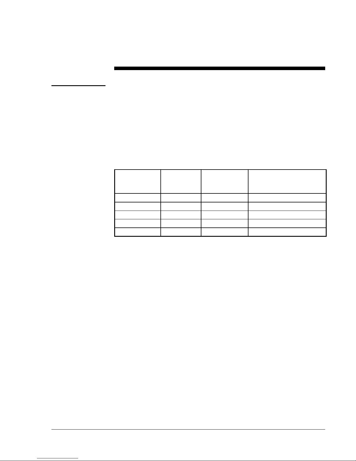
Table 1: Selection Table--Actuators and Linkages
Linkage
Number
Y20EBD-1
Y20EBD-2
Y20EBD-3
Y20EBD-5
Y20EBD-6
Spring
Return
Actuator
M130 M120 75 (334) Green
--- M140 150 (607) Yellow
--- M150 270 (1201) Red
M110 --- 40 (178) Orange
M130 M120 100 (449)
Non-spring
Return
Actuator
Valve Seating Load, lb (n)
Note: The Y20EBD linkage kit can be used on Barber-Colman
1-1/2 to 2 inch valves. Use the grooved adapter bushing provided
with the linkage kit for V-90 Series and the mid-bracket position.
Larger Barber-Colman valves can mount onto the Y20EBD yoke
directly; however, adding locally purchased large washers under
the linkage bracket to prevent paint damage is recommended.
A selection of models are available to adapt M100 Motor Actuators to
several types of valves.
A Y20EBD-4 linkage is available to enable an M150 Motor Actuator to
operate S91 auxiliary switches for automatic heating/cooling changeover
applications. The Y20EBD-4 allows additional over travel after valve
close off for switch operation. See Y20 Series Linkage Kits Product
Bulletin for a complete description.
Y20EBA valve linkage kits are available to adapt the M100 Series
Actuators to valves made by other manufacturers. See Y20 Series Linkage
Kits Product Bulletin for more information.
Refer to the technical bulletin provided with the motor actuator for
information on wiring the motor actuator and related adjustments.
M Motor Actuators
Y20EBD Valve Linkage for M100 Motor Actuators 3
—
Page 4

Glossary
The following terminology is used in these instructions:
CW--Clockwise refers to the direction of rotation of the actuator shaft as
seen from the load end.
Zero Position--The fully counterclockwise position of the actuator
shaft--the de-energized position of a spring return actuator.
Stem Up--The initial position of the stem is up before operating the valve.
Stem Down--The initial position of the stem is down before operating the
valve.
Push/Drive Down to Open--Pushing or driving the stem down opens
the valve.
Push/Drive Down to Close--Pushing or driving the stem down closes
the valve.
Pull/Drive Up to Open--Pulling or driving the stem up opens the valve.
Pull/Drive Up to Close--Pulling or driving the stem up closes the valve.
Stem Up/Drive Down--The stem is initially in the up position and the
motor actuator through the linkage will drive the stem down.
Stem Down/Drive Up--The stem is initially in the down position and the
motor actuator through the linkage will drive the stem up.
Three Way Mixing Valve--A valve with two inlets and one outlet. Valve
seats on both stem up and stem down travel.
Three Way Diverting Valve--A valve with one inlet and two outlets.
Valve seats on both stem up and stem down travel.
4 M Motor Actuators
Y20EBD Valve Linkage for M100 Motor Actuators
—
Page 5
Installation Procedures
Tools Needed
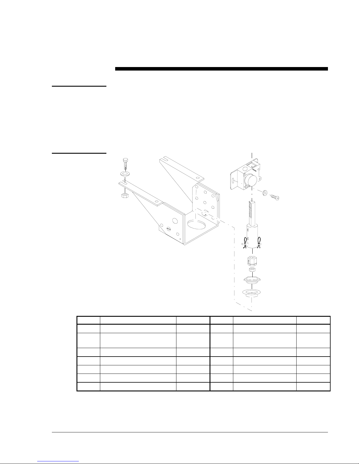
Kit Includes
• screwdriver, small blade
• screwdriver, medium blade
• pliers
• wrench, adjustable, medium
• socket wrench, 3/8 inch drive
7
8
9
1
Y20D1-01
12
13
14
11
10
5/6
4
2/3
Item Description Quantity Item Description Quantity
Mounting Bracket Assembly 1
1
Valve Bushing, 3/4 in. Not
2
Grooved
Valve Bushing, 1 in. Grooved 1
3
Yoke Nut 1
4
Hex (Jam) Nut, 1/4-28 1
5
Hex (Jam) Nut, 3/8-20 1
6
Hex Cap Screw 4
7
1
Washer (High Temp) 4
8
Hex Nut, 1/4-20 4
9
Valve Stem Connector 1
10
Rack Subassembly 1
11
Gear Subassembly 1
12
Washer, Black 2
13
Screw 2
14
Figure 1: Kit Components
M Motor Actuators
Y20EBD Valve Linkage for M100 Motor Actuators 5
—
Page 6

Installation
Overview
Upright mounting of the motor actuator is recommended.
When valve mounting, do not mount below the horizontal plane of the
valve piping to prevent damage to the motor actuator if the valve leaks or
develops condensation.
Do not install the motor actuator in atmospheres with explosive vapors or
escaping gases, or where vapors having deteriorating properties might
attack the actuator’s metal parts.
Do not install where the ambient temperature of the surrounding area falls
below -40°F (-40°C) for non-spring return motor actuators, or
-35°F (-37°C) for spring return motor actuators. The maximum ambient
temperature of the surrounding area of the motor actuator should not
exceed 125°F (52°C).
Valve medium temperatures above 250°F (121°C) are permissible only if
the maximum ambient temperature at the motor actuator is less than 105°F
(41°C).
Use insulating washers furnished with the linkage kit for valve medium
temperature applications over 250°F (121°C).
Locate the motor actuator where the shaft and wiring terminals are
accessible.
The non-spring return M100 Actuator will hold its position if power is
removed. The spring return actuator will return to its zero position if
power is removed. Both types will hold their current position if the
control signal is satisfied.
Note: The spring return is intended only as a safety feature to drive the
actuator to its zero position in the event power is interrupted or
turned off.
There are three sections to the installation of the Y20EBD valve linkage
kit:
1. Configure and mount the yoke on the valve.
2. Mount the actuator and linkage assembly to the yoke and connect to
the valve.
3. Adjust the travel limits to actuate the over travel spring and seat the
valve.
6 M Motor Actuators
Y20EBD Valve Linkage for M100 Motor Actuators
—
Page 7
Configuration
and Mounting
Valve Lift
The information obtained in the following steps will be used for the travel
adjustments later. The reason that these measurements are here is that it is
easier to take the measurements prior to installing the linkage and actuator
than after.
For valves with various lift requirements, the actuator will require a
change in travel by 15° for each additional 0.1 inch (2.54 mm) of lift
required.
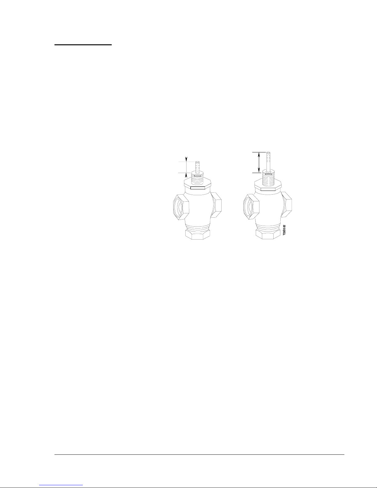
To determine the lift required:
Valve Stem
Full Down
Valve Stem
Full Up
Figure 2: Stem Travel Measurement
1. Measure the valve stem length in the full down position as shown in
Figure 2.
2. Measure the valve stem length in the full up position as shown in
Figure 2.
3. Subtract the full down position from the full up position, this will
provide the valve lift.
4. Divide the valve lift by 0.1 inch.
5. Multiply the result by 15°.
6. Provide additional 15° rotation on 2-way valves and 30° additional
rotation on 3-way valves for over travel seating.
Note: Maximum actuator rotation is 270°, which allows up to 1.7 inches
lift on 2-way valves and 1.6 inches lift on 3-way valves.
Note: VT valves have only 5/16 inch lift which requires a reduction of
actuator travel by 25° from factory setting.
Record the value for use with the travel adjustments.
M Motor Actuators
Y20EBD Valve Linkage for M100 Motor Actuators 7
—
Page 8
Configuring Yoke
When configuring the yoke, two areas have to be considered:
• the distance the actuator will be from the valve (height)
• the direction of drive the actuator is going to provide to the valve
Height
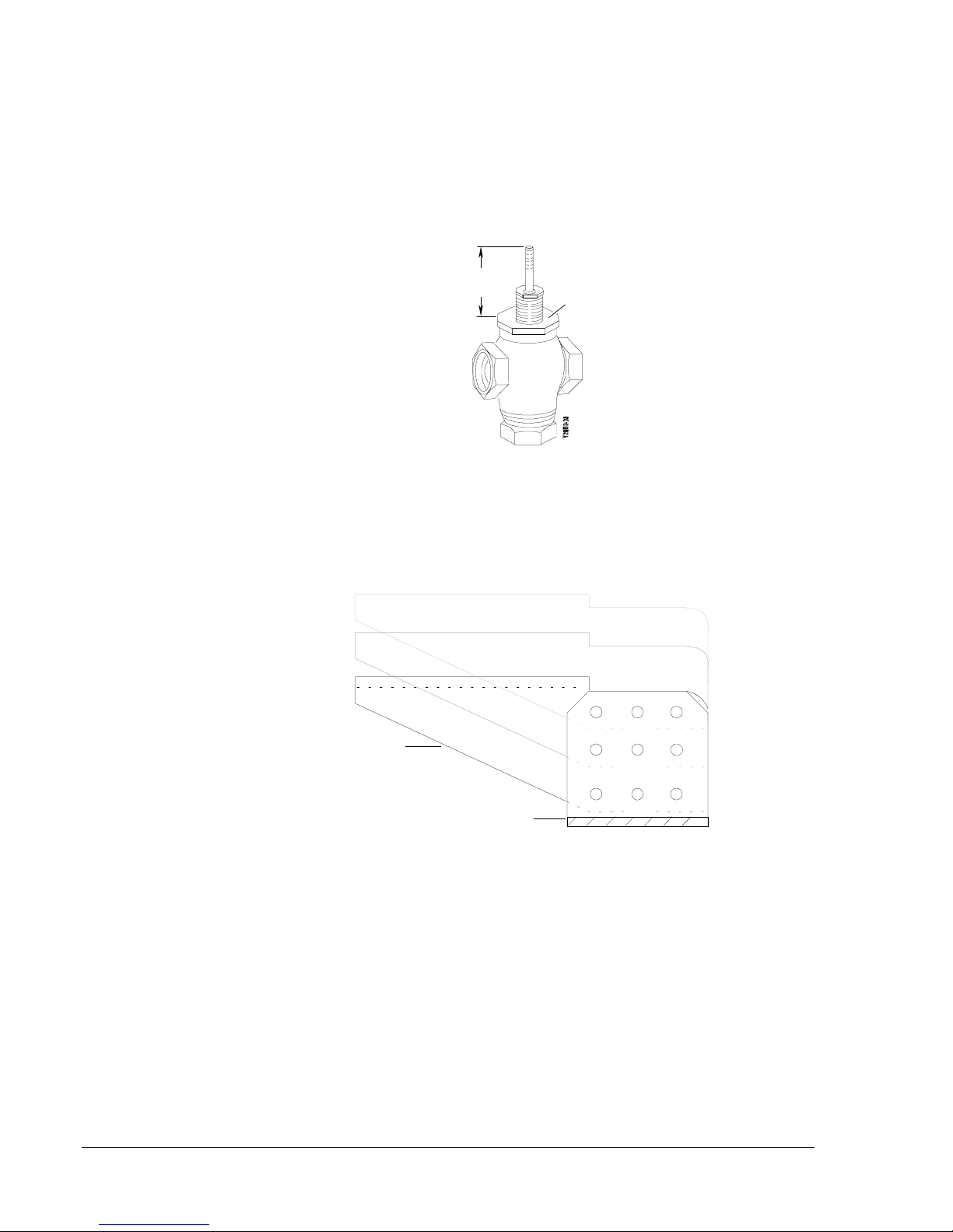
To determine the height:
Valve Stem
Full Up
Valve Stem
Full Up
Yoke
Mounting
Surface
Figure 3: Height Measurement
1. Raise the valve stem to its full up position.
2. Measure from the yoke mounting surface to the top of the stem.
8 M Motor Actuators
High
Brackets
Medium
Y20A1-04
Yoke
Low
Figure 4: Linkage Bracket Positions
The linkage brackets can be mounted to the yoke in one of three positions:
low, medium, or high.
• Low position for stem lengths from 2 inches up to 3 inches
(50.8 to 76.2 mm) in full up position. Johnson brass valves up to
2 inch (50.8 mm) pipe size.
• Medium position for stem lengths from 3 inches to 4 inches
(76.2 to 101.6 mm) in full up position. Johnson iron valves from
2-1/2 inches (63.5 mm) pipe size and larger. V90BA valves up to
2 inch (50.8 mm) and V90CA valves up to 3 inch (76.2 mm) pipe
sizes.
Y20EBD Valve Linkage for M100 Motor Actuators
—
Page 9

• High position for stem lengths from 4 inches to 5-7/8 inches
(101.6 to 147.2 mm) in full up position. V90CA valves from 4 inch
through 6 inch (101.6 through 152.4 mm) pipe sizes.
LOAD ENDLOAD END
Y20A1-05
Figure 5: Long and Short Stem Valve Bodies
The left side of Figure 5 shows a Y20EBD Valve Linkage in the high
position connecting a 3-way valve body with a long stem to a M100 Motor
Actuator for stem up operation.
Direction
The right side of Figure 5 shows a Y20EBD Valve Linkage in the low
position connecting a 2-way valve body with a short stem to a M100
Motor Actuator for stem up operation.
Except for M100C (reverse acting) and M100H models, with an increasing
signal, the actuator always operates Clockwise (CW) from its zero
mechanical position. This clockwise rotation can be used to drive the
valve stem up or down, depending on the way the gear housing is attached
to the actuator.
To determine the direction of actuator drive:
Direction of
Drive Rotation
LOAD END
Y20D1- 06
Figure 6: Motor Actuator and Valve
M Motor Actuators
Y20EBD Valve Linkage for M100 Motor Actuators 9
—
Page 10

1. With the motor actuator next to the valve, view the motor actuator
from the load end.
2. Determine the type of valve being used and the direction that will be
required to drive the stem from its initial position.
• Stem Up Two Way Valve--Drive Down to Close
• Stem Up Two Way Valve--Drive Down to Open
• Stem Down Two Way Valve--Drive Up to Open
• Stem Down Two Way Valve--Drive Up to Close
• Stem Up Three Way Valve
• Stem Down Three Way Valve
Changing Yoke
Load End
Y20A1-07
Load End
Figure 7: Stem Up/Drive Down and Stem Down/Drive Up
3. For valves with the stem in the initial up position, the hole in the yoke
will be to the right of center when facing the load end as shown in the
left illustration of Figure 7.
For valves with the stem in the initial down position, the hole in the
yoke will be to the left of center when facing the load end as shown in
the right illustration of Figure 7.
The brackets are assembled at the factory in the low position and for stem
up/drive down valve application with the hole in the yoke to the right of
center as shown in the left illustration of Figure 7.
For any other application, the yoke and brackets must be disassembled and
reassembled for the specific application as described below.
10 M Motor Actuators
Y20EBD Valve Linkage for M100 Motor Actuators
—
Left Side
Bracket
Yoke
Screw
Washer/
Nut
Figure 8: Bracket Components
Right Side
Bracket
Y20D1-O8
Page 11

1. Remove the screw, washer, and nut securing the left and right side
brackets to the base bracket.
2. Position the yoke, left side, and right side brackets as determined
previously. The pins on the side brackets will fit into the holes in the
yoke until the screw is inserted.
3. Install the screw, washer, and nut to secure the side brackets to the
yoke and tighten.
Mounting Yoke
Note: The Y20EBD Linkage Kit can be used on Barber-Colman 1-1/2 to
2 inch valves. Use the grooved adapter bushing provided with the
linkage kit for V-90 Series and the mid-bracket position. Larger
Barber-Colman valves can mount onto the Y20EBD yoke directly;
however, adding locally purchased large washers under the linkage
bracket to prevent paint damage is recommended.
To mount the yoke on the valve:
Yoke Nut
Packing Nut
Spring P late
Valve
Y20D1-09
Figure 9: Preparing Valve
1. Remove the yoke nut (if present), packing nut (if necessary), and
spring plate (if present) from the valve as shown in Figure 9.
Note: Valves with 1/4 inch stems use the furnished yoke nut having a
3/4 inch thread to install the bushing and secure the bracket.
Larger valves have a one inch packing box thread on the yoke
which fits the smaller hole bushing and requires a separate yoke
nut that is usually furnished with the valve.
M Motor Actuators
Y20EBD Valve Linkage for M100 Motor Actuators 11
—
Page 12

Jam Nu t
Packing Nu t
Yoke Nut
Bushing
Valve
Y20D1- 10
Figure 10: Mounting Yoke
2. Place the yoke on the valve over the stem and bonnet.
3. Select the proper bushing and slide it over the bonnet and into the
yoke hole.
1.078
27.38
Y20D1- 11
1.015
25.78
Figure 11: Bushings
Note: Two bushings are provided:
• large hole--1.078 in. (27.38 mm) inside diameter which is
identified by a smooth outer edge
• small hole--1.015 inch (25.78 mm) inside diameter which is
identified by a groove on its outer edge
In general, valves up to two inch pipe size have 1/4 inch stems and use
the large hole (no groove) bushing; valves larger than two inch pipe
size have 3/8 inch stems and use the small hole bushing (with groove).
4. Install the yoke nut. For valve bodies 2-1/2 inch and larger, use the
yoke nut furnished with the valve. Fasten the yoke in place securely
by tightening the yoke nut with a wrench 1/8 turn past finger tight.
5. If the packing nut was removed, reinstall and tighten it. For valves
with U-Cup packing, tighten the nut 1/8 turn past “finger tight.” For
all other valves, tighten finger tight.
Note: JCI valves have U-Cup packing.
12 M Motor Actuators
Y20EBD Valve Linkage for M100 Motor Actuators
—
Page 13

6. Install the proper size jam nut onto the valve stem as far as it will go.
Do not tighten.
M Motor Actuators
Y20EBD Valve Linkage for M100 Motor Actuators 13
—
Page 14

Actuator and
Linkage
Mounting
Actuator
M100
Motor
Actuator
Hex Capscrew
High
Temp erature
Washer
Nut
Y20D1- 12
Figure 12: Mounting Motor Actuator
1. Locate the load end over the yoke.
2. Mount the actuator onto the brackets using the four bolts and nuts, but
do not tighten.
Note: If the temperature of the valve or its media is high enough to raise
the actuator temperature above its limit of 125°F (52°C), insert the
four white insulating washers (provided with the linkage kit)
between the actuator and the brackets. For lower temperature
applications, omit the insulating washers.
14 M Motor Actuators
Y20EBD Valve Linkage for M100 Motor Actuators
—
Page 15

Valve Stem
Connector
As received, the valve stem connector (mounted in the spring housing of
the rack subassembly) accommodates a 1/4 inch stem valve. If the valve
has a 3/8 inch stem, replace the connector with the 3/8 inch connector
furnished separately. To change the valve stem connector:
Spring
Housing
Mounting
Linkage
Pin
Y20A1-11
Spring Clip
Valve Stem
Connector
Figure 13: Valve Stem Connector
1. Remove the spring clip and pin from the spring housing as shown in
Figure 13.
2. Insert the connector nut so that the holes line up with the holes in the
spring housing.
3. Replace the pin and spring clip.
Note: It is a good idea to verify which valve stem connector is inserted
prior to installation.
To mount the gear housing and rack assembly to the motor actuator and
valve, proceed as follows:
Hole for
Rack Subassembly
1. Loosen the two gear cover screws and remove the gear cover and gear
Gear
Housing
Y20A1-12
Gear
Gear
Cover
Gear Cover
Screws
Figure 14: Gear Housing Assembly
from the gear housing as shown in Figure 14.
M Motor Actuators
Y20EBD Valve Linkage for M100 Motor Actuators 15
—
Page 16

2. Determine the required position of the gear housing on the load end of
the actuator so that the opening for the rack assembly is located as
follows:
• stem up position, drive down operation--rack to the right
• stem down position, drive up operation--rack to the left
Housing
Lockin g Sc re w
Rack
Subassembly
Y20A1-13
Figure 15: Inserting Rack Subassembly
3. Insert the rack subassembly into the gear housing by sliding it from
the bottom through the hole in the gear housing as shown in Figure
15.
Note: If the rack subassembly has difficulty being inserted, check the
locking screw to make sure that it is not interfering with movement
of the rack. If it is, back it out until there is no interference.
4. When the rack subassembly is completely in the housing, tighten the
locking screw to secure the rack subassembly in position.
Washers
Screws
Rack Subassembly
Spring Housing
Jam Nu t
16 M Motor Actuators
Y20EBD Valve Linkage for M100 Motor Actuators
—
Y20D1-15
Figure 16: Mounting Gear Housing
Page 17

Travel Limits
5. Position the gear housing and rack subassembly over the valve stem
and align the gear housing with the M100 drive shaft.
6. Attach the gear housing to the motor actuator with the washers and
gear housing screws. Do not tighten the screws at this time.
7. Loosen the locking screw and lower the rack subassembly to the
valve stem. Thread the rack subassembly spring housing completely
onto the valve stem.
8. Tighten the jam nut (shown in Figure 16) against the stem connector.
9. Align the actuator with the valve body to avoid binding of the linkage
and tighten the four mounting bolts.
10. Tighten the screws securing the gear housing to 25 in·lb (2.83 N·m)
maximum.
!
CAUTION: Do not perform the following operations if the valve is
under pressure. Shut off pump power, including
standby power, before attempting manual operation.
The procedure for adjusting the travel limits is different for the different
configurations of valves:
• Stem Up Two Way Valve--Drive Down to Close Drive down to close,
spring return open is the most common configuration for heating.
• Stem Up Two Way Valve--Drive Down to Open
• Stem Down Two Way Valve--Drive Up to Open
• Stem Down Two Way Valve--Drive Up to Close
• Stem Up Three Way Valve
• Stem Down Three Way Valve
!
CAUTION: Travel adjustments are made with power connected to
the actuator. On M100A Actuators, always
disconnect power from the actuator before adjusting
the slide stop to increase travel.
M Motor Actuators
Y20EBD Valve Linkage for M100 Motor Actuators 17
—
Page 18

Direction of Drive
Rotation COM
to CW Shorted
Keywa y
Direction of
Drive Rotation
COM to CCW Shorted
LOAD END
10° (AX)
Zero Reference
Positi o n
Drive Shaft
Y20A1-15
Figure 17: Actuator Zero Position
The actuators are factory set at zero position which is 10° clockwise from
square and for 90° clockwise travel as shown in Figure 17. Each 15° of
actuator rotation results in 0.1 inch (2.54 mm) of linear movement of the
rack assembly. The 90° actuator rotation provides 1/2 inch (12.7 mm) of
valve stem lift plus 0.1 inch (2.54 mm) of over travel.
Disconnect all control wires to the actuator. Refer to the technical bulletin
provided with the motor actuator for information on wiring the motor
actuator and related adjustments.
Connect only 24 VAC to terminals T1-T2. Be sure that power is off while
connections are made or changed. For quick reference, Table 2 provides
the connections for individual actuators.
Stem Up Two
Way Valve
Note: The M100C requires a Y199 tester to drive the motor actuator.
For stem up valves, make certain that the rack is assembled to the right of
the gear housing center.
Drive Down to Close Valves
1. Manually move the rack and spring housing assembly, connected to
the valve stem, to the full up position.
Y20A1-16
Figure 18: Pinion Gear Ends
2. Insert the pinion gear into the gear housing with the square hole end
(Figure 18) over the actuator shaft.
3. Replace the gear cover and tighten the gear cover screws. See
Figure 14.
18 M Motor Actuators
Y20EBD Valve Linkage for M100 Motor Actuators
—
Page 19

4. Refer to the technical bulletin provided with the motor actuator and
adjust the actuator travel to drive the stem down and compress the
spring in the housing (turn power off when adjusting M100A slide
stops).
Actuator
Drive
Upper
Visual
Guide
Lower
Visual
Guide
Flat
Washers
Figure 19: Upper Visual Guide Indicating Full Down Travel
5. As shown in Figure 19, when the edge of the upper flat washer is
opposite the notch in the upper visual guide, the travel is properly
adjusted. This represents 0.1 inch (2.54 mm) compression of the
spring with the valve seated.
Drive Down to Op en V alv es
1. Power the actuator to position the actuator 15° from zero. This is
equivalent to 0.1 inch (2.54 mm) of stem travel.
2. Manually move the rack and spring housing assembly, connected to
the valve stem, to the full up position.
3. Insert the pinion gear into the gear housing with the square hole over
the actuator shaft.
4. Replace the gear cover and tighten the gear cover screws.
5. Allow the actuator to return to zero position.
Actuator
Drive
Upper
Visual
Guide
Lower
Visual
Guide
Flat
Washers
M Motor Actuators
Y20EBD Valve Linkage for M100 Motor Actuators 19
—
Page 20

Figure 20: Lower Visual Guide Indicating Full Up Travel
6. As shown in Figure 20, the edge of the lower flat washer should
appear opposite the notch in the lower visual indicator to indicate
compression of the spring with the valve seated.
7. Refer to the technical bulletin provided with the motor actuator and
adjust the actuator travel for the full lift as described in the Valve Lift
section.
Stem Down Two
Way Valves
For stem down valves, make certain that the rack is assembled to the left
of the gear housing.
Drive Up to Close Valves
1. Manually move the rack and spring housing assembly, connected to
the valve stem, to the full down position.
2. Insert the pinion gear into the gear housing with the square hole over
the actuator shaft.
3. Replace the gear cover and tighten the gear cover screws.
4. Refer to the technical bulletin provided with the motor actuator and
adjust the actuator travel to drive the stem up and compress the spring
in the housing (turn power off when adjusting the M100A slide stop).
5. When the edge of the lower flat washer is opposite the notch in the
lower visual guide, the travel is properly adjusted. This represents
0.1 inch (2.54 mm) compression of the spring with the valve seated.
Drive Up to Open Valves
1. Power the actuator to position the actuator 15° from zero. This is
equivalent to 0.1 inch (2.54 mm) of stem travel.
2. Hold the rack in its full down position.
3. Insert the pinion gear into the gear housing with the square hole over
the actuator shaft.
4. Replace the gear cover and tighten the gear cover screws.
5. Allow the actuator to return to zero position. The edge of the upper
flat washer should appear opposite the notch in the upper visual
indicator to indicate compression of the spring with the valve seated.
6. Refer to the technical bulletin provided with the motor actuator and
adjust the actuator travel for full lift as described in the Valve Lift
section.
20 M Motor Actuators
Y20EBD Valve Linkage for M100 Motor Actuators
—
Page 21

Three Way Valves
Three way valves, mixing or diverting, can be assembled so that the upper
seat is initially closed (stem up) or so that the lower seat is initially closed
(stem down). Stem up or stem down operation is determined by the yoke
configuration and position of the rack and gear housing. Travel
adjustments are similar for either case and require both upper and lower
limits to be set. Both mixing and diverting 3-way valves are adjusted the
same way.
1. Power the actuator to position the drive shaft 15° from zero. This is
equivalent to 0.1 inch of stem travel.
2. Manually position the rack to the full stem up or stem down position
as required.
3. Insert the pinion gear into the gear housing with the square hole over
the actuator shaft.
4. Replace the gear cover and screws.
. . . .
. . . .
. . . .
. . . .
Modulating Lower Seat Closed Upper Seat Closed
Upper
Visual Guide
For Lower
Seat Close Off
Upper Valve Seat
(3-way Valves)
Valve Plug
Lower Valve
Seat (2- wa y an d
3-way Valves)
. . . .
. . . .
. . . .
. . . .
Lower
Visual Guide
For Upper
Seat Close Off
. . . .
. . . .
. . . .
. . . .
Figure 21: Linkage Adjustment Stem Up 3-Way Valve
5. Allow the actuator to return to the zero position. The flat washer
should align with the notch at the bottom of the spring case for stem
up valves or with the upper notch for stem down valves. This
indicates valve seating at the zero position.
6. Refer to the technical bulletin provided with the motor actuator and
adjust the travel to fully stroke the valve and compress the over travel
spring at full lift. The washer should be aligned with the notch
opposite the starting point.
7. Figure 21 illustrates the over travel indication for seating stem up
3-way valves.
M Motor Actuators
Y20EBD Valve Linkage for M100 Motor Actuators 21
—
Page 22

Manual Operation
!
CAUTION: Do not perform this operation if the valve is under
pressure. Shut off pump power, including standby
power, before attempting manual operation.
The valve can be manually operated without electrical power when
necessary for maintenance or emergency operation. To operate the valve
manually:
1. Remove the gear cover.
2. Remove the pinion gear from the gear housing and insert the gear
with the square hole facing out.
3. A 3/8 inch socket wrench drive will fit in the square hole and enable
manual positioning of the valve.
4. The spring can be compressed and then held in position by turning the
locking screw (located on the gear housing) in to hold the rack in
position.
IMPORTANT: To return to automatic operation, return the actuator to
the zero position and reinstall the gear with the square
hole engaging the actuator shaft. Repeat the travel limit
adjustments as necessary.
22 M Motor Actuators
Y20EBD Valve Linkage for M100 Motor Actuators
—
Page 23

Checkout Procedure
After Installation and adjustment, run the system through several complete
open/close cycles to be sure that all components are functioning correctly.
Check to be sure that the actuator responds to the controller and operates
the valve properly. Check for proper voltage. Check for operation of the
linkage without binding.
!
CAUTION: The actuator should not be stalled by the valve. The
actuator may be damaged if it is not free to complete
its full stroke.
Table 2: Actuator Connections for Travel Limit Adjustment
Jumper Terminals
Model Clockwise (CW) Counterclockwise (CCW)
M100A
M100C
M100E
M100F
M100G or M100H
M100J
M100Q
M100M
Apply 24 VAC to relay terminals A and C for clockwise rotation.
*
1 and 2 1 and 3
COM to CW COM to CCW
S1 to S2* Disconnect S1, S2, A, C
8 and 9 8 and 10
8 to T1 8 to 10
8 and 9 8 and 10
8 to T1 8 to 10
R to B Disconnect R from B
Note: On all models, remove controller wires and apply 24 VAC to
terminals T1 and T2 while making adjustments. Spring return
models will go full CCW when power to T1 and T2 is removed.
M Motor Actuators
Y20EBD Valve Linkage for M100 Motor Actuators 23
—
Page 24

Replacement Parts
Table 3 shows replacement parts that may be ordered from your nearest
Johnson Controls branch or distributor.
Table 3: Y20 Linkage Repair Parts
Description Code Number Remarks
Gear Assembly
Gear Only
Gear Cover
Spring Housing
and Rack
Assembly *
* Rack and Spring Housing are an assembly with spring and standard connector (1/4-28)
installed.
Specify Spring Load for application when ordering.
GER18A-600 Includes CVR115-1 and GER28-1
GER28-1
CVR115-1 Includes Mounting Screws
RCK12A--620
RCK12A--621
RCK12A--622
RCK12A--623
RCK12A--624
RCK12A--626
270 lb (1201 N) -- used with Y20EBD-3
179 lb (796 N) -- used with Y20EBD-4
150 lb (667 N) -- used with Y20EBD-2
75 lb (334 N) -- used with Y20EBD-1
40 lb (178 N) -- used with Y20EBD-5
100 lb (445 N) -- used with Y20EBD-6
Table 4: Accessories
Description Part Number
5/16 inch Stem Connector
VT Adapter Kit
Y20EBE-1
Y20EBE-2
24 M Motor Actuators
Y20EBD Valve Linkage for M100 Motor Actuators
—
Page 25

Notes
Controls Group
507 E. Michigan Street
P.O. Box 423 Printed in U.S.A.
Milwaukee, WI 53201
M Motor Actuators
Y20EBD Valve Linkage for M100 Motor Actuators 25
—
 Loading...