

Page 1

WT-ROUTER Router
24- 10732- 13, Rev. B
Installation Instructions
WT-ROUTER
Part No. 24-10732-13, Rev. B
Issued August 2017
Refer to the QuickLIT website for the most up-to-date version of this document.
Application
The WT-ROUTER Router relays wireless
transmissions from a Johnson Controls® WT-4000
Series Pneumatic-to-Direct Digital Control (DDC)
Room Thermostat to other WT-ROUTER Routers or
to a Johnson Controls WT-BAC-IP Gateway. Adding
routers to a wireless mesh network enhances the
robustness of the network by extending the wireless
mesh communication range up to 750 ft (229 m).
In addition, the routers provide multiple routes of
communication with the gateway.
The WT-ROUTER Router installs in minutes with no
need to run network cables. An STS LED indicator
(Figure 1) allows for strategic positioning in areas with
reliable network connectivity. The router is powered by
a low-voltage 5 to 30 VDC power supply.
The WT-ROUTER Router is de signed for indoor,
intra-building applications only. The router uses
direct-sequence, spread-spectrum RF technology,
and operates on the 2.4 GHz Industrial, Scientific,
and Medical (ISM) band. The router also meets the
IEEE 802.15.4 standard for low power, low duty cycle
RF transmitting systems.
IMPORTANT: Use the WT-ROUTER Router only to
provide an input to equipment under normal
operating conditions. Where failure or malfunction of
the router could lead to personal injury or property
damage to the controlled equipment or other
property, additional precautions must be designed
into the control system. Incorporate and maintain
other devices, such as supervisory or alarm systems
or safety or limit controls, intended to warn of or
protect against failure or malfunction of the router.
North American Emissions Compliance
United States
Compliance Statement (Part 15.19)
This device complies with Part 15 of the FCC Rules.
Operation is subject to the following two conditions:
1. This device may not cause harmful interference,
and
2. This device must accept any interference
received, including interference that may cause
undesired operation.
Warning (Part 15 .21)
Changes or modifications not expressly approved by
the party responsible for compliance could void the
user’s authority to operate the equipment.
Canada
Industry Canada Statement
The term IC before the certification/registration
number only signifies that the Industry Canada
technical specifications were met.
Le terme « IC » précédant le numéro d'accréditation/
inscription signifie simplement que le produit est
conforme aux spécifications techniques d'Industry
Canada.
WT-ROUTER Router Installation Instructions 1
Page 2
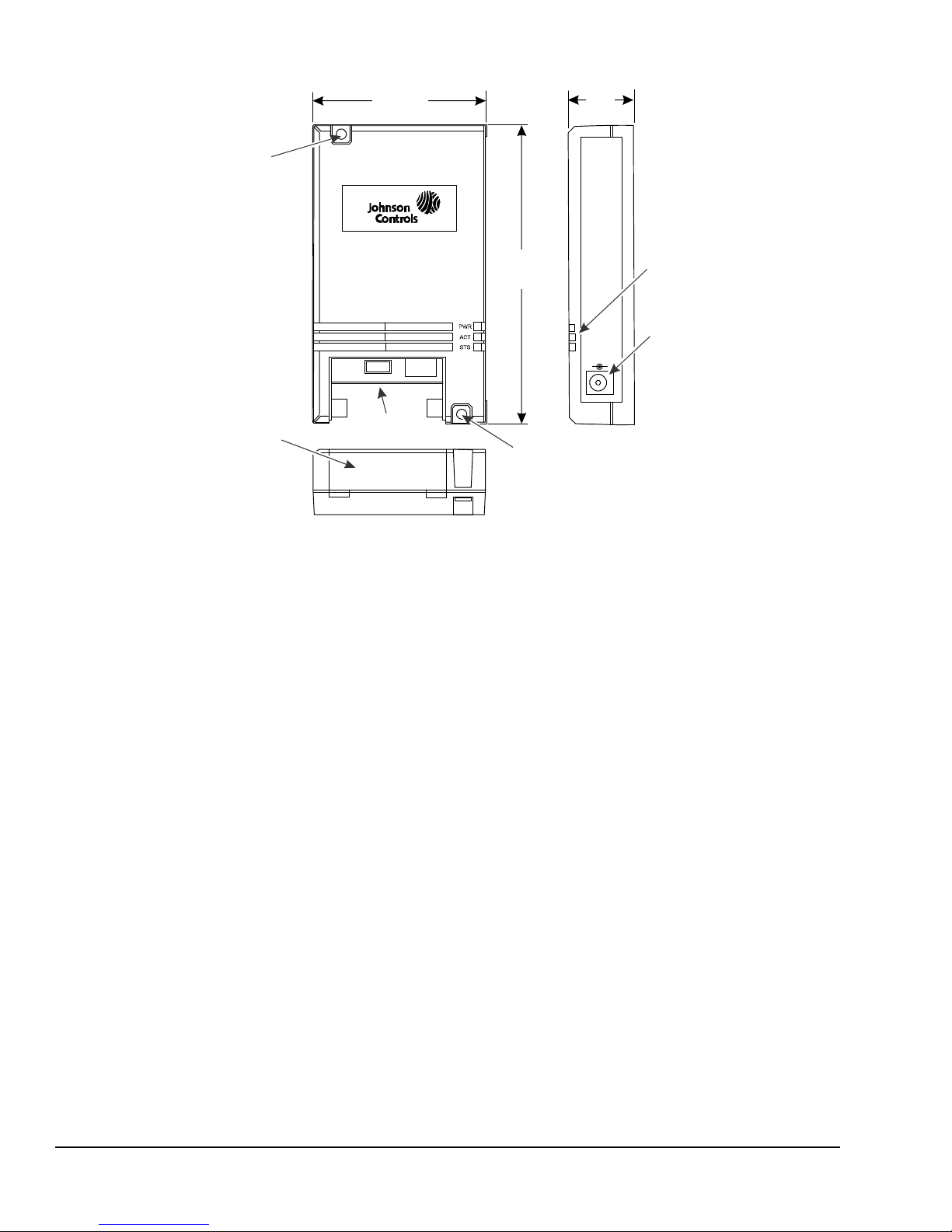
Figure 1: WT-ROUTER Router
Physical Features and Dimensions, in. (mm)
OFF/ON
(118)
1
(25)
FIG:wt_rtr
2-23/32
(69)
LED
Connector Panel
Access Cover
Mounting Hole
(Tw o Locations)
OFF/ON
Switch
Mounting Hole
Power
WT -Router
Status Indication LEDs
The WT-ROUTER communicates status using the
following LEDs:
• STS LED—Blinking indicates that the router is
• ACT LED—On steady indicates that there is RF
• PWR LED—On steady indicates that power is
Installation
Follow these guidelines when installing the
WT-ROUTER Router:
• Transport the router in the original container to
• Verify that all the parts shipped with the router.
• Do not drop the router or subject it to physical
• Do not attempt to open the router housing or repa ir
connected to the wireless network with only one
active path. This LED remains on if two or more
wireless paths exist.
traffic at the device.
applied to the device.
minimize vibration and shock damage.
shock.
the device; the router is not user serviceable.
PROGRAM
4-21/32
(Tw o Location s)
Indicators
Connector
Parts Included
• one WT-ROUTER Router
• one power adaptor
• one installation instructions sheet
Mounting
The WT-ROUTER Router can be surface mounted
using two field-furnished screws. Mount the unit to the
surface at the two mounting hole location s on the
device (Figure 1).
The router can also be secured to a bracket above a
drop ceiling using field-furnished tie wraps.
Location Considerations
The WT-ROUTER Router must remain powered up at
all times to operate properly. Choose an installation
location where the power supply cannot be accidentally
unplugged. An ideal location for the rout er is abov e a
drop ceiling with a dedicated power source.
WT-ROUTER Router Installation Instructions2
Page 3

To determine if routers are required in a mesh network
Figure 2: White Sticker on Back of Router
Showing Location of Group ID
installation, check the network status of all the
WT-4000 Series Room Thermostats in the network. If
the signal strength indicator shows good network
communication with the WT-BAC-IP Gateway, then no
routers are required. If the signal strength indicator
shows poor network communication with the gateway,
then routers are required to extend the range of
transmissions up to 750 ft (229 m). Try to position the
router somewhere between the devices that are offline
and the devices connected to the network.
Note: Avoid installing the router near equipment that
may interfere with the 2.4 GHz RF signal, such as
cordless telephones or Wi-Fi access points that
operate on the 2.4 GHz ISM band.
2. Document the device ID and location of each
router on the floor plan prior to installation. The
device ID sticker is located on the back of the
router.
Note: You may opera te the router while it is resting on
a desktop or mounted to a wall. If the router is mounted
to a wall, be sure to secure it in place using the
appropriate fasteners (field furnished).
3. Plug the power adaptor (included with the router)
into a 110/120 VAC outlet, then plug the power jack
on the power supply cable into the power
connector on the side of the router (Figure 1).
4. If the PWR LED indicator is not green, remove
the connector panel access cover and slide the
OFF/ON switch to the ON position (Figure 1).
5. Reinstall the connector panel access cover.
6. Confirm that the STS LED on the router (Figure 1)
and the signal strength indicator on the WT-4000
Series Room Thermostat indicate good wireless
communication between the devices.
In order for the devices to connect to the same mesh
network, they all must have the same Group ID. The
Group ID is set at the factory and cannot be changed in
the field. Figure 2 illustrates the white sticker on the
back of the router that shows the location of the
Group ID.
Installing the WT-ROUTER Router
To install the WT-ROUTER Router:
1. Position the router in an indoor location with good
wireless reception. Verify that the router is within
100 to 250 ft (30 to 76 m) of the other devices in
the mesh network.
Repair Information
If the WT-ROUTER Router fails to operate within its
specifications, replace the unit. For a replacement
router, contact the nearest Johnson Controls
representative.
WT-ROUTER Router Installation Instructions 3
Page 4

Table 1: WT-ROUTER BACnet Object List (for WT-BAC-IP 1.3.5)
Register
Number
Point Name Description BACnet
Object
Type
201 Hop_Count The number of hops through which the device’s data is routed to reach the
MeshGate; 65535 indicates that the device is offline.
202 1st_Hop_ID_H High byte of the device ID of the first hop node. AI
1st_Hop_ID_L Low byte of the device ID of the first hop node. AI
204 RSSI High byte indicates radio received signal strength (RSSI) (signed 8 bit for
Modbus register; BACnet object shows actual value).
Batt_Voltage Low byte indicates the battery voltage level in VDC multiplied by 10 (BACnet
object shows actual value).
224 RF_Channel Radio channel number used by the device. AV
510 Dev_Type The integer value that identifies the device type in the wireless network; for use
by the MeshGate, not customer applications.
AI
AI
AI
AI
Technical Specifications
WT -ROU TER Router
Power Requirements External DC Supply: 5 to 30 VDC from the power adaptor (included with the router)
Minimum Supply Voltage: 3.1 VDC
Wireless Band Direct-sequence, spread-spectrum, 2.4 GHz ISM band
Operating Frequency Range 2,405 to 2,475 MHz
Channels Quantity: 15
Spacing: 5 MHz
Transmissions Power: 18 dBm maximum
Rate: 250 Kbits per second
Ambient Conditions Operating: 14 to 131°F (-10 to 55°C), 5 to 95% RH, noncondensing
Storage:
Materials Gray ABS plastic housing
Compliance United States:
Transmission Complies with FCC Part 15.247 Regulations for Low Power Unlicensed
Transmitters
Transmitter FCC Identification: HSW-Z2430HPA
RoHS compliant (EU Directive)
Canada:
Industry Canada IC: 4492A-Z2430HPA
Shipping Weight 0.41 lb (0.19 kg)
-40 to 185°F (-40 to 85°C), 5 to 95% RH, noncondensing
The performance specifications are nominal and conform to acceptable industry standard. For application at conditions beyond these
specifications, consult the local Johnson Controls office. Johnson Controls shall not be liable for damages resulting from misapplication or
misuse of its products.
European Single Point of Contact: NA/SA Single Point of Contact: APAC Single Point of Contact:
JOHNSON CONTROLS
WESTENDHOF 3
45143 ESSEN
GERMANY
JOHNSON CONTROLS
507 E MICHIGAN ST
MILWAUKEE WI 53202
USA
WT-ROUTER Router Installation Instructions4
JOHNSON CONTROLS
C/O CONTROLS PRODUCT
MANAGEMENT
NO. 22 BLOCK D NEW DISTRICT
WUXI JIANGSU PROVINCE 214142
CHINA
Page 5

WT-ROUTER Router Installation Instructions5
Metasys® and Johnson Controls® are registered trademarks of Johnson Controls.
All other marks herein are the marks of their respective owners. © 2017 Johnson Controls.
Building Technologies & Solutions
507 E. Michigan Street, Milwaukee, WI 53202
Published in U.S.A. www.johnsoncontrols.com
 Loading...