

Page 1

24- 10732-21, Rev. B
(barcode for factory use only)
WT-BAC-IP Gateway
Installation Instructions
WT-BAC-IP
Refer to the QuickLIT website for the most up-to-date version of this document.
Application
The WT-BAC-IP Gateway is a multi-function device that performs wireless mesh network management tasks and
provides bidirectional communication between the wireless devices of the Johnson Controls® WT-4000 Series
Pneumatic-to-Direct Digital Control (DDC) Room Thermostat System and the BACnet® IP Client. T he gat ew ay
communicates wirelessly with its associated devices and performs all the high-level system functions, such as
BACnet object creation and object sourcing. This robust mesh network supports up to 100 wireless devices per
WT-BAC-IP Gateway.
The WT-BAC-IP Gateway is designed for indoor, intr a-building applications only. The gateway uses
direct-sequence, spread-spectrum RF technology, and operates on the 2.4 GHz Industrial, Scientific, and Medical
(ISM) band. The gateway meets the IEEE 802.15.4 standard for low power, low duty cycle RF transmitting
systems.
IMPORTANT: Use the WT-BAC-IP Gateway only to provide an input to equipment under normal operating
conditions. Where failure or malfunction of the gateway could lead to personal injury or property damage to the
controlled equipment or other property, additional precautions must be designed into the control system.
Incorporate and maintain other devices, such as supervisory or alarm systems or safety or limit controls,
intended to warn of or protect against failure or malfunction of the gateway.
Part No. 24-10732-21, Rev. B
Issued June 2017
North American Emissions Compliance
United States
Compliance Statement (Part 15.19)
This device complies with Part 15 of the FCC Rules. Operation is subject to the following two conditions:
1. This device may not cause harmful interference, and
2. This device must accept any interferenc e re ce iv ed, including interference that may cause undesired
operation.
Warning (Part 15.21)
Changes or modifications not expressly approved by the party responsible for compliance could void the user’s
authority to operate the equipment.
Canada
Industry Canada Statement
The term IC before the certification/registration number only signifies that the Industry Canada technical
specifications were met.
Le terme « IC » précédant le numéro d'accréditation/inscription signifie simplement que le produit est conforme
aux spécifications techniques d'Industry Canada.
WT-BAC-IP Gateway Installation Instructions
1
Page 2
Installation
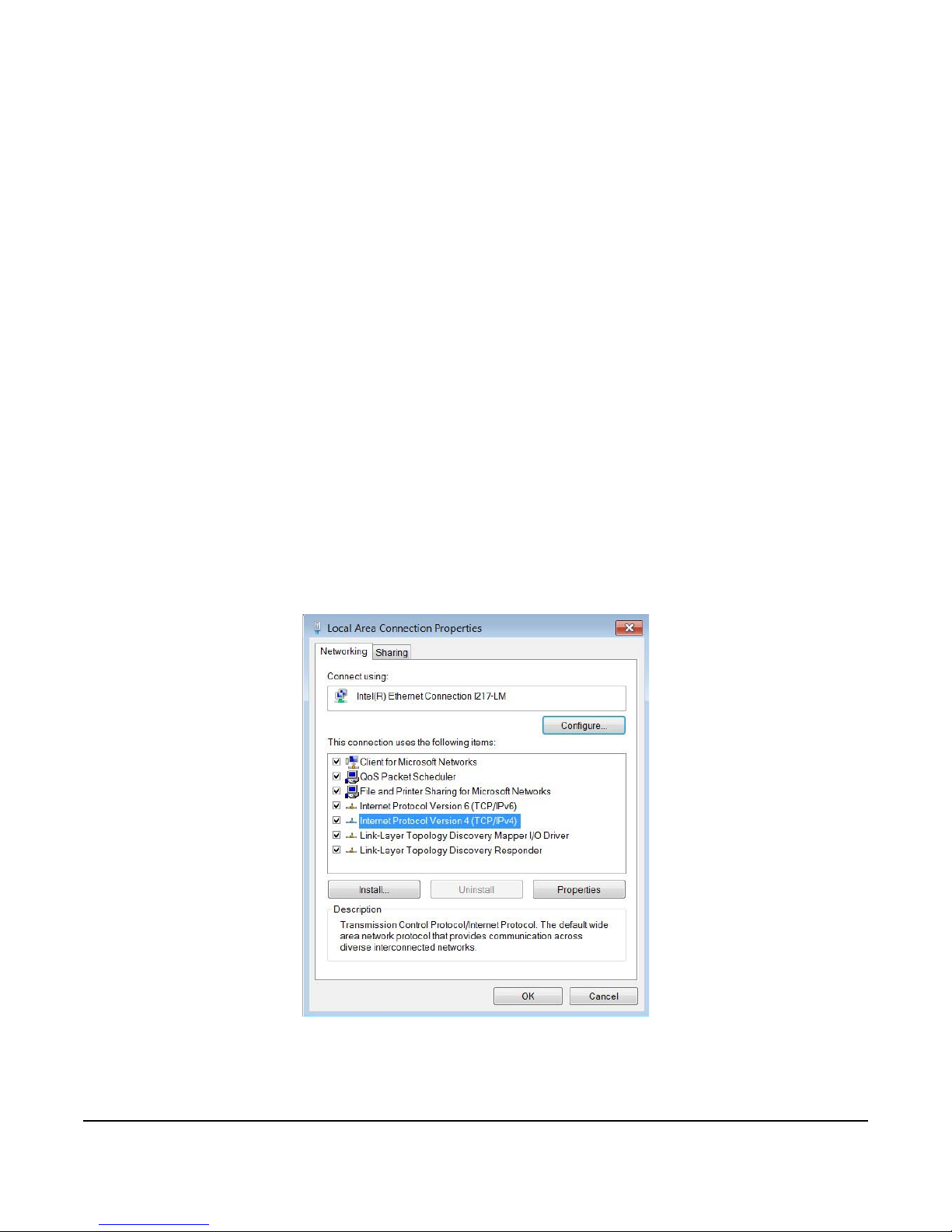
Figure 1: Local Area Connection Properties Dialogue Box
Parts Included
• WT-BAC-IP Gateway
• 12 VDC power adapter
• WT-BAC-IP Installation CD
• WT-BAC-IP Configuration Tool Installation Files
• Product literature
Requirements
• Computer with Windows® 7 or newer
• WT-BAC-IP with firmware revision 1.3.5 or newer
Installing the WT-BAC-IP Gateway Software
From the WT-BAC-IP Installation CD, double-click setup.exe, located under the main WT-BAC-IP Configuration
Tool folder. Follow the on-screen instructions to install the program on the computer.
Establishing an IP Connection to the WT-BAC-IP
Use the following steps to establish an IP connection to the WT-BAC-IP.
1. Configure a temporary static IP address on your computer (Windows 7) by going to Start > Control Panel >
View Network Status and Tasks > Change Adapter Settings.
2. Right-click the Local Area Connection (LAN) icon and select Properties. The Local Area Connection
Properties dialogue box appears.
3. Right-click the Internet Protocol Version 4 (TCP/IPv4) item and click Properties.
4. In the Local Area Connection Properties dialogue box, click the Use the following IP address radio button.
Enter 192.168.35.1 for t he IP address. Ente r 255.255.255.0 for the subnet mask. Se e the following figure. Click
OK.
WT-BAC-IP Gateway Installation Instructions
2
Page 3
Note: Return to the Internet Protocol Version 4 (TCP/IPv4) Properties dialogue box after the WT-BAC-IP is
Figure 2: Internet Protocol Version 4 (TCP/IPv4) Properties Dialogue Box
Figure 3: Back Side of the WT-BAC-IP
installed. Click Obtain an IP address automatically. This option returns your computer back to standard Dynamic
Host Configuration Protocol (DHCP).
5. Connect an Ethernet cable from your computer to the WT-BAC-IP Gateway.
6. Plug the 12 VDC adapter into the WT-BAC-IP.
7. Open the WT-BAC-IP Configuration Tool program.
8. In the By MAC Address tab, type in the MAC address printed on the back of the WT -BAC-IP (in the upper lef thand corner of the product label).
9. Click Connect in the upper right-hand corner of the display window.
WT-BAC-IP Gateway Installation Instructions
3
Page 4
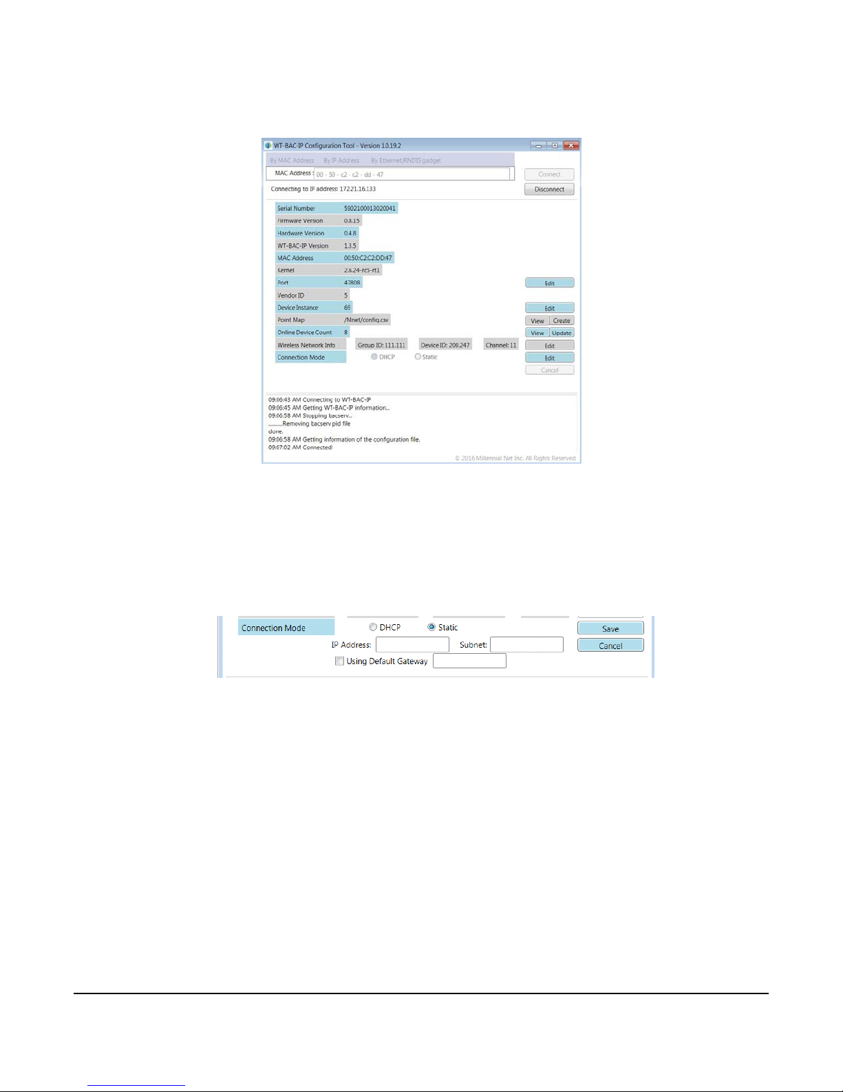
10. Updates appear in the bottom window of the tool. A status update of Connected! appears and the data fields
Figure 4: Connection Established to the WT-B AC-IP
Figure 5: Static IP Display
within the tool are populated as shown in the following figu r e.
Setting IP Connection Parameters
The WT-BAC-IP is configured with a static IP address of 192.168.35.10 out of the box. Use the following steps to
change the static IP address.
1. Click Edit next to the Connection Mode label.
2. Select the Static radio button. Additional parameters for modification appear as shown in the following figure.
3. Enter the intended value for the IP address, the subnet mask, and the applicable va lue if your application
requires the use of a default gateway.
4. Click Save.
5. If the intended application calls for a DHCP connection, simply select the DHCP option and click Save.
Changing the Wireless Network Information
All WT Series devices must share the same Group ID (GID) number in order for them to have a wireless
connection. Each device must have a unique Device ID (DID). All devices must be on the same Communications
Channel. If the GID, DID, or Communication Channel on the WT-BAC-IP need to be modified, this action can be
performed through the WT-BAC-IP Configuration Tool.
Notes:
• If multiple WT-BAC-IPs are installed at the site, you must give each WT -BAC-IP a unique GID. DIDs should not
be repeated across networks.
• The DID high byte should always be in the range of 160 to 255. The DID low byte should always be 247.
WT-BAC-IP Gateway Installation Instructions
4
Page 5
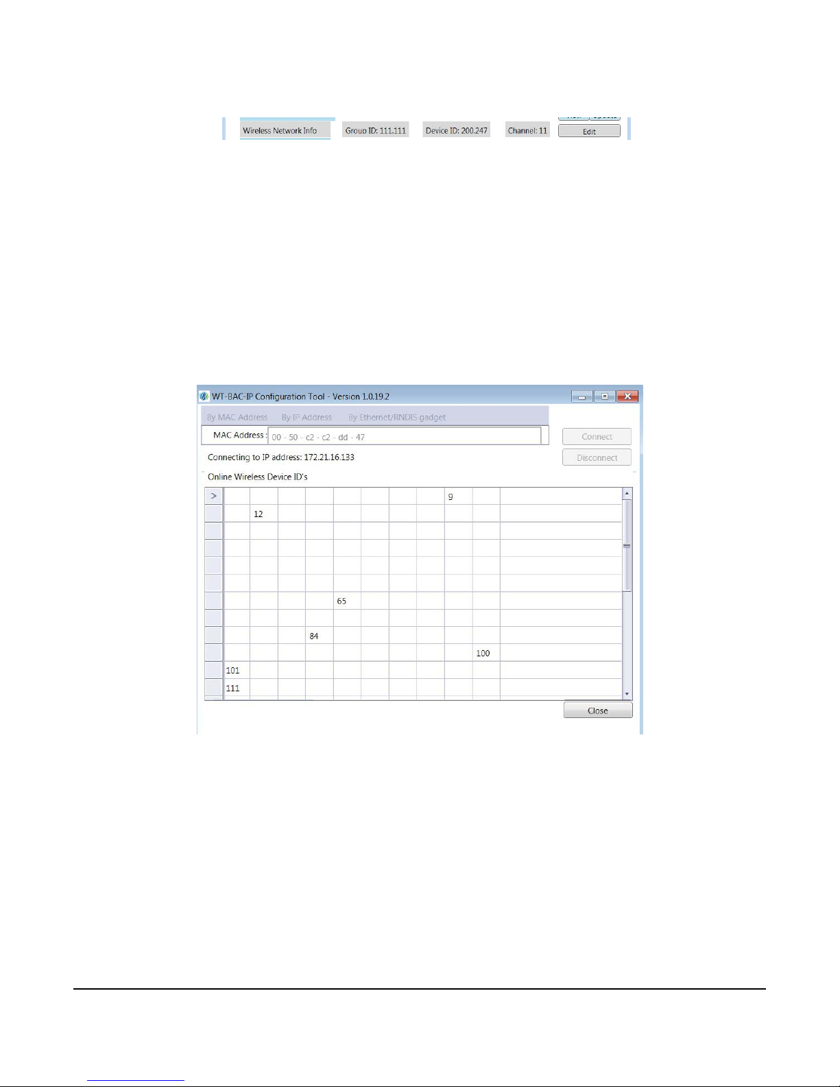
1. In the Wireless Network Info row of the WT-BAC-IP Configuration Tool, click Edit.
Figure 6: Wireless Network Info
Figure 7: Connected Devices Grid
2. Modify the parameters as needed. The DID typically remains at the default 200.247 address.
3. Channels 15, 20, and 25 are recommended as they are between the Wi-Fi communication channels and are
the least susceptible to interference. Check for the best channel before choosing one for the system.
Mapping Connected Devices
Ensure that all WT-4000 Se ries Thermost at s and WT Routers are inst alled an d powered. The GID of devices to be
mapped into the WT-BAC-IP must match.
1. Click View. A grid appears that shows the currently connected devices by their DID. All DIDs in the grid are
currently connected to the gateway.
Note: WT-4000 Series thermostats take up to 5 minutes to appear in the grid.
2. Ensure that the DIDs of all the physically installed devices are present in the grid before proceeding to the next
step.
3. When all devices are connected, you can map their respective BACnet objects by clicking Create.
Note: The Create function creates only BACnet objects for devices that are currently connected. It does not
automatically update the point list when more devices are added. Pe rform the Create function and th e mapping into
the building automation system (BAS) again if more devices are added at a later time.
4. After clicking Create, the dialogue box at the bottom of the tool confirms that the point map has been created.
You can review the point map by clicking View.
WT-BAC-IP Gateway Installation Instructions
5
Page 6
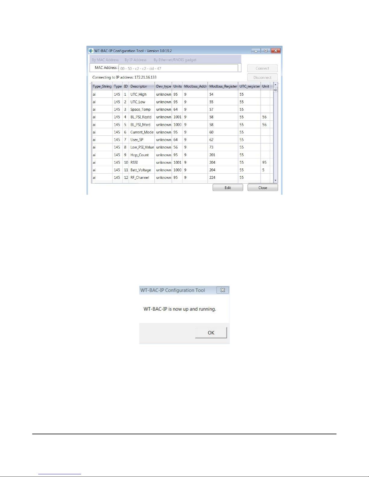
Restarting the BACnet Application
Figure 8: Point Map Representation
Figure 9: WT-BAC-IP Running Notification
The BACnet application that sources dat a for the BACne t objects does not run while the WT-BAC-IP Configuration
Tool configures the WT-BAC-IP. The WT-BAC-IP is not discoverable while the tool is in use.
Perform the following steps to restart the BACnet application and enable discovery of the device.
1. Ensure that all configuration tasks are complete (including changing wireless network addresses, modifying IP
connection parameters, and creating the point map).
2. Click Disconnect in the upper right-han d corner of the tool. Rest arting the WT-BAC-IP takes up to 30 seconds.
The following image appears.
3. The WT-BAC-IP is now running and discoverable from the BAS.
WT-BAC-IP Gateway Installation Instructions
6
Page 7

WT-BAC-IP Gateway Point Mapping
The following table lists the BACnet objects associated with the WT-BAC-IP Gateway. The WT-BAC-IP also
sources BACnet objects for all its connected devices. Refer to the respective documentation for more information
about the BACnet objects.
Table 1: BACnet Objects of the WT-BAC-IP Gateway (Part 1 of 2)
Register
Number
5 Occupancy_Mode Occupancy mode requested by the BAS:
7 Comfort_Up_D Comfort zone upper range relative to system master setpoint; default 3°F;
8 Comfort_Lo_D Comfort zone lower range relative to system master setpoint; default 3°F;
10 Setback_Up_L Upper temperature limit in unoccupied setback mode; default 85°F; maximum
11 Setback_Lo_L Lower temperature limit in unoccupied setback mode; default 55°F; minimum
12 Protect_Up_L Maximum temperature allowed in the zone; default 90°F AV
13 Protect_Lo_L Minimum temperature allowed in the zone; default 50° F AV
14 Override_Period Override duration with one-minute increments; default 120 minutes; maximum
15 Override_Up_D Comfort zone upper delta during override mode; default 5° F; maximum 14° F AV
16 Override_Lo_D Comfort zone lower delta during override mode; default 5° F; maximum 14° F AV
18 Dead_Band Temperature control deadband; default 1° F; maximum 14° F AV
31 Shoulder_Up_D Upper delta; default 5°F.
33 Display_Mode Display mode setting:
54 UTC_High High indicates 16 bits of 32 bit time stamp in UTC format (UNIX epoch time). AI
55 UTC_Low Low indicates 16 bits of 32 bit time stamp in UTC format (UNIX epoch time). AI
57 Space_Temp Space temperature value in °F AI
58 BL_PSI_Rqstd The branch line pressure requested by the unit based on temperature
Point Name Description BACnet
Object
Type
AV
1 – occupied; 2 – constrained float (unoccupied); 3 to 6 – reserved; 7 –
shoulder mode (shallow setback, also used in demand response events)
maximum comfort zone 14° F
maximum comfort zone 14° F
value restricted by Protect_Up_L temperature (register 12)
value restricted by Protect_Lo_L temperature (register 13)
240 minutes
In shoulder mode, the device does not call for cool if space temperature is
below setpoint plus upper delta.
Shoulder_Lo_D Lower delta; default 5°F.
In shoulder mode, device does not call for heat if space temperature is above
setpoint minus lower delta.
0 – normal LCD and button functionality; 1 – temperature is not displayed and
buttons are disabled; 2 – normal LCD functionality but buttons are disabled
If set to any other value, everything is displayed as normal and buttons are
enabled; this feature is not supported in stand-alone mode.
measurement, in PSI.
BL_PSI_Msrd The actual branch line pressure measured by the pressure sensor, in PSI. AI
AV
AV
AV
AV
AV
AV
AV
AV
AI
WT-BAC-IP Gateway Installation Instructions
7
Page 8

Table 1: BACnet Objects of the WT-BAC-IP Gateway (Part 2 of 2)
Register
Point Name Description BACnet
Number
59 MS_Shoulder Bit 10 – motion detector shoulder mode triggered by lack of motion BI
Shoulder_On Bit 7 – shoulder mode button pressed BI
Override_On Bit 6 – override mode button pressed BI
Fan_On Bit 2 – fan on (if applicable) BI
Cool_On Bit 1 – cool on (branch line pressure in cooling zone) BI
Heat_On Bit 0 – heat on (branch line pressure in heating zone) BI
60 Current_Mode The unit’s current mode:
1 – occupied; 2 – constrained float (unoccupied); 3 to 6 – reserved; 7 –
shoulder mode
61 Master_SP The master (system) setpoint specified by the energy management application;
62 User_SP The user setpoint specified by pressing up/down buttons on the unit; default
69 SP_PSI The target branch line pressure when the temperature is at setpoint value;
70 Action_Direction Acting direction: 0 (default) – direct acting; 1 – reverse acting AV
Gain Gain (change in branch line pressure in response to temperature change);
71 Throttle_Range Temperature range when pressure changes in response to temperature
72 Unocc_PSI Branch line pressure when unit is in unoccupied mode and within temperature
73 Low_PSI_Value In the case where Error Reporting Register indicates insufficient pressure,
79 Temp_Unit The unit of temperature; 0 represents °F, and 1 represents °C. The default is
MS_Grace The grace period (number of minutes) that the unit waits for motion detection
201 Hop_Count The number of hops through which the device’s data is routed to reach the
202 1st_Hop_ID_H High byte of device ID of the first hop node AI
1st_Hop_ID_L Low byte of device ID of the first hop node AI
204 RSSI Radio received signal strength (RSSI); signed 8 bit for Modbus register;
Batt_Voltage Battery voltage level in VDC AI
224 RF_Channel The radio channel number used by the device AV
510 Dev_Type This register holds an integer value that identifies the device type in the
default 70°F.
70°F.
default 9.0 PSI; valid range 1.0 to 22.0 PSI.
default 2.0 PSI for each 1°F change; valid range 1.0 to 5.0 PSI.
change; default 6.0° F; valid range 0.0 to 10.0°F.
constrained float limits, in PSI.
this register holds the maximum branch line pressure of the system at that time,
in PSI.
°F. Any change to this value reboots the device.
before it goes into shoulder mode. The default is 30 minutes, and the range is
10 to 100 minutes.
If the unit detects motion while it is in shoulder mode, it comes out of shoulder
mode within 5 minutes.
Motion detection is disabled if this register is set to less than 10 minutes or if
supply pressure is zero.
MeshGate; value 65535 indicates that the device is offline.
BACnet object shows actual value.
wireless network. This is for use by the MeshGate, not for customer
applications.
Object
Type
AI
AV
AI
AV
AV
AV
AV
AI
AV
AV
AI
AI
AI
WT-BAC-IP Gateway Installation Instructions
8
Page 9
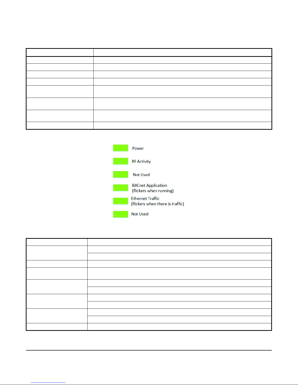
Explanation of Key Attributes
Figure 10: WT-BAC-IP LED Functions
The following table lists the descriptions of key attributes of the WT-BAC-IP Gateway.
Table 2: WT-BAC-IP Key Attributes
Attribute Description
WT-BAC-IP Version Version level for the BACnet application software
MAC Address Unique 12-Digit HEX address for the WT-BAC-IP
Port UDP Port (default value 47808); editable if changes are necessary
Device Instance BACnet Instance ID; can be modified
Point Map View shows currently mapped BACnet objects. Create maps currently connected devices
and creates a new Point Map.
Online Device Count View shows the Grid View of currently connected devices. Update refreshes the co un t to
check for newly connected devices.
Wireless Network Info Shows information about the WT-BAC-IP’s GID, DID, and Channel; all three fields are
Connection Mode Allows the user to switch the WT-BAC-IP between DHCP and Static IP Addressing
editable.
Technical Specifications
WT-BAC-IP Gateway (Part 1 of 2)
Power Requirements 12 VDC external supply
Communications Interface: Ethernet 10Base-T/100Base-TX with RJ-45 Connector
Protocol: BACnet IP
Wireless Band Direct-Sequence, Spread-Spectrum, 2.4 GHz ISM Band
Operating Frequency
Range
Channels Quantity: 15
Transmissions Power: 18 dBm maximum
Ambient Conditions Operating: 50 to 104°F (10 to 40°C), 5 to 95% RH, noncondensing
Materials Gray ABS plastic housing
2,405 to 2,480 MHz
Spacing: 5 MHz
Rate: 250 Kbits for each second
Storage: -4 to 158°F (-20 to 70°C), 5 to 95% RH, noncondensing
WT-BAC-IP Gateway Installation Instructions
9
Page 10

Metasys® and Johnson Controls® are registered trademarks of Johnson Controls.
All other marks herein are the marks of their respective owners. © 2017 Johnson Controls.
Building Technologies & Solutions
507 E. Michigan Street, Milwaukee, WI 53202
WT-BAC-IP Gateway (Part 2 of 2)
Compliance United States:
Transmission Complies with FCC Part 15.247 Regulations for Low Power Unlicensed
Transmitter FCC Identification: HSW-Z2430HPA
RoHS Compliant (EU Directive)
Canada:
Industry Canada IC: 4492A-Z2430HPA
Shipping Weight 0.33 lb (0.15 kg)
European Single Point of Contact: NA/SA Single Point of Contact: APAC Single Point of Contact:
JOHNSON CONTROLS
WESTENDHOF 3
45143 ESSEN
GERMANY
Published in U.S.A. www.johnsoncontrols.com
JOHNSON CONTROLS
507 E MICHIGAN ST
MIL WAUKEE WI 53202
USA
JOHNSON CONTROLS
C/O CONTROLS PRODUCT MANAGEMENT
NO. 22 BLOCK D NEW DISTRICT
WUXI JIANGSU PROVINCE 214142
CHINA
WT-BAC-IP Gateway Installation Ins truct ions
10
 Loading...