

Johnson Controls WT-4002-MCR, WT-4002-MCM, WT-4002-MFR, WT-4002-MFM Installation Instructions Manual
Page 1

WT-4000 Series Pneumatic-to-Direct Digital Control (DDC)
24- 10732- 5, Rev. D
Room Thermostats
Installation Instructions
WT-4002-MCR, WT-4002-MCM,
WT-4002-MFR, WT-4002-MFM
Refer to the QuickLIT website for the most up-to-date version of this document.
Application
The WT-4000 Series Pneumatic-to-Direct Digital
Control (DDC) Room Thermostats provide reliable
zone comfort and enhanced energy economy via
remote monitoring and temperature setpoint
management. This arrangement provides greater
energy policy compliance, and facilitates trending of
floor space usage in commercial, industrial, and
municipal HVAC environments.
The WT-4000 Series Room Thermostats are ideally
suited for energy-saving, pneumatic-to-DDC building
upgrades. Designed for non-invasive replacement
of existing manual pneumatic thermostats, the
WT-4000 Series Room Thermostats provide a number
of DDC features, including remote wireless setpoint
control and occupancy scheduling, and continuous
room temperature, branch line pressure, and battery
status monitoring. All of these features were previously
unavailable in existing pneumatic HVAC control
systems.
The innovative design of the WT-4000 Series Room
Thermostats completely reshapes the pneumatic
HV AC control industry. The room thermostat itself does
not utilize any mechanical parts. A solid state
temperature sensor replaces the bi-metallic strip
elements for precise room temperature mo n ito rin g. In
addition, an advanced piezoelectric air valve replaces
the mechanical relay for improved branch line pressure
control. All of these technologies provide longer, more
dependable, and maintenance-free operation.
Models are available for wireless mesh
communications, or they can be configured in the field
for stand-alone applications. In a wireless mesh
network application, the WT- 4000 Series Room
Thermostat communicates with the controller by
means of a Johnson Controls® WT-ROUTER Router
and Johnson Controls WT-BAC-IP Gateway.
Some WT-4000 Series Room Thermostats include a
binary dry contact input for an occupancy sensor (field
furnished), to detect motion and determine if a space is
occupied. This feature maximizes up to 30% energy
savings in high-energy usage environments such as
schools, dormitories, offices, and hospit als by adjusting
the temperature of the space based on the occupancy
status.
Part No. 24-10732-5, Rev. D
Issued August 2017
All WT-4000 Series Room Thermostats include an
LCD, with either a Fahrenheit or Celsius temperature
display. Depending on the model chosen, the room
thermostat can transmit sensed temperature, setpoint
temperature, occupancy status, and low battery
conditions to an associated router and gateway. The
WT-4000 Series Room Thermostat is designed for
indoor, intra-building applications only.
The WT-4000 Series uses a proprietary
direct-sequence, spread-spectrum RF technology,
and operates on the 2.4 GHz Industrial, Scientific, and
Medical (ISM) band. The room thermostat meets the
IEEE 802.15.4 standard for low power, low duty cycle
RF transmitting systems.
IMPORTANT: The WT -4000 Series
Pneumatic-to-DDC Room Thermostat is intended to
provide an input to equipment under normal
operating conditions. Where failure or malfunction of
the room thermostat could lead to personal injury or
property damage to the controlled equipment or
other property, additional precautions must be
designed into the control system. Incorporate and
maintain other devices, such as supervisory or
alarm systems or safety or limit controls, intended to
warn of or protect against failure or malfunction of
the room thermostat.
IMPORTANT: Le WT-4000 Series
Pneumatic-to-DDC Room Thermostat est destiné à
transmettre des données entrantes à un équipement
dans des conditions normales de fonctionnement.
Lorsqu'une défaillance ou un dysfonctionnement du
room thermostat risque de provoquer des blessures
ou d'endommager l'équipement contrôlé ou un autre
équipement, la conception du système de contrôle
doit intégrer des dispositifs de protection
supplémentaires. Veiller dans ce cas à intégrer de
façon permanente d'autres dispositifs, tels que des
systèmes de supervision ou d'alarme, ou des
dispositifs de sécurité ou de limitation, ayant une
fonction d'avertissement ou de protection en cas de
défaillance ou de dysfonctionnement du room
thermostat.
WT-4 000 Series Pneumatic-to-Direct Digital Control (DDC)
Room Thermostats Installation Instructions
1
Page 2

IMPORTANT: The WT-4000 Series
Pneumatic-to-DDC Room Thermostat is not
designed or intended for use in mission-critical or
life/safety applications.
North American Emissions Compliance
United States
Compliance Statement (Part 15.19)
This device complies with Part 15 of the FCC Rules.
Operation is subject to the following two conditions:
1. This device may not cause harmful interference,
and
2. This device must accept any interference
received, including interference that may cause
undesired operation.
Warning (Part 15.21)
Changes or modifications not expressly approved by
the party responsible for compliance could void the
user’s authority to operate the equipment.
Canada
Industry Canada Statement
The term IC before the certification/registration
number only signifies that the Industry Canada
technical specifications were met.
Installation
The first step of the installation process is to plan the
layout of the devices on the building floor plan. This
process includes identifying the desired locations for all
WT-4000 Series Pneumatic-to-DDC Room
Thermostats, as well as the Johnson Controls
WT-BAC-IP Gateway.
Next, measure the radial distances between each
WT-4000 Ser ies Room Thermostat and the
WT-BAC-IP Gateway, to determine if the distances are
within 200 ft (61 m). If the distance exceeds 200 ft
(61 m), Johnson Controls WT-ROUTER Routers must
be installed to relay signals between each room
thermostat and the associated gateway.
The ideal installation provides each room thermostat
with at least two routes of transmission to the gateway,
to ensure signal transmission success. The nominal
transmission range of each router in a standard
building is 200 ft (61 m). To ensure proper signal
transmission in a wireless mesh network, there should
be at least two routers, or one router and one ga teway,
located within a 200 ft (61 m) radius of every room
thermostat.
In order for the devices to connect to the same mesh
network, they all must have the same group ID. Both
the group ID and the device ID can be changed in the
field; see Net Config Screen
details.
on page 10 for more
Le terme « IC » précédant le numéro d'accréd itation /
inscription signifie simplement que le produit est
conforme aux spécifications techniques d'Industry
Canada.
WT-4000 Series Pneumatic-to-Direct Digital Control (DDC) Room Thermostats Installation Instructions
2
Page 3
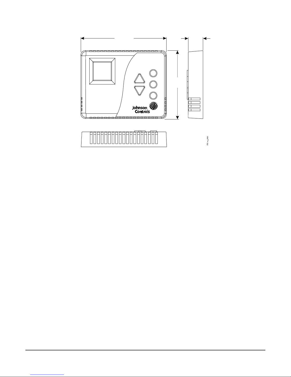
Dimensions
(21)
(95)
(120)
Figure 1: WT-4000 Series Pneumatic-to-DDC Room Thermostat,
Dimensions, in. (mm)
4-23/32
13/16
3-3/4
Mounting
The WT-4000 Series Room Thermostats require the
WT-BAC-IP Gateway and WT-ROUTER Router to
operate as a complete wireless solution. Refer to the
WT-BAC-IP Gateway Installation Instructions
(Part No. 24-10732-21) for details on installing the
gateway, and the WT-ROUTER Router Installation
Instructions (Part No. 24-10732-13) for details on
installing the router.
Tools and Hardware Required
• Couplings or reducers to connect room
thermostats to existing air lines
• Needle nose pliers
• Small level
• Fasteners and anchors to se cure room thermost ats
(site specific)
• Plastic tie wraps to secure routers (site specific)
• Electric drill (optional)
• Building floor plans identifying where the system is
to be installed, serving multiple purposes:
- To plan the wireless network before
installation, by identifying room thermostat
locations
- To document the location of where each
wireless device is installed
Mounting Procedure
Mount the WT- 4000 Series Room Thermostat
according to the steps that follow. Only those
individuals that are experienced with HVAC
maintenance and commercial room thermostats sh ould
perform this installation.
1. Remove the old room thermostat from the
mounting surface and disconnect the air lines
connected to it. Be sure to label the branch line and
the main line.
2. Bend the four locking tabs on the wallplate
outward to separate the wallplate from the new
WT-4000 Series Room Thermostat.
3. Mount the wallplate to the mounting surface:
a. Thread the existing air lines from the wall
through the large opening in the wallplate.
b. Position the wallplate against the mounting
surface to be sure it seats flush with the
surface.
c. Use a small level or visually check that the
wallplate is level.
WT-4000 Series Pneumatic-to-Direct Digital Control (DDC) Room Thermostats Installation Instructions
3
Page 4
d. Mounting holes on the wallplate are designed
Figure 2: LCD during Initialization
to fit a standard electrical box. If additional
mounting holes are required, mark the
locations on the mounting surface.
e. Remove the wallplate from the mounting
surface and drill any additional mounting holes
as needed at each of the marked locations.
f. Use the appropriate mounting hardware (field
furnished) for the specific mounting surface
and secure the wallplate to the surface.
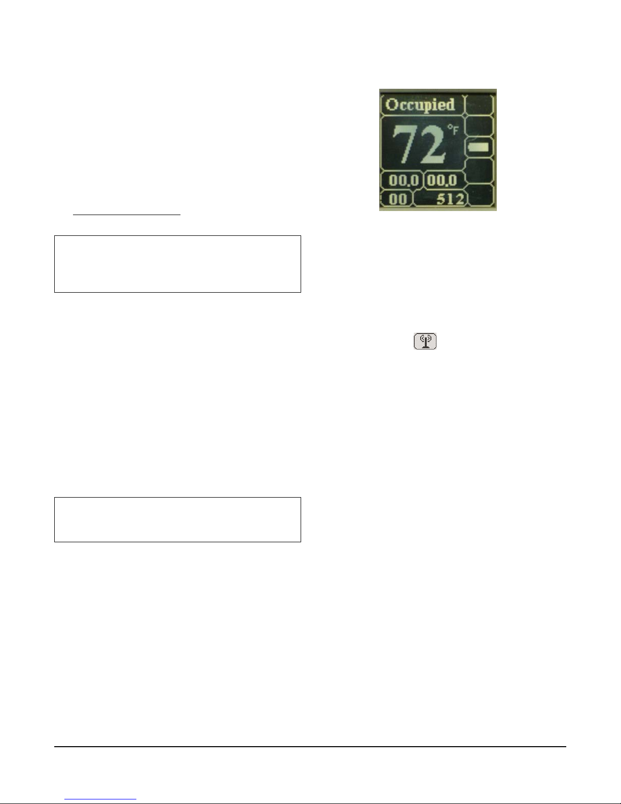
Figure 2 illustrates the LCD during room
thermostat initialization.
4. Connect the air lines to the room thermostat. See
Clean Air Requirements
on page 5 to ensure that
the air supply is clean, dry, and oil-free.
IMPORTANT: Avoid applying excessive pressure
while making the air line connections to the barbed
fittings on the room thermostat. Failure to do so may
damage the room thermostat and void the warranty.
5. Install the four 3.6 V lithium batteries included with
the room thermostat into the battery compartment.
Be sure to match the positive (+) battery ends with
the positive (+) battery terminals in the battery
compartment.
Note: The room thermostat can operate with just two
batteries installed; however, it operates for a
significantly shorter period of time. To maximize battery
life, we recommend that all four batteries be installed.
6. Once powered up, the room thermostat initializes
in:
a. 30 seconds if the room thermostat can connect
to a network.
b. 3 minutes if a network is not present.
IMPORTANT: Do not press any buttons during the
initialization process. Configuration changes made
during initialization are not saved.
FIG:lcd_initliztn
7. Check the wireless connectivity at the intended
room thermostat installation location. It may take
approximately 30 seconds for the room thermostat
to initialize.
a. Look at the wireless connection status
indicator on the room thermostat LCD
(Figure 4). If shows on the upper-right
corner of the LCD, the wireless connection is
established and the room thermostat is
operating properly. If the LCD is blank in the
upper-right corner, there is no wireless
connection.
b. Look at the number of routes to the
WT-BAC-IP Gateway on the room thermostat
LCD (Figure 4). If the number of routes is
blank, the room thermostat is not connected to
the gateway. If the number 1 shows, there is
one connection. If the number 2 shows, there
are two or more connections and the room
thermostat is operating properly.
8. Attach the room thermostat to the previously
installed wallplate by aligning the slot in the room
thermostat housing with the top of the wallplate
and sliding the bottom of the room thermostat
housing over the bottom of the wallplate.
WT-4000 Series Pneumatic-to-Direct Digital Control (DDC) Room Thermostats Installation Instructions
9. Document the device ID and the location of each
room thermostat on the floor plan.
4
Page 5

Safety Measures for Electrostatic Sensitive
Devices (ESDs)
The WT-4000 Series Room Thermostat includes an
ESD-sensitive circuit board. Use caution when
handling the room thermostat when the backplate
(wallplate) is removed. Do not physically touch any part
of the circuit board while connecting air lines, without
wearing ESD protective gear . Even minimal
electrostatic discharge can severely damage the room
thermostat.
Clean Air Requirements
Before installing WT-4000 Series Room Thermostats,
check that the air in the pneumatic lines is properly
cleaned. Clean, dry, and oil-free air in the main supply
line is required for normal room thermostat operation.
The pneumatic system must include a properly
operating air dryer and coalescing air filter that
removes water, oil, and other impurities from the main
supply air before it reaches the room thermostat. If the
existing pneumatic system is contaminated with water
or oil, Johnson Controls recommends installation of a
pre-filter before each room thermostat to protect the
device from contaminants and failure.
Note: Room thermostat failures due to main supply air
contamination with impurities including water, oil, dust,
or other solid particles are not replaceable under the
product warranty.
Johnson Controls recommends using the following
in-line air filter with WT-4000 Series Room
Thermostats:
• Johnson Controls A-4000-1037 In-Line Air Filter
Before installing room thermostats, check for the
following:
• An air dryer that is operating properly
• A coalescing air filter that is replaced and
maintained properly
• In-line air filters before each room thermostat
where necessary
Order of Installation for Wireless Room
Thermostat Models
The WT-4000 Series Room Thermostats look for a
wireless network as soon as they are powered up. We
recommend that the WT-BAC-IP Gateway and
WT-ROUTER Router are installed first to establish a
network connection before the room thermostats are
installed and powered.
If the room thermostats are installed before
establishing a wireless network, be aware of the
following:
• Once powered up, the room thermostat initializes
and looks for a network for 3 minutes. During
initialization, the LCD shows code 512 (Figure 2).
IMPORTANT: Do not press any buttons during the
initialization process. Configuration changes made
during initialization are not saved.
• The room thermostat operates in the Occupied
Mode with the following default settings:
• Setpoint temperature: 70°F (21°C)
• Comfort Zone: ±3F° (±1.8C°)
• The default settings can only be changed from the
controller tool, once the WT-BAC-IP Gateway is
installed.
• Once the WT-BAC-IP Gateway and the
WT-ROUTER Routers are inst alled, check the LCD
on each room thermostat to confirm that they are
connected to the network (Figure 4).
• The default sampling interval is 5 minutes, so it
may take some time for all of the room the rmost at s
to establish a network connection.
In summary, install the components of the mesh
network in the following order:
1. Install the WT-BAC-IP Gateway.
2. Install the WT-ROUTER Routers.
3. Configure the WT -4000 Series Room Th ermostat s;
see Setup and Adjustments
4. Install the WT -4000 Series Room Thermost ats; see
Mounting Procedure
on page 3.
on page 6.
WT-4000 Series Pneumatic-to-Direct Digital Control (DDC) Room Thermostats Installation Instructions
5
Page 6

Setup and Adjustments
Shoulder Mode Button –
Triggers Manual Shoulder
(Unoccupied) Mode
Override Mode Button –
Triggers Manual Override
(Occupied) Mode
Light Button – Lights the
Display for 10 Seconds
Up Button –
Increases the Room
Temperature Setpoint
Down Button –
Decreases the Room
Temperature Setpoint
LCD – See Figure 4
for LCD Details
Figure 3: WT-4000 Series Pneumatic-to-DDC Room Thermostat
Button Descriptions
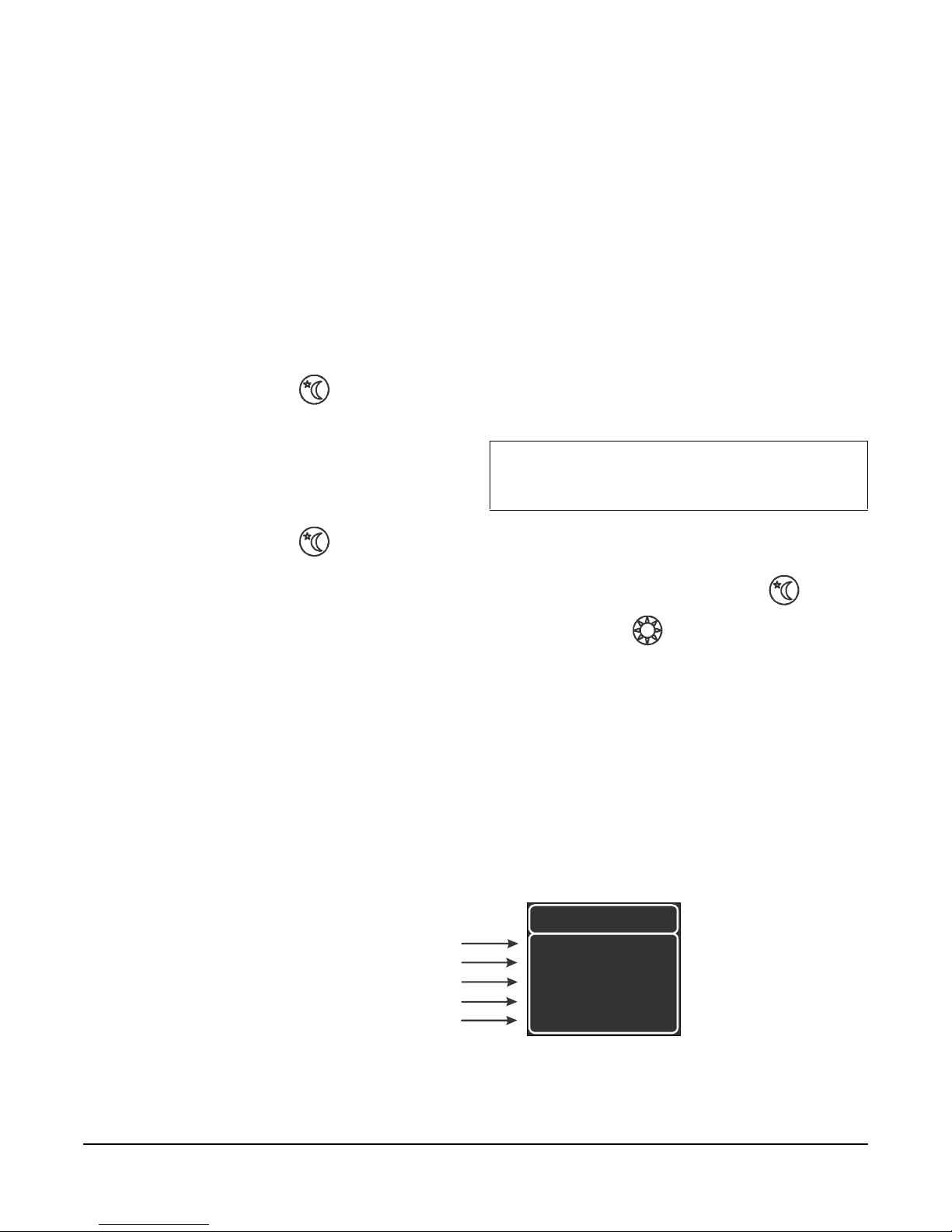
Figure 4: Expanded View of LCD Showing Details
Error Code Display
Fan Outp ut
WT-BAC-IP Ga teway
Requested Branch
Line Pressure (psig)
Received Signal
Strength Indicator
Actual Branch
Line Pressure (psig)
Room Temperature or
Requested Setpoint
(When Up or Down
Buttons ar e Pressed)
Since the room thermostats are battery-po wered
devices with internal memory, they can be configured
prior to, or right after, installation. Johnson Controls
recommends that all of the room thermostats be
configured before installation, to prevent any possible
issues with operation.
Operating Mode
Wireless Connection Status
Number of Routes to the
Battery Voltage Level
Heat or Coo l O utput
FIG:lcd_dtls
WT-4000 Series Pneumatic-to-Direct Digital Control (DDC) Room Thermostats Installation Instructions
6
Page 7
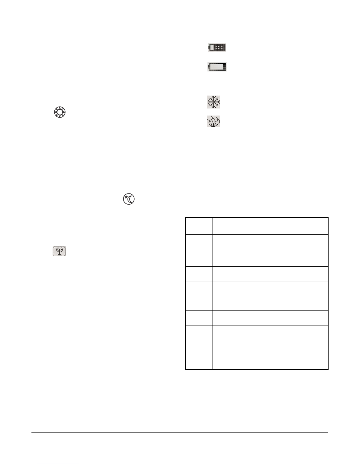
LCD Details
Battery Voltage Level
Operating Mode
a. Occupied – Scheduled Occupied Mode: The
temperature can be adjusted within the
Comfort Zone.
b. Unoccupied – Scheduled Unoccupied
Mode: The HVAC controls are off and the
temperature cannot be adjusted. To turn the
HVAC controls on, press the Override button
to put the room thermostat in the
Override mode, and then adjust the
temperature setting using the Up/Down
buttons.
c. Override – Manual Override Mode: The
temperature can be adjusted within the
Comfort Zone.
d. Shoulder – Manual Unoccupied Mode: The
temperature cannot be adjusted. To put the
room thermostat back to its scheduled mode,
press the Shoulder button again;
Occupied reappears on the main screen.
Wireless Connection Status
Indicates if the room thermostat is connected to the
WT-BAC-IP Gateway.
a. : A connection is established.
b. Blank: There is no connection.
Number of Routes to the WT-BAC-IP Gateway
Indicates how many communication paths exist
between the room thermostat and the WT-BAC-IP
Gateway.
a. Blank: The room thermostat is not connected
to the WT-BAC-IP Gateway.
b. 1: One connection exists.
c. 2: Two or more connections exist and the room
thermostat is operating properly.
a. : The battery is fully charged.
b. : The battery charge is low and the
batteries should be replaced.
Heat or Cool Output
a. : Cooling is on.
b. : Heating is on.
Requested Branch Line Pressure – psig (kPa)
Indicates the required branch line pressure based on
the control calculation.
Actual Branch Line Pressure – psig (kPa)
Indicates the measured values of the branch line
pressure. The actual branch line pressure should be
within 0.6 psig (4 kPa) of the requested branch line
pressure.
Display Codes
Table 1: Display Codes
Display
Description
Code
2 0 psig (0 kPa) available in main line
4 Insufficient branch line pressure
8 Pressure down leak in the system (pressure
12 Insufficient branch line pressure and pressure
16 Pressure up leak in the system (pressure
22 Insufficient branch line pressure and pressure
24 Both pressure down leak and pressure up leak
512 Configuring wireless network
1024 Time and Date need to be configured
Any
Other
Number
decreases when it should remain constant)
down leak in the system
increases when it should remain constant)
up leak in the system
in the system
(Stand-Alone Mode)
Product error; contact the local
Johnson Controls representative
WT-4000 Series Pneumatic-to-Direct Digital Control (DDC) Room Thermostats Installation Instructions
7
Page 8

Received Signal Strength Indicator
Indicates the relative strength of the wireless signal
between the room thermostat and the device it is
communicating with.
a. -39 and higher: A strong and solid wireless
connection exists; no further analysis is
required.
b. -44 to -40: The wireless signal is getting
through; however, the room thermostat should
be monitored. If the signal strength
deteriorates further, there is a risk of data loss.
Consider adding a WT-ROUTER Router
between the devices to strengthen the signal.
c. -45 and lower, or --- : The room thermostat
has a very weak wireless connection or it is
failing to connect to other devices on the
network, resulting in the loss of a significant
number of data packets. The room thermostat
may be located too far from the other devices
or there may be wireless interference in the
area. To strengthen the wireless signal, add a
WT-ROUTER Router between the problematic
devices on the network to create an additional
connection point.
Room Temperature or Requested Setpoint
Indicates the current room temperature. Pressing the
Up/Down buttons once shows the locally-defined
setpoint temperature.
Adjusting the Room Setpoint Temperature
The WT-4000 Series Room Thermostat operates in
conjunction with the preset building configuration
parameters; therefore, the room setpoint temperature
can only be changed within predefined Comfort Zone
limits.
1. Confirm that the room thermostat is in the
scheduled Occupied Mode; the top of the LCD
must read Occupied.
2. The temperature reading on the LCD displays the
current room temperature. To increase or decrease
the room setpoint temperature, press the Up/Down
buttons to select the desired setpoint.
a. When the Up/Down buttons are pressed once,
the LCD shows the user-defined room setpoint
value and the LCD reads Setpoint.
c. When the setpoint is displayed, keep pressing
the Up/Down buttons to reach the desired
room setpoint temperature.
d. If the Up/Down buttons are pressed and the
setpoint stops increasing or decreasing,
predefined Comfort Zone limits have been
reached. If the setpoint does not change, the
local controls are disabled.
Note: Contact the building administrator if the room
temperature minimum or maximum allowable settings
are not comfortable.
e. The room thermostat decides to heat or cool
based on the current room temperature and
the specified setpoint.
3. When the desired setpoint is specified, the LCD
returns to the main screen within 5 seconds.
4. If the LCD reads Unoccupied, the room
thermostat is scheduled to be in the Unoccupied
Mode. If the area requires heating or cooling while
the room thermostat is in the Unoccupied Mode,
press the Override button to change the
room thermostat to the Override Mode. See Using
the Override Mode Button that follows.
Using the Override Mode Button
If the LCD reads Unoccupied, the room thermostat is
scheduled to be in the Unoccupied Mode and the local
room thermostat controls are disabled. If the area
requires heating or cooling:
1. Press the Override button to change the
room thermostat to the Override Mode.
2. The room thermostat stays in the Override Mode,
as defined by the configuration parameters (default
2 hours). The room setpoint temperature can be
adjusted within predefined Comfort Zone limits for
the duration of the Override Mode period.
3. See Step 2 in the Adjusting the Room Setpoint
Temperature section to change the room setpoint
temperature.
4. Once the Override Mode period expires, the room
thermostat returns to its originally scheduled mo de.
If the heating or cooling period needs to be
Note: When the room temperature and the setpoint
value are the same, the HVAC equipment is off.
b. If neither the Up or Down button is pressed
again, the LCD returns to the main screen
within 5 seconds.
WT-4000 Series Pneumatic-to-Direct Digital Control (DDC) Room Thermostats Installation Instructions
extended, press the Override button again
and follow Step 2 in the Adjusting the Room
Setpoint Temperature section.
8
Page 9
Using the Shoulder Mode Button
Figure 5: WT-4000 Series Room Thermostat Firmware Version Screen
CH:
GI:
Device Net w or k G r oup ID
DI:
Unique Thermostat Device ID
DF:
Display Firmware Number
The Shoulder Mode button allows the WT-4000 Series
Room Thermostat to be placed into a shallow setback
mode. When the room thermostat is activated, it does
not use HV AC equipment as lon g as the temperature is
within the Shoulder Mode configured setpoint limits
(default ±5F° [±3C°]).
For example, with a setpoint of 70°F (21°C) and the
Shoulder Mode activated, the room thermostat does
not turn the HVAC equipment on as long as the room
temperature is between 65 and 75°F (18 and 24°C).
Use the Shoulder Mode to save energy wh en a room or
zone is vacated earlier than when the Unoccupied
Mode is scheduled to begin.
Configuration
The following steps describe pre-installation,
device-level configuration.
Room Thermostat Configuration Mode
1. Bend the four locking tabs on the wallplate outward
to separate the wallplate from the room thermost at.
2. Install the four 3.6 V lithium batteries included with
the room thermostat into the battery compartment.
Be sure to match the positive (+) battery ends with
the positive (+) battery terminals in the battery
compartment.
3. Once powered up, the room thermostat initializes
in:
1. Press the Shoulder button to activate the
Shoulder Mode.
2. The Shoulder Mode period has a limited duration;
the room thermostat goes back to its regularly
scheduled mode at the next scheduled Unoccupied
Mode change.
3. Press the Shoulder button again to return to
the Occupied Mode.
a. 30 seconds if the room thermostat can connect
to a network.
b. 3 minutes if a network is not present.
IMPORTANT: Do not press any buttons during the
initialization process. Configuration changes made
during initialization are not saved.
Figure 2 illustrates the LCD during room
thermostat initialization.
4. Press and hold the Shoulder button and the
Override button simultaneously for
6 seconds to set the room thermostat in the
Configuration Mode. Initially, the LCD changes to
the firmware version screen (Figure 5), and then
after 10 seconds the configuration menu appears
(Figure 6).
5. Use the Up/Down buttons to navigate thr o ug h th e
room thermostat menu. All further configuration
settings must be made while in the Configuration
Mode.
Note: If the configuration screen is left idle for
10 seconds, it returns to the normal operation screen.
RF:
Radio Module Firmware Number
WT-4000 Series Pneumatic-to-Direct Digital Control (DDC) Room Thermostats Installation Instructions
Radio Ch annel Num ber
Firmware
DF 0. 3. 37
RF 1. 16. 14
CH 11
GI 111.111
DI 71.40
FIG:frmwr_vrsn_ scrn
9
Page 10

Net Config Screen
Figure 6: Selecting Net Config
Ne
Fa
St
M
M
Figure 7: Selecting CH, GI, or DI
C
G
D
N
I
Figure 8: Selecting Maintenance
N
F
S
M
SPPsi
9.0
Gain
2.0
PropBnd
6.0
0.0
DirActing
Figure 9: Selecting the Pneumatic Settings
SPPsi
9.0
Gain
2.0
PropBnd
6.0
UnocPsi 0.0
DirActing
Figure 10: Changing the Direction
+
-
1. While in the Configuration Mode, press the
Up/Down buttons to select the Net Config option
(Figure 6).
Maintenance – Pneumatic Settings
1. While in the Configuration Mode, press the
Up/Down buttons to select the Maintenance option
(Figure 8).
esh
t Config
n Mode
andalone
aintenance
2. Press to confirm the selection.
3. Press the Up/Down buttons to select CH to change
the radio channel number, GI to change the de vi ce
network group ID, and DI to change the unique
thermostat device ID (Figure 7).
Note: The high byte of the device ID must be in the
range of 71 to 80. The low byte can be set to any value.
etwork
nformation
H11
I 111.111
I 71.40
FIG:nt_cn fg
FIG:ntwrk_infrmtn_ch11
Mesh
et Config
an Mode
tandalone
aintenance
2. Press to confirm the selection.
3. Press the Up/Down buttons to select the
Dir Acting, SP Psi, Gain, Prop Bnd, or Unoc Psi
option (Figure 9).
FIG:mntnce
UnocPsi
4. Press to edit the selected option, which is
FIG:pnmtc_sttngs
4. Press to confirm the selection. The LCD
returns to the normal operation screen, and the
settings are effective immediately.
WT-4000 Series Pneumatic-to-Direct Digital Control (DDC) Room Thermostats Installation Instructions
highlighted on the menu.
5. Change the direction as desired (Figure 10).
FIG:drct_actng
a. Press the Up button to enable direct
acting (Dir Acting).
b. Press the Down button to enable reverse
acting (Rev Acting).
10
Page 11

6. Press to confirm the selection.
SPPsi
9.0
Gain
2.0
PropBnd
6.0
UnocPsi 0.0
DirActing
Figure 11: Changing the Setpoint Pressure
+
-
SPPsi
9.0
Gain
2.0
PropBnd
6.0
0.0
DirActing
Figure 12: Changing the Gain/Sensitivity
+
-
SPPsi
9.0
Gain
2.0
PropBnd
6.0
UnocPsi 0.0
DirActing
Figure 13: Changing the Proportional Band –
Proportional Range/Throttling Range
+
-
SPPsi
9.0
Gain
2.0
PropBnd
6.0
0.0
DirActing
Figure 14: Changing the Unoccupied Mode
Pressure
+
-
11. Change the proportional ba nd – proportional
range/throttling range as desired (Figure 13).
7. Change the setpoint pressure as desired
(Figure 11).
FIG:drct_a ctng
a. Press the Up button to increase the
branch line pressure at setpoint. The valid
range is 1 to 22 psig (7 to 152 kPa), adjustable
in increments of 0.5 psig (3 kPa). The default
setting is 9 psig (62 kPa).
b. Press the Down button to decrease the
branch line pressure at setpoint.
8. Press to confirm the selection.
9. Change the gain/sensitivity as desired
(Figure 12).
FIG:prprt nl_bnd
a. Press the Up button to increase the
proportional band – proportional range/
throttling range. The valid range is 0 to 10F°
(0 to 6C°), adjustable in increments of 1F°
(0.6C°). The default setting is 6F° (3.6C°).
b. Press the Down button to decrease the
proportional band – proportional range/
throttling range.
12. Press to confirm the selection.
13. Change the unoccupied mode pressure as
desired (Figure 14).
UnocPsi
a. Press the Up button to increase the
gain/sensitivity. The valid range is 1 to 5 psi/F°
(13 to 65 kPa/C°), adjustable in increments of
0.5 psig (3 kPa). The default setting is 2 psi/F°
(26 kPa/C°).
b. Press the Down button to decrease the
gain/sensitivity.
10. Press to confirm the selection.
WT-4000 Series Pneumatic-to-Direct Digital Control (DDC) Room Thermostats Installation Instructions
UnocPsi
FIG:gain
a. Press the Up button to increase the
branch line pressure during Unoccupied Mode
periods. The valid range is 0 to 22 psig (0 to
152 kPa), adjustable in increments of 0.5 psig
(3 kPa). The default setting is 0 psig (0 kPa).
b. Press the Down button to decrease the
branch line pressure during Unoccupied Mode
periods.
11
FIG:unoccpd_mde_p rssr
Page 12

14. Press to confirm the selection.
15. Press to go back to the previous screen
button when done.
Note: If the configuration screen is left idle for
10 seconds, it returns to the normal operation screen.
Table 2: WT-4000 Series Room Thermosta t Configurable Settings
Settings Details Range Increments System
Operational
Net Config CH – to change the radio channel number 11 through 26 1 11
GI – to change the device network group ID Two fields separated
DI – to change the unique thermostat device ID Two fields separated
Pneumatic
Direction Direct acting – branch line pressure increase
turns on cooling; decrease turns on heating
Reverse acting – branch line pressure increase
turns on heating; decrease turns on cooling
Setpoint,
psig (kPa)
Gain/
Sensitivity
Proportional
Band –
Proportional
Range/
Throttling
Range
Unoccupied
Mode,
psig (kPa)
Branch line pressure when the room
temperature and setpoint are equal (heating
and cooling outputs are off)
Branch line pressure change needed to change
the room temperature by 1F° (0.6C°)
Temperature range that represents movement
of the controlled device from fully closed to fully
open; typically 6F° (3.6C°) or 4 psi (28 kPa)
Branch line pressure during the Unoccupied
Mode (heating and cooling outputs are off)
Table 2 includes a list of configurable settings that
define how WT-4000 Series Room Thermostat
pneumatic pressure commands correlate with the
temperature values. Refer to the HVAC equipment
documentation or service personnel for the actual
values that should be configured on the room
thermostat.
Defaults
1111.111
by a period; both fields
are 1 through 255
by a period; first field
is 1 through 159, and
second field is
1 through 246
N/A N/A Direct
1 to 22 psig
(7 to 152 kPa)
1 to 5 psi/F°
(13 to 65 kPa/C°)
0 to 10F°
(0 to 6C°)
0 to 22 psig
(0 to 152 kPa)
1 71.40
acting
0.5 psig
(3 kPa)
0.5 psig
(3 kPa)
1F°
(0.6C°)
0.5 psig
(3 kPa)
9 psig
(62 kPa)
2 psi/F°
(26 kPa/C°)
6F°
(3.6C°)
0 psig
(0 kPa)
Commissioning
WT-4000 Series Pneumatic-to-Direct Digital Control (DDC) Room Thermostats Installation Instructions
12
Page 13

Operation
Figure 15: Branch Line Pressure vs. Room Temperature
Gain/
Sensitivity
Setpoint
Pressure
FIG:brnch_ln_prssr
Half of the
1F° (0.6C°)
1F°
(0.6C°)
Dead Zone
±1F° (±0.6C°)
P
p
P
The WT-4000 Series Pneumatic-to-DDC Room
Thermostats are regulated by a number of operational
modes that can be triggered by inputs such a s changes
in inside and outside environments, data received from
other sensing devices, and scheduled times. Each
mode is designed to optimize energy use under certai n
conditions, and has a set of rules that manages
operation of HVAC equipment and restricts local room
thermostat requests.
The two types of operational modes are scheduled and
manual. Scheduled modes are triggered by occu p ancy
schedules, and provide energy savings by aligning the
operation of HVAC equipment to the actual building
occupancy. Manual modes are initiated by the user at
the room thermostat level, and adjust the operation of
HV AC equipment manually outside of the schedule, but
within set energy policy parameters.
The WT-4000 Series Room Thermostats are designed
to support any 0 to 22 psig (0 to 152 kPa) pneumatic
HV AC control system. Variation in bran ch line pressure
is proportional to the deviation of room temp er a tur e
from the setpoint. The proportional factor is determined
by the gain/sensitivity, which is defined as the change
in branch line pressure in p si (kPa) in response to a 1F°
(0.6C°) change in room temperature.
Figure 15 illustrates the linear relationship between
branch line pressure and room temperature, at a give n
setpoint for a Direct Acting (DA) room thermostat
configuration. For a Reverse Acting (RA) room
thermostat configuration, the graph is inverted
horizontally.
a)
sig (k
ressure,
Branch Li ne
Temperature, °F (°C)
Half of the
Proportional Band
Set-
Point
Proportional Band
WT-4000 Series Pneumatic-to-Direct Digital Control (DDC) Room Thermostats Installation Instructions
13
Page 14

In a DA room thermostat configuration, the branch line
Figure 16: LCD during Wireless Communication
pressure increases in response to an increase in room
temperature. When the room temperature is within the
±1F° (±0.6C°) dead zone around the setpoint, the
branch line pressure is regulated at the setpoin t
pressure, and the pneumatic actuator is at the
minimum heat (cool or neutral) position .
When the room temperature rises above the setpoint
plus the dead zone, the branch line pr essure increases
proportionally to the increase in temperature. The
proportional factor is defined by the gain/sensitivity
value.
When the room temperature decreases below th e
setpoint minus the dead zone, the branch line pressure
decreases proportionally to the decrease in
temperature. The proportional band defines the
temperature range, where the branch line pressure
changes proportionally to the change in temperature.
Note: The setpoint pressure, dead zone,
gain/sensitivity, and proportional band are adjusted
using the menu buttons on the WT-4000 Series Room
Thermostat.
Wireless Operation
The WT-4000 Series Pneumatic-to-DDC Room
Thermostats are designed to monitor and control
pneumatic HVAC systems. The room thermostats are
equipped with a 2.4 GHz IEEE 802.15.4 radio that
communicates via a wireless mesh network. The
wireless mesh network forms itself, and data
communications enable remote monitoring,
adjustment, and trending to provide longer and more
dependable and maintenance-free operation.
Note: For each room thermostat in the wireless mesh
network, only one object can be written at a time, and
the next object cannot be written for at least 5 minutes.
In a wireless mesh network, the room thermostat
operates as a battery-powered end node. Being an end
node, the room thermostat does not operate as a router
to relay data for other devices in the mesh network.
Instead, the room thermostat communicates with the
wireless mesh network as an individual device that
transmits and receives its own data only, to and from
the WT-BAC-IP Gateway or through other
WT-ROUTER Routers.
During wireless operation, an antenna icon appears in
the upper-right corner of the LCD when the room
thermostat communicates with the wireless mesh
network (Figure 16). The number below the antenna
icon represents the number of devices that the roo m
thermostat can communicate with. It is desirable that
the room thermostat have two devices it can
communicate with. With two devices, if one
communication link fails, then the other communication
link can be used without delaying any transmissions.
FIG:lcd_cmmnctn
When the room thermostat is installed in buildings with
common sheetrock walls, the nominal radio
communication range of the room thermostat is
approximately 200 ft (61 m). If the room thermostat is
located more than 200 ft (61 m) from the WT-BAC-IP
Gateway , then WT-ROUTER Routers must be installed
to relay data generated by the roo m thermost at back to
the WT-BAC-IP Gateway.
WT-4000 Series Pneumatic-to-Direct Digital Control (DDC) Room Thermostats Installation Instructions
14
Page 15

Stand-Alone Operation
Figure 17: LCD during Stand-Alone Operation
Stand-Alone Room Thermostat Occupancy
Programming
The WT-4000 Series Room Thermostats can operate
as stand-alone pneumatic-to-DDC room thermostats
with an independent time clock, and can be
programmed with a Weekday/Weekend occupancy
schedule.
During stand-alone operation, a person icon appear s in
the upper-right corner of the LCD (Figure 17). When
the room thermostat is powered up for the first time, the
number 1024 appears on the bottom of the LCD
indicating that the time and date need to be set before
the device can operate according to the occupancy
schedule.
FIG:lcd_oc cpncy
A complete 7-day schedule consists of two
independent components:
• Weekday Schedule – Monday through Friday
• Weekend Schedule – Saturday through Sunday
Each component is split into two parts to be scheduled
as Occupied or Unoccupied Mode:
• Weekday 1
• Weekday 2
• Weekend 1
• Weekend 2
Each part can be configured to Occupied or
Unoccupied Mode independently, to accommodate for
daytime or nighttime shift schedules.
For each Occupied Mode, the following features can be
configured:
• Occupied Mode start time
• Temperature setpoint range – adjustable ±14F°
(±8.4C°) by the room occupants
For each Unoccupied Mode, the following features can
be configured:
• Unoccupied Mode start time
• Upper temperature limit
• Lower temperature limit – the room thermostat is
off while the room temperature is within these limit s
WT-4000 Series Pneumatic-to-Direct Digital Control (DDC) Room Thermostats Installation Instructions
15
Page 16

The start time of each schedule part is automatically
Weekday1
Occupied
07:00
70
Setpoint Temperature
(Defines the Occupied Mode
setpoint temperature of the part.)
Weekday 1, Weekday 2,
Weeke nd 1, or Weekend 2
Occupied or Unoccupied
(Defines the occu pancy
mode of the part. )
Time in 24-Hour Format
Figure 18: WT-4000 Series Pneumatic-to-DDC Room Thermostat
Schedule Setup Screen for Occupied Mode
Weekday 1, Weekday 2,
Weekend 1, or Weekend 2
Occupied or Unoccupied
(Define s th e occupancy
mode of the part. )
Lower Temperature Limit
(Defines the Unoccupied Mode
Weekday2
Unoccupied
18:00
85 55
Time in 24-Hour Format
Figure 19: WT-4000 Series Pneumatic-to-DDC Room Thermostat
Schedule Setup Screen for Unoccupied Mode
the end time of the previous schedule part. For
example, when the occupied schedule is 6 A.M. to
6 P.M., the Occupied Mode starts at 6 A.M. and the
Unoccupied Mode starts at 6 P.M. Figure 18 and
Figure 19 illustrate the Occupied and Unoccupied
Mode schedule setup.
(Defines which part i s being edited .)
(Define s th e st art time of th e part.)
FIG:occpd_mde
(Defines which par t is being edited . )
Upper T emperature Limit
(Defines the Unoccupied Mode
upper te m perature li m i t of t he part.)
(Define s the start time of the part.)
lower temperatur e l imit of the pa r t.)
FIG:unoccpd _mde
WT-4000 Series Pneumatic-to-Direct Digital Control (DDC) Room Thermostats Installation Instructions
16
Page 17

Configuring the Room Thermostat for Stand-Alone
-
+
Figure 20: Selecting Mesh
N
F
S
M
-
+
+
-
Figure 21: Stand-Alone Menu
N
F
S
M
S
Operation
The WT-400 0 Series Room Thermostats can be
configured in the field for stand-alone applications.
Stand-Alone Room Thermostat Configuration
To set the time and program the stand-alone room
thermostat occupancy schedule and temperature
setpoints:
1. Press and hold the Shoulder button and the
Override button simultaneously for at least
6 seconds.
2. Press the Down button to enter the menu,
then press the press the Up button to select
Mesh on the menu (Figure 20).
Mesh
et Config
an Mode
tandalone
aintenance
FIG:mntnce
3. Press to confirm the selection.
1. Press and hold the Shoulder button and the
Override button simultaneously for
10 seconds to set the room thermostat in the
Configuration Mode. Initially, the LCD changes to
the firmware version screen, and then after
10 seconds the configuration menu appears.
Confirm that the first line in the configuration menu
shows Standalone; if it indicates Mesh, switch to
Standalone (Figure 21).
a. Press the Up button .
b. Press to select.
c. Press the Up button or the Down button
to change the value.
d. Press to confirm the selection.
4. Press the Down button to select Standalone
on the menu.
5. Press to confirm the selection.
6. Press to return to the main screen. After the
room thermostat resets, a person icon appears in
the upper-right corner of the LCD indicating
stand-alone operation.
tandalone
et Config
an Mode
tandalone
aintenance
FIG:stndl n
WT-4000 Series Pneumatic-to-Direct Digital Control (DDC) Room Thermostats Installation Instructions
17
Page 18

2. Use the Up/Down buttons to select Standalone on
Figure 22: Selecting the Stand-Alone Mode
N
F
S
M
S
Standalone
Date&Time
Weekday
Weekend
Figure 23: Selecting Date and Time
Figure 24: Setting the Date and Time
+
-
+
-
Weekday1
Occupied
07:00
70
FIG:wdy_1
Figure 25: Setting the Weekday 1 Schedule
+
-
+
-
the menu (Figure 22).
7. Press to confirm the selection.
tandalone
et Config
an Mode
tandalone
aintenance
3. Press to confirm the selection.
4. Select Date & Time on the menu (Figure 23) and
press to enter the setup screen.
FIG:stndln_mde
FIG:dte_tme_mnu
8. Repeat Step5 through Step 7 until all of the menu
options are configured correctly. Press the Up
button or the Down button to scroll
through the date and time menu options.
9. While in the configuration menu, use the Up/Down
buttons to navigate to Weekday to program the
weekday schedule.
10. Press to open the weekday schedule.
11. Set the Weekday 1 schedule (Figure 25), which is
usually the start of the Occupied Mode.
a. Leave the top line as Weekday 1.
5. In the Date & Time menu (Figure 24), press
to highlight the menu options that require editing.
Year2014
Month01
Day01
Hour01
Minute01
6. Press the Up button or the Down button
to change the value.
FIG:dte_t me_sttn gs
b. Press the Up button or the Down button
to scroll through the occupancy mode,
start time, and lower temperature limit menu
items.
c. Press to open a specific menu item.
d. Press the Up button or the Down button
to change the value, then press to
save the setting.
WT-4000 Series Pneumatic-to-Direct Digital Control (DDC) Room Thermostats Installation Instructions
18
Page 19

12. Set the Weekday 2 schedule (Figure 26).
Weekday2
Unoccupied
18:00
85
Figure 26: Setting the Weekday 2 Schedule
+
-+-
+-+
-
Figure 27: Selecting Weekend
Standalone
Date&Time
Weekday
Weekend
f. Press to open a specific menu item.
g. Press the Up button or the Down button
to change the value, then press to
55
FIG:wkdy_2
a. Press the Up button or the Down button
to navigate to Weekday 1.
b. Press to highlight the selection.
c. Press the Up button or the Down button
to change the selection to Weekday 2.
d. Press to save the setting.
e. Press the Up button or the Down button
to scroll through the occupancy mode,
save the setting.
13. While in the configuration menu, use the Up/Down
buttons to navigate to Weekend (Figure 27).
FIG:dte_ wknd_mnu
14. Program the weekend schedule in a similar
manner as the weekday schedule.
15. Once all programming is complete, press to
exit the Configuration Mode.
start time, upper temperature limit, and lower
temperature limit menu items.
WT-4000 Series Pneumatic-to-Direct Digital Control (DDC) Room Thermostats Installation Instructions
19
Page 20

Occupancy Programming Example – Standard
Weekend1
Unoccupied
09:00*
85 55
Weekend 2
Unoccupied
17:00*
85
FIG:stndrd_offc_hrs
Weekday1
Occupied
09:00
70
Weekday2
Unoccupied
17:00
85
55
* The star t and end time s ar e irrelevant, since bo th w eekend par t s ar e set to the sa m e unoccupi ed m ode.
Figure 28: Occupancy Programming Schedule;
Standard Office Hours
FIG:nght_shft_hr s
Weekday1
Unoccupied
06:00
85 55
Weekday2
Occupied
15:00
70
Weekend 1
Unoccupied
85
55
Weekend 2
Occupied
70
Figure 29: Occupancy Programming Schedule;
Night Shift Hours
Office Hours
• Setpoint: 70°F
• Occupied from 9 A.M. to 5 P.M., Monday through
Friday
• Saturday and Sunday: Unoccupied, Upper Limit is
85°F, Lower Limit is 55°F
Program the WT-4000 Series Room Thermostat
schedule setup screens as illustrated in Figure 28.
55
Occupancy Programming Example – Night Shift
Hours
• Setpoint: 70°F
• Occupied from 3 P.M. to 6 A.M., Monday through
Sunday
Program the WT-4000 Series Room Thermostat
schedule setup screen as illustrated in Figure 29.
06:00
15:00
WT-4000 Series Pneumatic-to-Direct Digital Control (DDC) Room Thermostats Installation Instructions
20
Page 21

Occupancy Programming Example – Extended
Weekday1
Occupied
08:00
70
Weekday2
Unoccupied
18:00
85
55
Weekend 1
Occupied
70
Weekend2
Unoccupied
85
Figure 30: Occupancy Programming Schedule;
Extended Office Hours with Weekend Schedule
Office Hours with Weekend Schedule
• Setpoint: 70°F
• Occupied from 8 A.M. to 6 P.M., Monday through
Friday
• Occupied from 10 A.M. to 1 P.M. , Saturday and
Sunday
Program the WT-4000 Series Room Thermostat
schedule setup screen as illustrated in Figure 30.
Room Thermostat Operational Modes
Scheduled Modes
Scheduled WT-4000 Series Pneumatic-to-DDC Room
Thermostat operational modes are regulated by the
HVAC schedules, as defined by the user. The HVAC
schedules can be set in advance through the building
automation system for wireless communicating
models, and locally at each room thermostat for
stand-alone models. The room thermost at executes the
HVAC schedules automatically.
Occupied Mode
Use the Occupied Mode when the room is scheduled to
be occupied. During the Occupied Mode, the room
temperature is defined by two values set by the room
thermostat configuration parameters:
• Setpoint – the targeted room temperature for the
season
• Comfort Zone – the optimal temperature range
around the setpoint
The room thermostat maintains the room temperature
within the Comfort Zone. If the room temperature falls
outside of the range of the Comfort Zone, the room
thermostat reacts accordingly and automatically
requests heating or cooling.
10:00
The room thermostat allows users to adjust the room
temperature using the local room thermostat, as long
as the desired room temperature is within the range of
the Comfort Zone. If the user requests heating or
cooling outside of the range of the Comfort Zone, the
request at the local room thermostat is overwritten by
the room thermostat configuration parameters.
Example: The setpoint temperature is 70°F (21°C) and
the range of the Comfort Zone is ±3F° (±1.8C°) around
the setpoint temperature. The user is manually able to
affect the room temperature only between 67 and 73°F
(19 and 23°C), regardless of the temperature
requested on the LCD of the local room thermostat.
Stand-alone room thermostats do not feature a
configurable Comfort Zone. Instead, stand-alone
models have a factory set range of ±14F° (±8.4C°)
around the installer-configured setpoint tempera ture in
the Occupied Mode.
Unoccupied Mode
Use the Unoccupied Mode to save energy during tho se
times when a room is unoccupied. The room
thermostat does not call for heating or cooling when the
room temperature is within the upper and lower
Unoccupied Mode temperature limits. If the room
temperature falls outside of the upper and lower
Unoccupied Mode temperature limits, the room
thermostat calls for heating or cooling to bring th e room
temperature back within the Unoccupied Mode upper
and lower temperature limits.
13:00
55
FIG:extnd_offc_hrs
WT-4000 Series Pneumatic-to-Direct Digital Control (DDC) Room Thermostats Installation Instructions
21
Page 22

Manual Modes
The following manual modes cannot be scheduled or
triggered remotely. Instead, these manual modes can
only be initiated locally via user interface with the room
thermostat. All parameter-defining rules of each mode
are configurable; see Table 3.
Override Mode
Press the Override button on th e ro om
thermostat to initiate the Override Mode. The Override
Mode has a limited duration time, set by the room
thermostat configuration parameters. After the Override
Mode expires, the room thermostat returns to its
regularly scheduled mode.
The Override Mode overrides the scheduled Occupied
Mode or Unoccupied Mode by allowing the user to
control the HVAC system through the local thermostat,
and it permits a wider Comfort Zone range. If the room
temperature is outside the Override Comfort Zone
range, the room thermostat disables the local
thermostat controls.
The Override Mode Comfort Zone range and the
Override Mode duration time are set by the room
thermostat configuration parameters; see Table 3.
Shoulder Mode
Press the Shoulder button on th e WT-4000
Series Room Thermostat to initiate the energy saving
transition from the Occupied Mode to the Unoccupied
Mode. While in the Shoulder Mode, the room
thermostat does not call for heating or cooling when the
room temperature is between the upper and lower
Shoulder Mode Comfort Zone temperat ur e limits.
Use the Shoulder Mode to manually set back the room
temperature setpoint if occupants leave the facility
earlier than the scheduled time. Doing so essentially
overrides the current schedule, until the next scheduled
mode change occurs. For example, when the zone is
running a 5-day, 8 A.M. to 6 P.M. occupancy schedule
but one day the occupants are leaving at 2 P.M., the
zone can be manually set into Shoulder Mode at 2 P.M.
The room thermostat remains in Shoulder Mod e until
6 P.M., at which time it follows its regular schedule
again.
The upper and lower Shoulder Mode Comfort Zone
temperature limits are set by the room thermostat
configuration parameters; see Table 3.
Note: The Shoulder Mode can also be used as a
Demand Response Mode, which can be triggered
remotely from the monitoring and control application.
Fail-Safe Features
The WT-4000 Series Pneumatic-to-DDC Room
Thermostats have a number of programmed fail-safe
features that ensure continuous HV AC operation. In the
event of a communication failure with the WT-BAC-IP
Gateway, the wireless network, or the HVAC
equipment, a fail-safe mechanism ensures that the
devices continue to operate in logical fashion. Once the
failure condition no longer exists, the devices recover
from fail-safe mode and resume normal operation.
Loss of Radio Communication with Site Controller
If the room thermostat experiences radio
communication failure with the WT-BAC-IP Gateway,
the room thermostat automatically goes into the
Occupied Mode. When the room thermostat regains
communication with the WT-BAC-IP Gateway, the
room thermostat automatically receives updated mode
status, setpoint values, and other configuration
commands based on the latest user schedule.
Protection Zone
To protect building infrastructure, equipment, and
occupants, the room thermostat has extreme
temperature limits (configurable by the user) that allow
temperatures to float independently from any mode
settings. If these temperature limits are reached, the
room thermostat automatically reacts and adjusts
heating or cooling despite what scheduled mode is
running. The protection zone default value for the
upper temperature limit is 95°F (35°C) and the lower
temperature limit is 40°F (4°C).
WT-4000 Series Pneumatic-to-Direct Digital Control (DDC) Room Thermostats Installation Instructions
22
Page 23

WT-4000 Series Pneumatic-to-DDC Room
Thermostat Configuration Parameters
The variables included in Table 3 define the
WT-4000 Series Pneumatic-to-DDC Room Thermostat
configuration parameters and regulate r oom thermostat
operation.
Table 3: WT-4000 Series Room Thermostat Configuration Parameters (Part 1 of 2)
Parameter Description Configuration
Method
Occupied Mode
Setpoint value Zone setpoint temperature Configuration tool
Comfort Zone upper delta;
default = 3F° (1.8C°)
Comfort Zone lower delta;
default = 3F° (1.8C°)
Unoccupied Mode
Constrained float upper limit;
default = 85°F (29°C)
Constrained float lower limit;
default = 55°F (13°C)
Override Mode
Override duration;
default = 120 minutes
Override Mode
Comfort Zone upper delta;
default = 14F° (8.4C°)
Override Mode
Comfort Zone lower delta;
default = 14F° (8.4C°)
Other Parameters
Network configuration
(Net Config)
Operational modes 1: Occupied
Dead zone delta;
default = 1F° (0.6C°)
Room thermostat protection
zone – upper limit;
default = 95°F (35°C)
Room thermostat protection
zone – lower limit;
default = 40°F (4°C)
Default Occupied Mode start
time in the event of wireless
communication failure;
default = 06:00 A.M.
Upper temperature bound on deviation from configuration
parameters setpoint during Occupied Mode
Lower temperature bound on deviation from parameter setpoint
during Occupied Mode
Defines upper temperature limit in Unoccupied Mode;
HVACequipment remains off while the zone temperature is
between the upper and lower limits
Defines lower temperature limit in Unoccupied Mode;
HVACequipment remains off while zone temperature is
between the upper and lower limits
Room thermostat override duration (240 minute maximum
duration); after time limit expires, room thermostat goes into
regularly scheduled mode
Comfort Zone upper delta during Override Mode Configuration tool
Comfort Zone lower delta during override Mode Configuration tool
CH: To change the radio channel number; default = 11
GI: To change the device network group ID; default = 111.111
DI: To change the unique thermostat device ID; default = 71.40
2: Unoccupied
Temperature range around setpoint, to prevent HVAC from
chattering
Maximum temperature allowed in zone; fail-safe feature
applicable to all zones
Minimum temperature allowed in zone; fail-safe feature
applicable to all zones
Time of day (0 to 24 hours) in the event the room thermostat
goes offline for an extended duration
Configuration tool
Configuration tool
Configuration tool
Configuration tool
Configuration tool
Configuration tool,
room thermostat
Factory configured
Configuration tool
Factory configured
Factory configured
Factory configured
WT-4000 Series Pneumatic-to-Direct Digital Control (DDC) Room Thermostats Installation Instructions
23
Page 24

Table 3: WT-4000 Series Room Thermostat Configuration Parameters (Part 2 of 2)
Parameter Description Configuration
Method
Default Occupied Mode setpoint
value in the event of wireless
communication failure;
default = 70°F (21°C)
Default Unoccupied Mode
setpoint start time in the event of
wireless communication failure
Temperature sensor
calibration factor; °F (°C)
Shoulder Mode Comfort Zone
upper delta
Shoulder Mode Comfort Zone
lower delta
Direction Direct acting – branch line pressure increase turns on cooling;
Setpoint psig Branch line pressure when room temperature and setpoint are
Gain/sensitivity Branch line pressure change needed to change the room
Proportional band – proportional
range/throttling range
Unoccupied Mode psig Branch line pressure during Unoccupied Mode when zone
T emperature used in the event the room thermostat goes offline
for an extended duration
Time of day (0 to 24 hours) in the event the room thermostat
goes offline for an extended duration; disabled in default
configuration; therefore, device does not go into Unoccupied
Mode when offline
Calibrates the room thermostat temperature sensor for offset
compensation
Defines upper temperature limit in Shoulder Mode Configuration tool
Defines lower temperature limit in Shoulder Mode C onfiguration tool
decrease turns on heating
Reverse acting – branch line pressure increase turns on
heating; decrease turns on cooling
equal (no heating or cooling outputs)
temperature by 1F° (0.6C°)
Temperature range that represents the controlled device’s
movement from fully closed to fully open; typically 4F° (2.4C°)
or 6F° (3.6C°)
temperature is within unoccupied constrained upper and lower
limits
Factory configured
Factory configured
Factory configured
Configuration tool,
room thermostat
Configuration tool,
room thermostat
Configuration tool,
room thermostat
Configuration tool,
room thermostat
Configuration tool,
room thermostat
WT-4000 Series Pneumatic-to-Direct Digital Control (DDC) Room Thermostats Installation Instructions
24
Page 25

Table 4: BACnet Objects of the WT-BAC-IP Gateway (Part 1 of 2)
Register
Point Name Description BACnet
Number
5 Occupancy_Mode Occupancy mode requested by the BAS:
7 Comfort_Up_D Comfort zone upper range relative to system master setpoint; default 3°F;
8 Comfort_Lo_D Comfort zone lower range relative to system master setpoint; default 3°F;
10 Setback_Up_L Upper temperature limit in unoccupied setback mode; default 85°F; maximum
11 Setback_Lo_L Lower temperature limit in unoccupied setback mode; default 55°F; minimum
12 Protect_Up_L Maximum temperature allowed in the zone; default 90°F AV
13 Protect_Lo_L Minimum temperature allowed in the zone; default 50° F AV
14 Override_Period Override duration with one-minute increments; default 120 minutes; maximum
15 Override_Up_D Comfort zone upper delta during override mode; default 5° F; maximum 14° F AV
16 Override_Lo_D Comfort zone lower delta during override mode; default 5° F; maximum 14° F AV
18 Dead_Band Temperature control deadband; default 1° F; maximum 14° F AV
31 Shoulder_Up_D Upper delta; default 5°F.
Shoulder_Lo_D Lower delta; default 5°F.
33 Display_Mode Display mode setting:
54 UTC_High High indicates 16 bits of 32 bit time stamp in UTC format (UNIX epoch time). AI
55 UTC_Low Low indicates 16 bits of 32 bit time stamp in UTC format (UNIX epoch time). AI
57 Space_Temp Space temperature value in °F AI
58 BL_PSI_Rqstd The branch line pressure requested by the unit based on temperature
BL_PSI_Msrd The actual branch line pressure measured by the pressure sensor, in PSI. AI
59 MS_Shoulder Bit 10 – motion detector shoulder mode triggered by lack of motion BI
Shoulder_On Bit 7 – shoulder mode button pressed BI
Override_On Bit 6 – override mode button pressed BI
Fan_On Bit 2 – fan on (if applicable) BI
Cool_On Bit 1 – cool on (branch line pressure in cooling zone) BI
Heat_On Bit 0 – heat on (branch line pressure in heating zone) BI
60 Current_Mode The unit’s current mode:
61 Master_SP The master (system) setpoint specified by the energy management application;
1 – occupied; 2 – constrained float (unoccupied); 3 to 6 – reserved; 7 –
shoulder mode (shallow setback, also used in demand response events)
maximum comfort zone 14° F
maximum comfort zone 14° F
value restricted by Protect_Up_L temperature (register 12)
value restricted by Protect_Lo_L temperature (register 13)
240 minutes
In shoulder mode, the device does not call for cool if space temperature is
below setpoint plus upper delta.
In shoulder mode, device does not call for heat if space temperature is above
setpoint minus lower delta.
0 – normal LCD and button functionality; 1 – temperature is not displayed and
buttons are disabled; 2 – normal LCD functionality but buttons are disabled
If set to any other value, everything is displayed as normal and buttons are
enabled; this feature is not supported in stand-alone mode.
measurement, in PSI.
1 – occupied; 2 – constrained float (unoccupied); 3 to 6 – reserved; 7 –
shoulder mode
default 70°F.
Object
Type
AV
AV
AV
AV
AV
AV
AV
AV
AV
AI
AI
AV
WT-4000 Series Pneumatic-to-Direct Digital Control (DDC) Room Thermostats Installation Instructions
25
Page 26

Table 4: BACnet Objects of the WT-BAC-IP Gateway (Part 2 of 2)
Register
Point Name Description BACnet
Number
62 User_SP The user setpoint specified by pressing up/down buttons on the unit; default
70°F.
69 SP_PSI The target branch line pressure when the temperature is at setpoint value;
70 Action_Direction Acting direction: 0 (default) – direct acting; 1 – reverse acting AV
Gain Gain (change in branch line pressure in response to temperature change);
71 Throttle_Range Temperature range when pressure changes in response to temperature
72 Unocc_PSI Branch line pressure when unit is in unoccupied mode and within temperature
73 Low_PSI_Value In the case where Error Reporting Register indicates insufficient pressure,
79 Temp_Unit The unit of temperature; 0 represents °F, and 1 represents °C. The default is
MS_Grace The grace period (number of minutes) that the unit waits for motion detection
201 Hop_Count The number of hops through which the device’s data is routed to reach the
202 1st_Hop_ID_H High byte of device ID of the first hop node AI
1st_Hop_ID_L Low byte of device ID of the first hop node AI
204 RSSI Radio received signal strength (RSSI); signed 8 bit for Modbus register;
Batt_Voltage Battery voltage level in VDC AI
224 RF_Channel The radio channel number used by the device AV
510 Dev_Type This register holds an integer value that identifies the device type in the
default 9.0 PSI; valid range 1.0 to 22.0 PSI.
default 2.0 PSI for each 1°F change; valid range 1.0 to 5.0 PSI.
change; default 6.0° F; valid range 0.0 to 10.0°F.
constrained float limits, in PSI.
this register holds the maximum branch line pressure of the system at that time,
in PSI.
°F. Any change to this value reboots the device.
before it goes into shoulder mode. The default is 30 minutes, and the range is
10 to 100 minutes.
If the unit detects motion while it is in shoulder mode, it comes out of shoulder
mode within 5 minutes.
Motion detection is disabled if this register is set to less than 10 minutes or if
supply pressure is zero.
MeshGate; value 65535 indicates that the device is offline.
BACnet object shows actual value.
wireless network. This is for use by the MeshGate, not for customer
applications.
Object
Type
AI
AV
AV
AV
AV
AI
AV
AV
AI
AI
AI
Repair Information
If the WT-4000 Series Pneumatic-to-DDC Room
Thermostat fails to operate within its specifications,
replace the unit. For a replacement room thermostat,
contact the nearest Johnson Controls representative.
WT-4000 Series Pneumatic-to-Direct Digital Control (DDC) Room Thermostats Installation Instructions
26
Page 27

Technical Specifications
WT-4000 Series Pneumatic-to-DDC Room Thermostats
Thermostat Type Two-pipe
Control Action DA/RA dual control action
Temperature Element Type Advanced piezoelectric air valve
Air Connections Dual barbed fittings for 5/32 or 1/4 in. (4 or 6 mm) O.D. polytubing
Gain/Sensitivity Adjustable from 1 to 5 psi/F° (13 to 65 kPa/C°);
factory set at approximately 2 psi/F° (26 kPa/C°)
Flow Capacity 699 scim (191 mL/s) at 14 psig (96 kPa)
Air Consumption None
Supply Pressure Range: 12 to 18 psig (83 to 124 kPa) nominal; 30 psig (207 kPa) maximum
Note: The air supply must be clean, dry, and oil-free.
Accuracy: 1.5% of full scale
Setpoint Range Adjustable up to ±14F° (±8.4C°);
factory set at ±3F° (±1.8C°)
Temperature Measurement Range: 32 to 99°F (0 to 37°C)
Accuracy: ±1.0F° (±0.6C°)
Power Requirements Internal: Four 3.6 VDC, 2700mAh, Size AA lithium batteries; typical battery life up to
Room Thermostat Display LCD indicates room temperature, branch line pressure, temperature setpoint,
Wireless Band Direct-sequence, spread-spectrum, 2.4 GHz ISM band
Operating Frequency Range 2,405 to 2,475 MHz
Channels Quantity: 15
Transmissions Power: 18 dBm maximum
Ambient Conditions Operating: 41 to 99°F (5 to 37°C), 5 to 95% RH, noncondensing
Materials White ABS plastic housing
Compliance United States:
Shipping Weight 0.75 lb (0.34 kg) excluding batteries and packaging
4 years
External: Minimum 3.1 to maximum 12 VDC via screw terminal
occupied/setback mode, battery voltage and wireless connection status; supports
temperature setpoint adjustment, network configuration (Net Config) selection
(CH, GI, or DI), and maintenance mode selection
Spacing: 5 MHz
Rate: 250 Kbits per second
Storage:
Transmission Complies with FCC Part 15.247 Regulations for Low Power Unlicensed
Transmitters
Transmitter FCC Identification: HSW-Z2430HPA
RoHS compliant (EU Directive)
Canada:
Industry Canada IC: 4492A-Z2430HPA
-40 to 185°F (-40 to 85°C), 5 to 95% RH, noncondensing
The performance specifications are nominal and conform to acceptable industry standard. For application at conditions beyond these
specifications, consult the local Johnson Controls office. Johnson Controls shall not be liable for damages resulting from misapplication or
misuse of its products.
WT-4000 Series Pneumatic-to-Direct Digital Control (DDC) Room Thermostats Installation Instructions
27
Page 28

Metasys® and Johnson Controls® are registered trademarks of Johnson Controls.
All other marks herein are the marks of their respective owners. © 2017 Johnson Controls.
Building Technologies & Solutions
507 E. Michigan Street, Milwaukee, WI 53202
European Single Point of Contact: NA/SA Single Point of Contact: APAC Single Point of Contact:
JOHNSON CONTROLS
WESTENDHOF 3
45143 ESSEN
GERMANY
JOHNSON CONTROLS
507 E MICHIGAN ST
MILWAUKEE WI 53202
USA
JOHNSON CONTROLS
C/O CONTROLS PRODUCT
MANAGEMENT
NO. 22 BLOCK D NEW DISTRICT
WUXI JIANGSU PROVINCE 214142
CHINA
WT-4000 Series Pneumatic-to-Direct Digital Control (DDC) Room Thermostats Installation Instructions
Published in U.S.A. www.johnsoncontrols.com
28
 Loading...