

Page 1

WNC1800 Wireless Network Coordinator Gateway User's
Guide
Code No. LIT-12012357
Software Release1.0
Issued February 2017
Refer to the QuickLIT website for the most up-to-date version of this document.
WNC1800 Wireless Network Coordinator Gateway Introduction .........................................2
WNC Gateway UI and Navigation.............................................................................................2
Device List...........................................................................................................................................6
Security................................................................................................................................................8
User Roles...........................................................................................................................................8
WNC Gateway Settings.............................................................................................................9
Wi-Fi Access Point Settings.............................................................................................................10
Ethernet Settings..............................................................................................................................11
SSL Settings......................................................................................................................................13
Updating WNC1800 Gateway Software...........................................................................................14
Administration Settings...................................................................................................................15
About Screen.....................................................................................................................................16
Audit Log...........................................................................................................................................17
Diagnostics........................................................................................................................................18
BACnet Time Sync............................................................................................................................19
WNC Gateway Device..............................................................................................................20
WNC Home Page...............................................................................................................................20
WNC Network Setup.........................................................................................................................21
WNC BBMD........................................................................................................................................25
WNC Gateway Network Commands................................................................................................26
Commanding Points in WNC Gateway..................................................................................27
TEC3000 Wireless Thermostat Controllers...........................................................................29
TEC3000 Setpoints...........................................................................................................................30
TEC3000 Schedules..........................................................................................................................31
TEC3000 Display Settings ...............................................................................................................33
TEC3000 Control Setup....................................................................................................................34
TEC3000 Network Setup...................................................................................................................35
TEC3000 Equipment Setup..............................................................................................................36
TEC3000 System Status...................................................................................................................37
TEC3000 Control Status...................................................................................................................38
TEC3000 Controller Info Page.........................................................................................................39
Field Controllers......................................................................................................................40
FEC Controller Home Screen...........................................................................................................40
Advanced Application Field Controllers (FAC and PCA) Home Screen......................................41
FAC and PCA Controller Inputs..........................................................................................................42
FAC and PCA Controller Outputs Screen...........................................................................................42
FAC and PCA Controller Parameters.................................................................................................43
FAC and PCA Controller Events Page................................................................................................44
Configuration Tool...............................................................................................................................45
Troubleshooting.......................................................................................................................46
Related Documentation...........................................................................................................46
Appendix: Creating an Audit Log...........................................................................................48
Appendix: Reset Button Operation and Description............................................................52
1WNC1800 Wireless Network Coordinator Gateway User's Guide
Page 2

WNC1800 Wireless Network Coordinator Gateway Introduction
The WNC1800 Wireless Network Coordinator (WNC) Gateway, equipped with a ZFR1820 or ZFR1823 Coordinator
Radio, provides an IP interface to wireless enabled field controllers (WEFCs) equipped with a ZFR1821 or ZFR1822
Pro Wireless Router, TEC3000 wireless thermostats, and a supervisory controller in a Metasys® building automation
system (BAS). The WNC Gateway routes BACnet® IP messages between the Ethernet network and the wireless
ZFR Pro network through the ZFR Pro Coordinator Radio.
This document describes day-to-day use and features of the WNC Gateway, including where to find settings and
how to navigate the screens, but does not address equipment controller details. For more information on individual
controller and application settings, refer to the associated technical literature.
The WNC Gateway allows you to use smartphones, tablets, laptops, or desktop computers to interact with building
automation equipment controllers on a ZFR Pro network. The WNC Gateway serves up web pages through a built-in
Wi-Fi access point or Ethernet connection, which allows you to view and edit equipment controller configuration
parameters, setpoints, schedules, and alarms through a standard web browser.
The Wi-Fi access point connection on the WNC Gateway allows users of a supported mobile device to be up to 30
m (100 ft, line of sight) away indoors if there are no obstacles,(typical indoor range is 15 m (50 ft)).
Note: The WNC Gatewaycannot be used on Smoke Control systems or Metasys for Validated Environment (MVE)
sites.
WNC Gateway UI and Navigation
The WNC Gateway User Interface runs in a secure web browser on your computer or mobile device. It is scalable
to work on computer screens and the smaller screens of mobile devices. When you first log in to the WNC Gateway,
you are presented with the Access Point Legal Disclaimer as well as WNC Gateway and License information. You
must agree to this information in order to access the WNC Gateway. When you click I Agree, you will be able to log
into the WNC Gateway to configure it and view the data of its discovered controllers. See the WNC Gateway UI
Figure 1. The exact view on different web browsers and different devices may vary, but the basic layout and functionally
will be the same.
After logging in the first time, the WNC Gateway will require additional Network Addressing and Configuration before
it can be used in a Metasys® System.
From the Home Screen, the left panel of the UI allows you to select a specific device from the Choose a device
drop-down list, , choose Settings to access and modify settings of the WNC Gateway, perform software updates
and other administrative tasks depending on the user's role, or choose Admin to log out or change your password.
The right pane contains the full list of devices that the WNC Gateway has discovered. Each entry in the device list
shows the device address, the name, a description, signal strength, and a label.
If the row is light blue and shows a down arrow icon, it indicates that the discovered device is online but its system
points have not yet been read or discovered. Clicking the row instructs WNC Gateway to retrieve the available views
and points from that device. Until the device has had its points discovered, it is not selectable from the Choose a
device drop-down list. Once the device points have been discovered, the icon changes to an arrowhead as shown
in the following figures.
2WNC1800 Wireless Network Coordinator Gateway User's Guide
Page 3
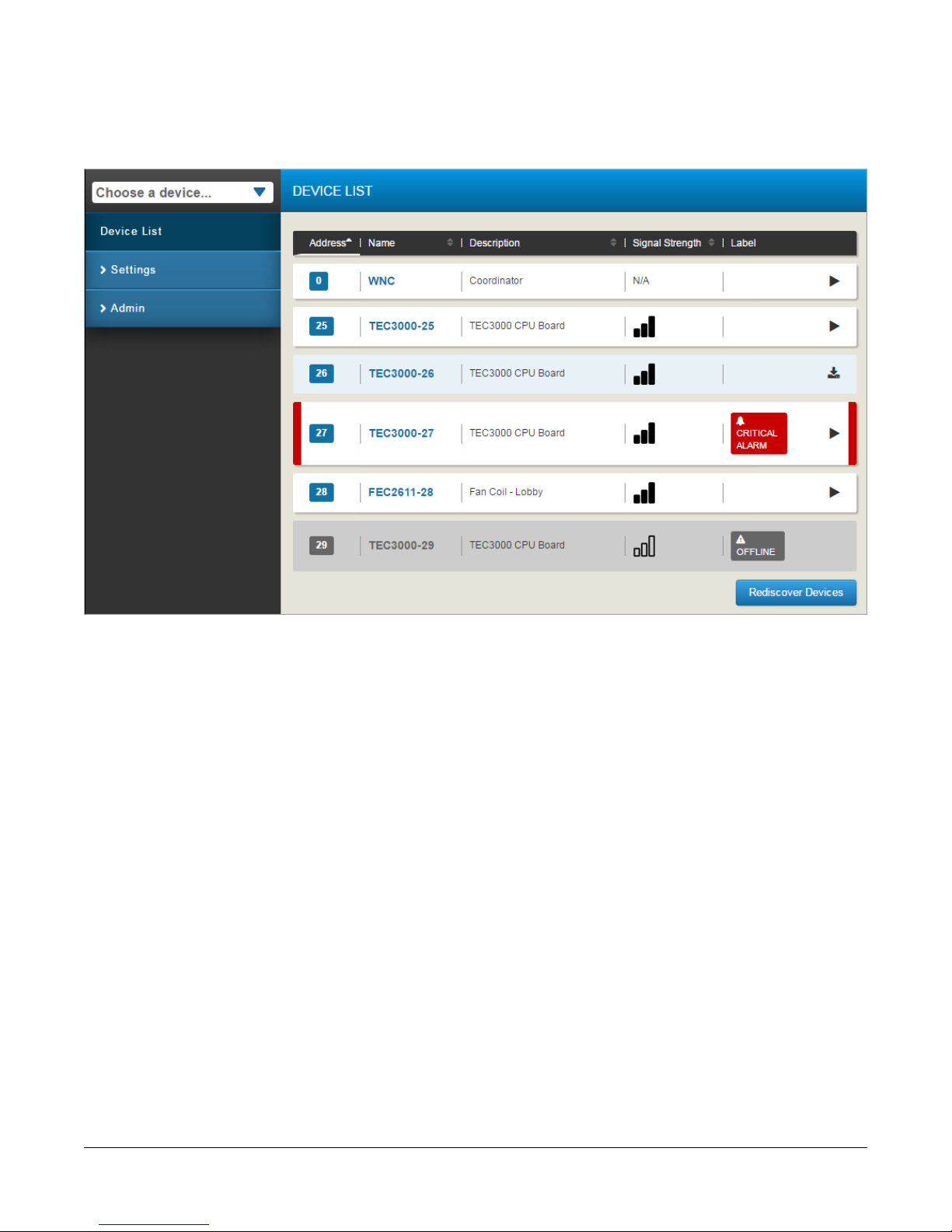
Figure 1: WNC Gateway UI
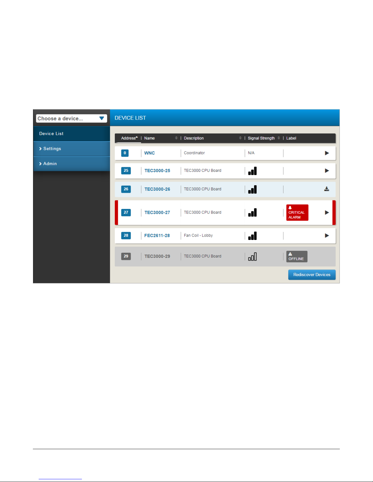
The WNC Gateway uses colored bars to indicate the condition of points and alarms (). These bars enable the user
to zero in on the most important statuses from a long list of devices or points. Points that are in an alarm status show
red bars at left and right sides of that point's entry in the list. Points that are overridden or Out of Service show orange
bars. Points that are Offline show black bars. Point values that are read-only show grey borders. These colors and
rules match the default indicators in Metasys systems.
3WNC1800 Wireless Network Coordinator Gateway User's Guide
Page 4
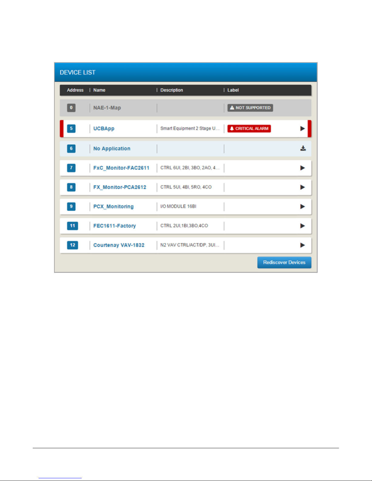
Figure 2: WNC Point Status Indicator Bars
Navigating in the WNC Gateway UI
When using the WNC Gateway through a web browser on a computer, as shown in Figure 3, you see the entire
user interface with the left side of the Gateway dedicated to menu selections and the right side dedicated to equipment
selections. The Device List, overall settings, and Admin Options can be selected and viewed or adjusted as you like.
When navigating to other menus, a menu button appears at the top of the list to allow you to return to the home
screen.
When viewing the WNC Gateway interface on a phone or mobile device, the screen displays either the menu
selections on the left or the equipment selections from the right. You can slide the screen left or right to see the
desired selections.
4WNC1800 Wireless Network Coordinator Gateway User's Guide
Page 5
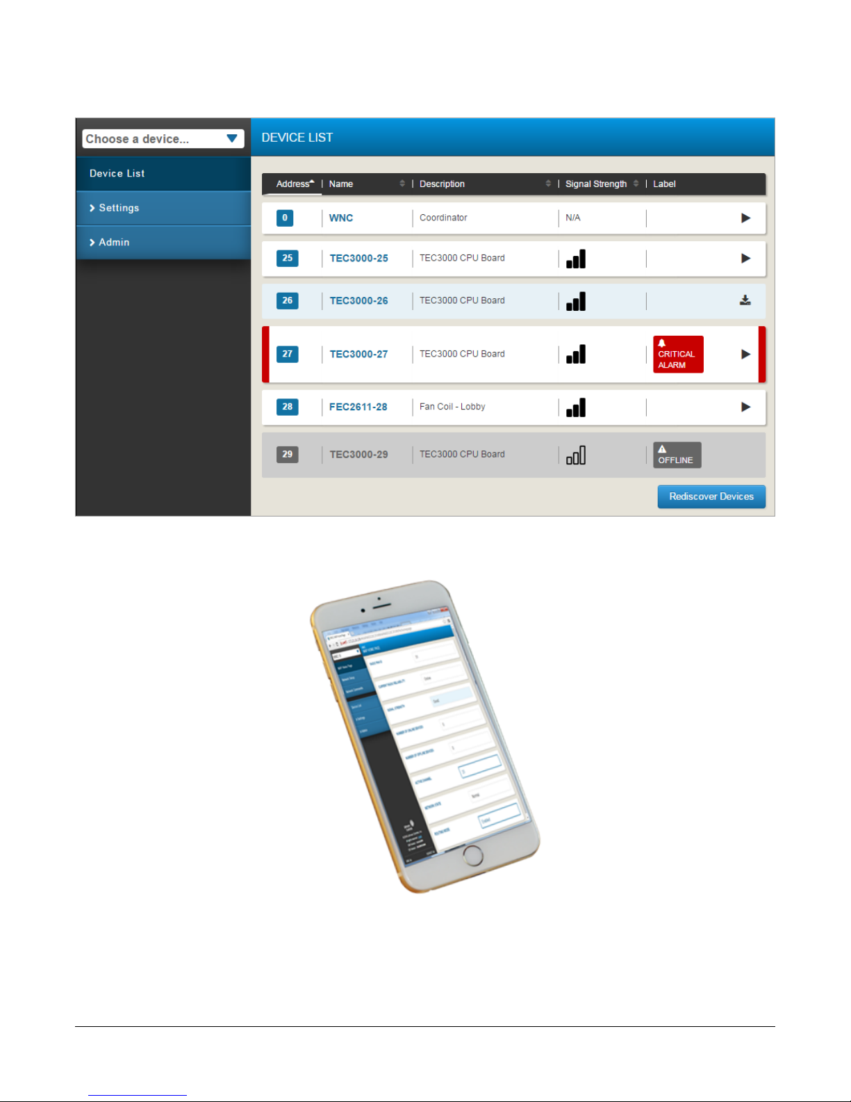
Figure 3: WNC Gateway UI on a Desktop
Figure 4: WNC Gateway UI on a Mobile Device
For information on WNC Gateway settings, see the WNC Gateway Settings section.
5WNC1800 Wireless Network Coordinator Gateway User's Guide
Page 6
Device List
When the WNC Gateway is connected to a network, it detects the devices on that network and populates the Device
List. You can select individual devices to view or command directly from the list or by using the Choose a device
drop-down list. Selecting a device takes you to that device's home page.
Devices will automatically appear in the device list when they join the network. It can take up to 10 minutes for a
device to appear the first time.
Figure 5: Device List ZigBee® Network
Note: Normally, using the Rediscover Devices button is not necessary, but may be required if alarms and status
indications do not self-clear, if firmware has been updated or new applications have been downloaded to
the controllers.
6WNC1800 Wireless Network Coordinator Gateway User's Guide
Page 7
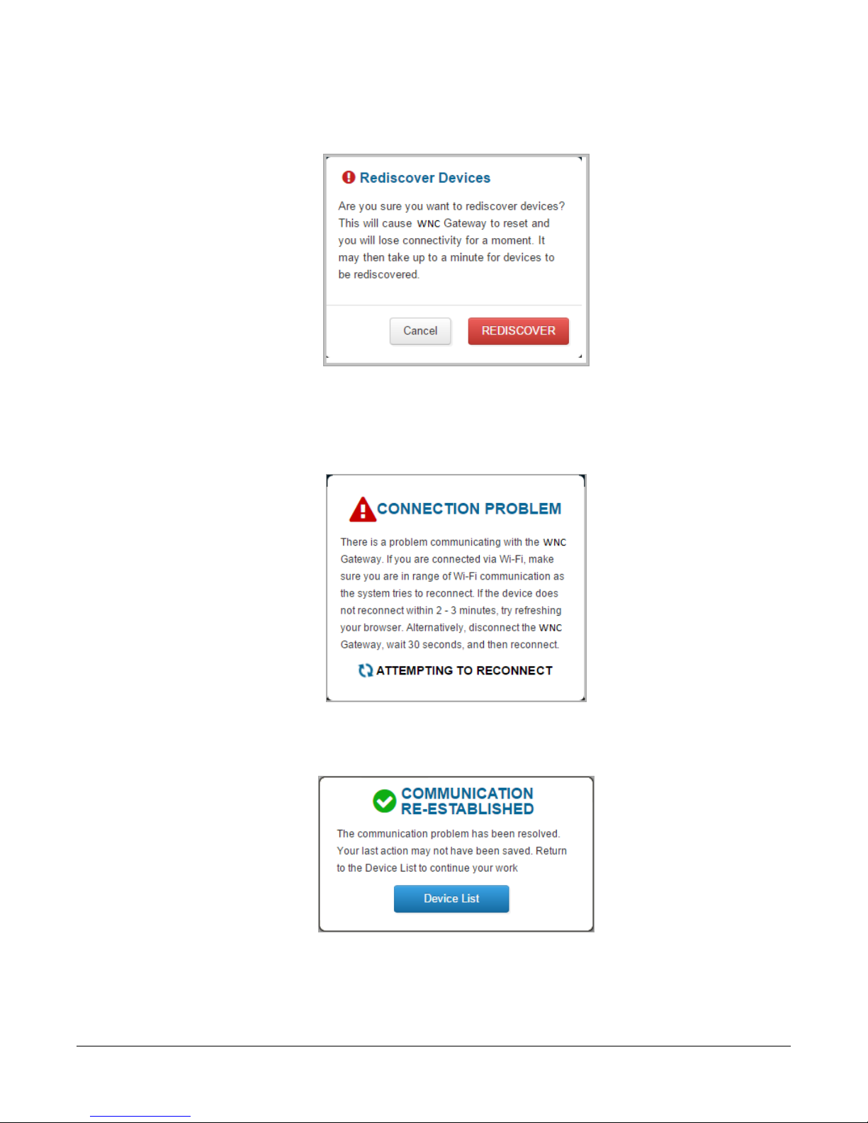
1. Click Rediscover Devices. The Rediscover Devices screen appears.
Figure 6: Rediscover Devices
2. Click Rediscover. The WNC Gateway shows a connection problem while the device reads the network. This is
a transitory condition and typically can be ignored.
Figure 7: Connection Problem
3. When communication is re-established, click Device List to return to the updated device list.
Figure 8: Communication Re-established
7WNC1800 Wireless Network Coordinator Gateway User's Guide
Page 8

Security
The WNC Gateway uses security certificates to authenticate itself to web browsers. Refer to the Mobile Access
Portal Gateway Network and IT Guidance Technical Bulletin (LIT-12012015) for information on installing and using
security certificates.
The first time you log in to the WNC Gateway, the Change Password and Passphrase webpage appears. You must
change the Admin password and Wi-Fi passphrase. WNC Gateway, passwords must have at least eight characters,
at least one digit (0–9), and one upper case letter (A–Z). The Wi-Fi access point passphrase must have at least
eight characters but there are no other restrictions.
Following these simple rules to add complexity to your password:
• Use a password that is at least eight (8) characters in length (and preferably even longer than eight characters).
• Do not use dictionary words in your password.
• Use uppercase and lowercase letters.
• Use numbers.
• Use symbols such as $, %, &.
If you forget the Admin password, the WNC can be reset to the factory password that is located in the original
Quickstart Guide. For this reason, you should maintain physical security of the Wireless Network Coordinator Quick
Start Guide (Part No. 24-10737-105) with the passphrase on it to discourage unauthorized attempts to access
equipment.
User Roles
User roles define access levels in WNC Gateway and network functions to the level appropriate for a user's job
requirements. The user roles available are Admin, Technician, and Tenant.
Access to the WNC Gateway setting options are controlled by user level.
Table 1: Settings Access by User Role
Wi-Fi Access Point
Gateway.
Ethernet
stationary device or being used as a BACnet router for a
supervisor.
About
Gateway.
Diagnostics
provide to Product Support (for product support only).
BACnet Time Sync
viewed. Because the WNC Gateway does not have a battery
to maintain time during a power failure, you should make
sure that time is in sync after a device reset to apply correct
times to the system logs. Remote users should be aware
that no time zone information persists if your browser time
is different from the local time for the WNC Gateway.
User RoleUse toSetting
Admin, Tech, and TenantChange Wi-Fi SSID and Wi-Fi Passphrase on WNC
Note: Tenants can view but not change
Wi-Fi settings.
Admin and TechConfigure Ethernet settings if using WNC Gateway as a
AdminInstall security certificate and private key.SSL
Admin and TechUpdate the software version of the WNC Gateway.Software Updates
AdminAdd or delete users and define their user roles.Admin
Admin, Tech, and TenantLists the versions of the software components used in WNC
AdminDownload a compressed file of diagnostic information to
AdminDownload a text file of user actions on the WNC Gateway.Audit Log
Admin and TechSet the time on the WNC Gateway and the device being
8WNC1800 Wireless Network Coordinator Gateway User's Guide
Page 9
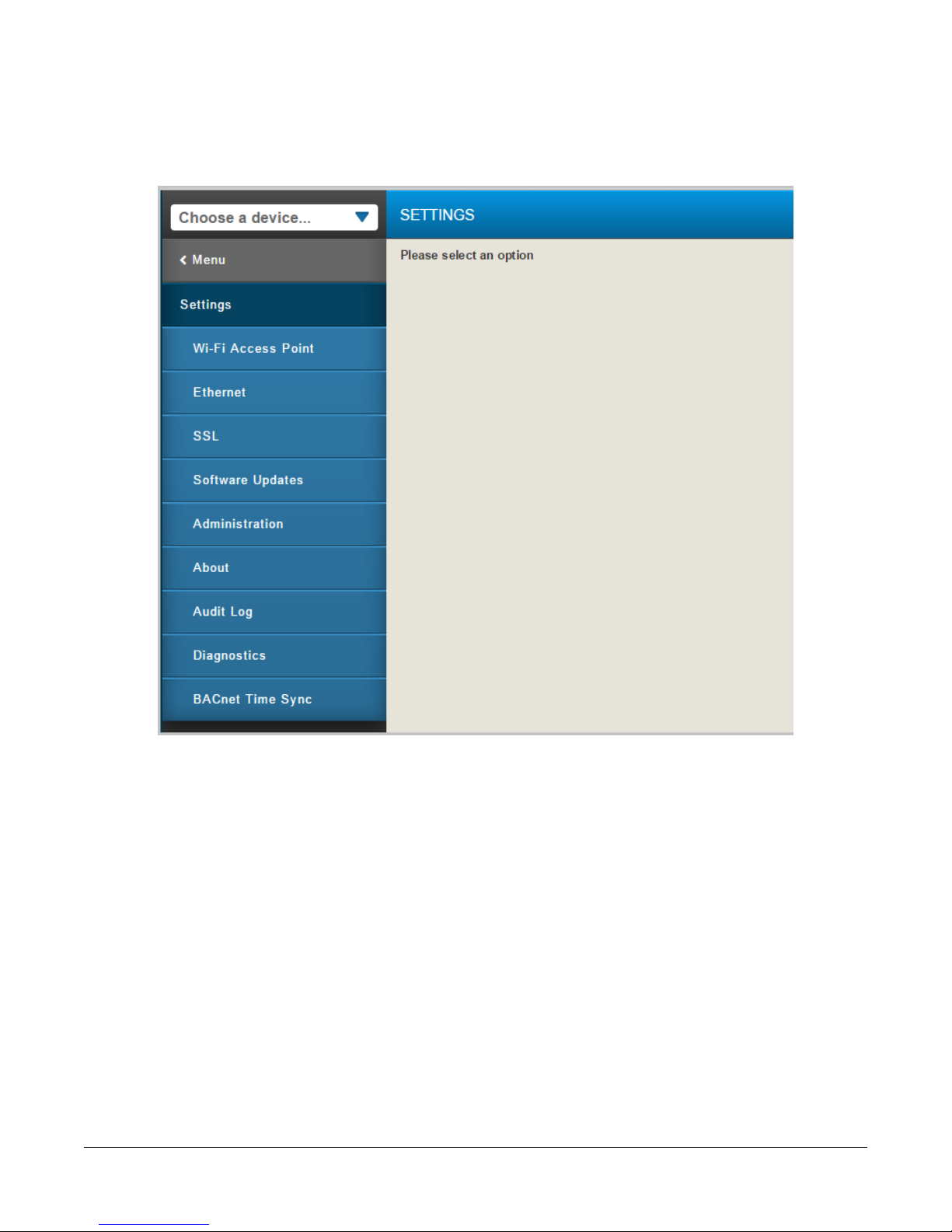
WNC Gateway Settings
This section describes how to adjust the settings of the WNC Gateway according to user level.
Figure 9: WNC Gateway Settings Menu (Administrator)
9WNC1800 Wireless Network Coordinator Gateway User's Guide
Page 10
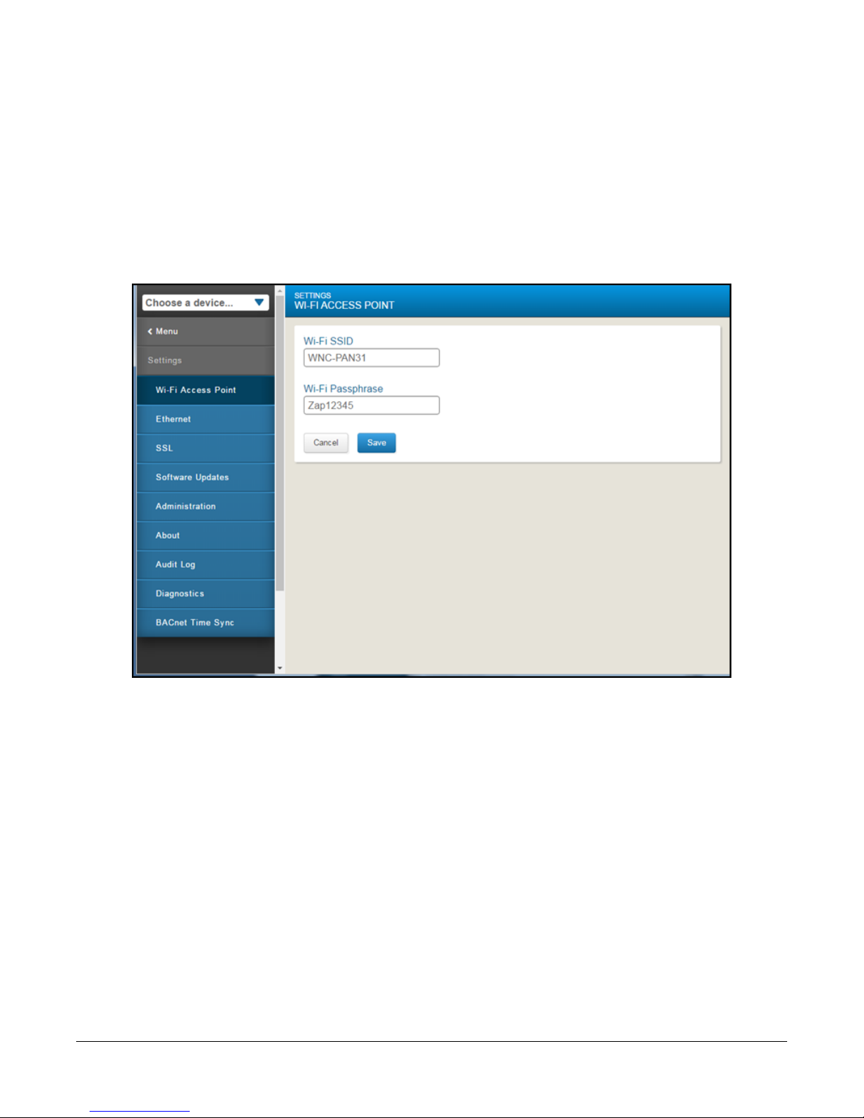
Wi-Fi Access Point Settings
The WNC Gateway acts as an access point for connecting Wi-Fi devices such as cell phones, tablets, and laptops
to your field controllers, wireless thermostats, and rooftop units on a building management network. All Admin and
Tech users can change the Wi-Fi SSID and the Wi-Fi Passphrase fields under the Wi-Fi Access Point settings (Figure
10). The default settings for these two fields are included in the Wireless Network Coordinator Gateway Quick Start
Guide (Part No. 24-10737-105) , which ships with each WNC1800 Gateway. To access the Wi-Fi settings, click
Wi-Fi Access Point in the Settings menu on the WNC Gateway UI. The first time you log in to the WNC Gateway,
the system prompts you to change the Wi-Fi Passphrase. The Passphrase must be a minimum of eight characters.
For more information on setting a secure password see Security.
Figure 10: Wi-Fi Access Point Settings Screen
Note: The Wi-Fi Access Point cannot be disabled.
10WNC1800 Wireless Network Coordinator Gateway User's Guide
Page 11
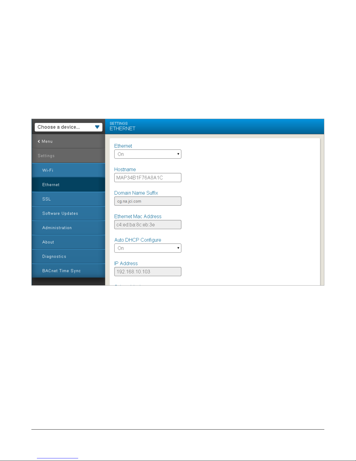
Ethernet Settings
Access the Ethernet Settings screen from the Settings Menu when logged in as either an Admin or Tech user.
Notes:
• If you are using Ethernet, you must have the WNC Gateway plugged into external power before connecting the
coordinator.
• Changes to these parameters will take effect immediately, but it can take up to 5 minutes before they are persisted
in the WNC1800’s archive. If power is cycled before the archive occurs, the changes will be lost.
For more information on committing changes, see WNC Network Setup.
Figure 11: WNC Gateway Ethernet Settings Screen
Note: A grey field is read-only; a white field can be edited.
11WNC1800 Wireless Network Coordinator Gateway User's Guide
Page 12

Table 2: Ethernet Setting Screen Descriptions
Hostname
Domain Name Suffix
Ethernet Mac Address
WNC followed by the
wireless WNC address.
OnAuto DHCP Configure
OffAuto DNS Configure
DescriptionDefaultSetting
Must be turned on to connect to an NAE.Must be OnEthernet
Hostname is a unique name for this device on a WNC or an Ethernet
network. The user can modify the Hostname.
The last part of a domain name. Domain name suffixes include .com, .net,
and .org, among others.
A MAC (media access control) address is manufactured into all network
cards, including Ethernet and Wi-Fi devices. It uniquely identifies hardware
on a WNC or an Ethernet network.
Determines whether to automatically configure a DHCP address. Turn off
to use your WNC1800 Gateway with a static IP address. Contact your IT
Department to obtain necessary settings if you wish to manually set
addresses.
Used to set Address if Auto DHCP Config is OFF.IP Address
Used to set Mask if Auto DHCP Config is OFF.255.255.255.0Subnet Mask
Used to set Default Gateway if Auto DHCP Config is OFF.Default Gateway
If you have a Dynamic Name Server (DNS) on your network, the WNC1800
Gateway can be accessed by a unique name instead of an IP address.
Set this field to ON to enable use of the DNS.
Address of your Primary DNS server, if available.Primary DNS Server
Address of your Secondary DNS server, if available.Secondary DNS Server
Note: The WNC Gateway User Interface uses https secure protocol. To externally access the WNC Gateway you
need to open port 443. Contact the site's IT department for more information.
12WNC1800 Wireless Network Coordinator Gateway User's Guide
Page 13
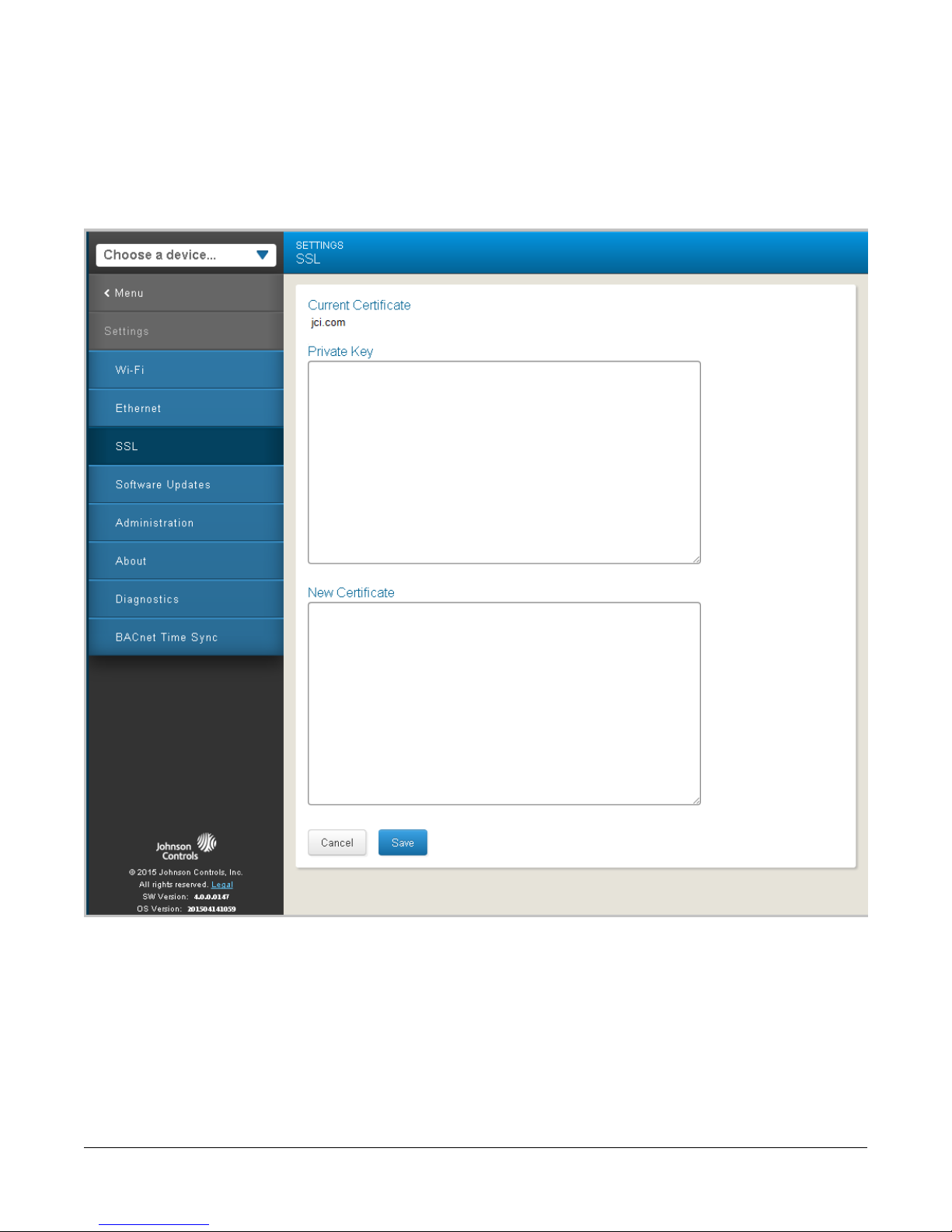
SSL Settings
The SSL Settings screen shows the currently installed security certificate (if any) and allows you to install both a
Private Key and a new certificate. The following procedure can only be performed by an Admin user. Refer to the
Mobile Access Portal Gateway Network and IT Guidance Technical Bulletin (LIT-12012015) for information on how
to use SSL Certificates in a WNC Gateway.
Figure 12: WNG Gateway SSL Settings Screen
13WNC1800 Wireless Network Coordinator Gateway User's Guide
Page 14
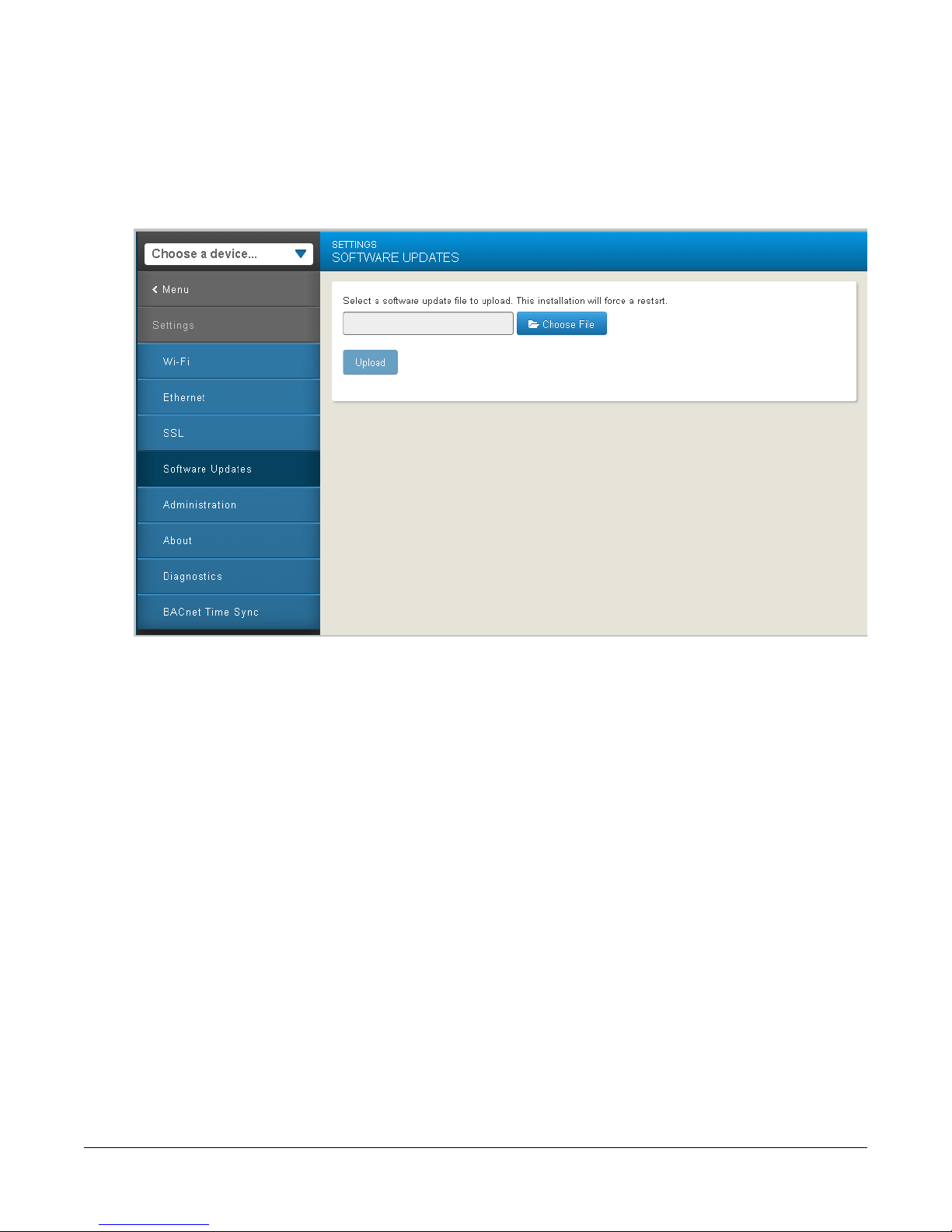
Updating WNC1800 Gateway Software
The following procedure can only be performed by an Admin or Tech user.
1. On the Settings menu, select Software Updates and click Choose File to navigate to the location of the new
software image.
Figure 13: Software Updates Screen
2. Click Upload to transfer the file into the WNC Gateway.
3. Click the Upload button to have WNC Gateway use the new file.
4. The WNC Gateway goes offline temporarily while the updates are applied, during which time you may see a
Connection Problem message.
5. The WNC Gateway will also update the firmware of the attached ZFR Coordinator, if needed.
14WNC1800 Wireless Network Coordinator Gateway User's Guide
Page 15
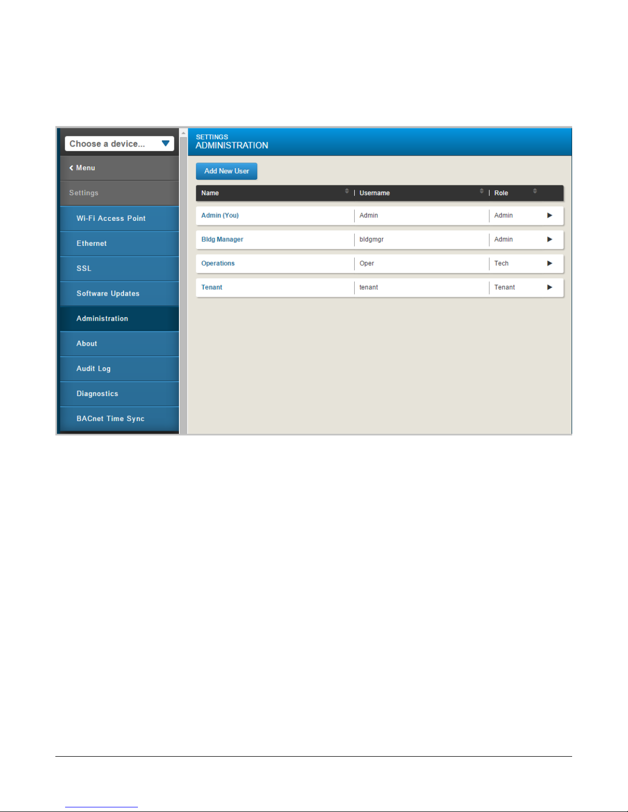
Administration Settings
The Administration Settings screen can only be viewed by an Admin User. On this screen, an administrator can add
or delete users, define user roles, and change passwords.
Figure 14: Administration Settings Screen
15WNC1800 Wireless Network Coordinator Gateway User's Guide
Page 16
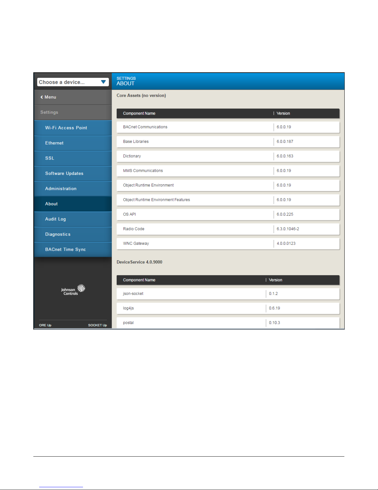
About Screen
The About screen can be viewed by any user and shows the versions of the various software components that make
up the WNC Gateway software.
Figure 15: About Screen Settings
16WNC1800 Wireless Network Coordinator Gateway User's Guide
Page 17

Audit Log
The Audit Log feature allows an Admin user to download and view a log of user actions on the WNC Gateway. When
you select download, a text file containing entries for the following events is created.
• Add new user
• Unrecoverable startup error
• Delete user
• Pushbutton reset 1
• Pushbutton reset 2
• System preferences changed
• Time changed (recorded only when done via BACNet Time Sync feature)
• User command (records commanded value, nothing about success or failure)
• User logged out due to inactivity
• User login failure
• User login success
• User logout
• User password changed
The log entry format contains (when available and applicable) the date, time, device name, timestamp, process
name (process ID), and a message describing each event. The log is not cleared through software updates or factory
resets of the WNC Gateway.
Note: If a power failure occurs, the time and date stamp are not persisted and need to be set; therefore, some of
the log entries may not have an accurate date and time stamp (for example, if the device lost its time setting
from a power failure).
For information on how to create an Audit Log, see Appendix: Creating an Audit Log.
17WNC1800 Wireless Network Coordinator Gateway User's Guide
Page 18

Diagnostics
The Diagnostics screen provides a method for product support personnel to access diagnostic information.
Figure 16: Diagnostics Screen
18WNC1800 Wireless Network Coordinator Gateway User's Guide
Page 19

BACnet Time Sync
BACnet Time Sync allows you to set the time on the WNC Gateway and its discovered wireless devices. The time
and date default to the computer's time and date, but you can change the time and date by clicking either the calendar
or clock icon, as shown in Figure 17. Because the WNC Gateway does not have a battery backup for the internal
clock, you must synchronize the time and date after the WNC Gateway is reset or loses power to ensure that the
system logs have the correct time and date information.
Figure 17: BACnet Time Sync
19WNC1800 Wireless Network Coordinator Gateway User's Guide
Page 20

WNC Gateway Device
WNC Home Page
The WNC Home Page shows you information about the ZFR network. This information can be used to see the
overall status of the devices on the network.
Figure 18: WNC Home Page
Table 3: WNC Home Page Descriptions
DescriptionItem
Displays the physical RF PAN (Personal Area Network) ID for your network.Radio PAN ID
Displays the status of the radios in your network.Current Radio Reliability
Displays the signal strength of the radios in your network.Signal Strength
Displays the number of current devices in your network that are online.Number of Online Devices
Displays the number of current devices in your network that are offline.Number of Offline Devices
Active Channel
Displays the physical RF channel number for your network. Typical channels for North
America are 15, 20, and 25. Channels 11 to 26 may be entered if the Allow Extended Channel
List is set to TRUE on the Network Setup page.
Notes:
• Channel 26 will not be accepted for some countries (including the US).
• Maximum Active Channel = 25.
Displays the network protocol type in use by the network.Network State
Displays if BACnet routing is Enabled or Disabled.Routing Mode
20WNC1800 Wireless Network Coordinator Gateway User's Guide
Page 21

WNC Network Setup
The Network Setup page allows you to configure the WNC's BACnet router settings. These settings are required to
communicate with an NAE or other BACnet IP devices on the Ethernet port.
Figure 19: Network Setup Page
Note: The Wireless Field Bus Network Address is a unique BACnet Network Address.
Table 4: Network Setup
DescriptionDefaultSetting
Routing must be enabled in order for the WNC to act as a BACnet IP router.EnabledEnable / Disable
Routing
BACnet Device
Object Identifier
47808BACnet IP Port
1001BACnet IP
Network Address
ID needs to be unique to the site.
Notes:
• There is no validation that this value is unused by another device and therefore
available.
• A BACnet ID of 4194303 is a reserved value and should not used.
This value must match the value set in the Supervisory Controller. Typically does not
change.
This value must match the value set in the Supervisory Controller. Typically does not
change.
21WNC1800 Wireless Network Coordinator Gateway User's Guide
Page 22

Table 4: Network Setup
DescriptionDefaultSetting
Wireless Field
Bus Network
Address
FalseCommit Changes
and Reset
This is the Field Bus Network Address that uniquely identifies the network on the wireless
side of the WNC router. All WNC and other BACnet routers must have a unique value.
One recommendation is to use the PAN ID of the connected ZFR Pro Coordinator Radio,
which also must be site-specific.
Note: There is no validation that this value is unused by another device and therefore
available.
When any of the values have been changed, set this to TRUE, which causes the WNC
to accept the values. The WNC will reset after the changes have been accepted.
Note: Any time the WNC Resets, it can take up to 15 minutes before all wireless devices
are rediscovered and online at a supervisory controller.
Bring Up the Field Controllers on Your Network
With all devices powered on and communication occurring with the WNC Gateway and the Coordinator, the Number
of Online Devices field should start to increment up until it matches the number of wireless devices on your network.
Figure 20: WNC Field Controller Increment
If this is a Stand-alone Network
If the number of online devices shown on the WNC Home Page increments up to the correct number, you may now
view and edit the settings on the connected devices by accessing them through the Device List. See Device List for
more information.
22WNC1800 Wireless Network Coordinator Gateway User's Guide
Page 23

If this Network is Controlled by a Supervisory Controller
If you are on a larger network controlled by a Supervisory Controller, there are additional steps to perform. When
the devices are online and communicating with the WNC1800Gateway, you need to log on to the Supervisory
Controller and add the remote field bus and all the field devices that are connected to a new Remote Field Bus
Trunk. The WNC1800 Gateway acts as a BACnet router, which can be accessed using the Remote Field Bus Feature
of Network Automation Engines (NAE). This cannot be used with NCEs since they do not support Remote Field
Bus.
Note: If using a Supervisory Controller, the Routing Mode field on the WNC Home Page must be set to Enabled.
On the WNC Network Setup Screen the Enable/Disable Routing field must also be set to Enabled.
Add the WNC1800 Gateway to the Supervisory Controller as a Remote Field Bus trunk.
•
Log into the Metasys UI.
• On the Insert menu select Insert Integration.
• Choose Field Bus MSTP for integration type.
• An NAE that has two wired MS/TP trunks. The wireless Trunk Number will be given a number of 3 or higher.
Subsequent remote field busses will use sequential numbers (4, 5, 6).
• The unique Network Address number should match the number defined in the WNC Network Setup Screen.
Add the devices on the WNC1800 Gateway Remote Field Bus trunk.
• Use the Auto Discovery Utility in Metasy to find the devices attached to the WNC1800.
• The number of devices should match the Number of Online devices field on the WNC Home Page.
Using BBMD to Communicate Across Multiple Subnets
If you have devices shown on the WNC1800 Gateway but the NAE does not discover them, they may be on another
subnet. If devices are on another subnet, you may need to set up a BBMD object in order to communicate with them.
A way to check this is to look at the IP addresses of the WNC Gateway and the Supervisory Controller you are trying
to join. For example, the first three octets of the IP address should be the same. If they are not, then the devices
are on different subnets and you need a BBMD object to properly route messages across the subnets.
Refer to the MS/TP Communications Bus Technical Bulletin (LIT-12011034) for more information on Remote Field
Bus. It may be necessary to discuss these settings with your IT Administrator if the WNC Gateway and the Supervisory
Controller are on different network broadcast domains that require the addition of a BBMD object.
23WNC1800 Wireless Network Coordinator Gateway User's Guide
Page 24

Figure 21: WNC Broadcast Disabled
In the WNC Gateway UI, select the BBMD screen and set the Broadcast Disabled field to False. The Address-IP
field should be set to the IP address of the Supervisory Controller, which contains the BBMD object. In the case of
multiple controllers on the same network, only one will have the BBMD object. See WNC BBMD for more information.
24WNC1800 Wireless Network Coordinator Gateway User's Guide
Page 25

WNC BBMD
The BBMD Page allows you to configure the WNC's BACnet Broadcast Management Device (BBMD) settings. These
settings are required to communicate with an NAE or other BACnet IP device on a different subnet, because most
IP Routers block broadcast messages that are used in the BACnet system.
Notes:
• BBMD setup is only required if the NAE and WNC are on different IP subnets.
• Changes to these parameters will take effect immediately, but it can take up to 5 minutes before they are persisted
in the WNC’s archive. If power is cycled before the archive occurs, the changes will be lost.
• If the network number is changed on the NAE, the NAE may need to be reset for it to take effect (after the network
number is matched in the WNC).
Figure 22: WNC BBMD page
Table 5: WNC BBMD Descriptions
Address IP
DescriptionDefaultSetting
FalseBroadcast Disabled
47808Address-UDP Port
Setting the Broadcast Disabled to False
will enable the BBMD. The BBMD should
not be enabled until the other values on
this page have been configured.
Set to the IP Address of the associated
NAE.
This value must match the BACnet IP Port
set in the Network Setup and typically
does not change.
Do not change.255.255.255.255IP Broadcast Mask
25WNC1800 Wireless Network Coordinator Gateway User's Guide
Page 26

WNC Gateway Network Commands
The Network Commands page allows you to broadcast commands to devices on the ZFR Pro network. These
commands can be used to improve the wireless communications by Optimizing the Network or by performing a
Network Reform.
Optimizing the Network
The devices on a ZFR Pro network automatically find new routes (paths) when a message fails. However, these
paths may not be optimal due to how the devices were brought online.
The Optimize Network command sends a command to all of the devices on the ZFR Pro network to clear their
routing tables, causing the devices to establish new optimal routes. This command can be useful after a network
has been established and to lessen the number of hops between a controller and the coordinator.
When optimizing the network, the ZFR Pro Coordinator Radio clears its internal routing tables and initiates a relearn
sequence to all ZFR Pro Routers. During the relearn sequence, the ZFR Pro Routers also clear their routing tables
and attempt to find better signal paths to the ZFR Pro Coordinator Radio.
Network Reform
If you have problems with controllers or sensors joining the wireless network, or notice problems with devices staying
offline, a Network Reform may help.
These problems occur because during network installation, wireless address distribution can be fragmented due to
wireless nodes being powered up in random order. When the Network Reform command is performed, all wireless
network addresses are cleared and redistributed, providing optimum network performance and non-duplicate wireless
short addresses.
Figure 23: WNC Gateway Network Commands Page
Note: If you select False and then Save, the command will still be issued, so AlwaysuseCancelrather thanSave
to abort any selection.
26WNC1800 Wireless Network Coordinator Gateway User's Guide
Page 27

Commanding Points in WNC Gateway
Commands allow you to change a point's value. For example, you can adjust the value of a fan to ON or OFF to
make the fan run or stop. You can also override setpoints, offsets, time delays, and many other points depending
on the controller or application to which you are connected. In the WNC Gateway user interface, points that are
commandable or adjustable are outlined in blue. Points that are not commandable are outlined in light grey.
In the Parameters screen below, you can command the MINFLOWCO2-SP to a different value by left-clicking inside
the blue box next to the setting.
Note: Values can also be changes on the NAE Supervisor.
Figure 24: Parameters Screen
27WNC1800 Wireless Network Coordinator Gateway User's Guide
Page 28

To command the MINFLOWCO2-SP to a different value, click the field next to it (outlined in blue). The screen for
commanding that field appears as in the figure below. In this case, you select Change Default Value from the
drop-down list and use the up and down arrows to change to a valid temperature that you want to use. The range
of valid temperatures is shown below the field. When you are satisfied, click Save. Different types of points have
different adjustments that can be applied.
Figure 25: CV Occupied Cooling Setpoint Command Screen
Note: Pressing the Priority Array button allows you to see all the active values in the Priority Array.
28WNC1800 Wireless Network Coordinator Gateway User's Guide
Page 29

TEC3000 Wireless Thermostat Controllers
The figures in this section are representative of how the display appears in the WNC Gateway User Interface. For
more information on the TEC3000, refer to the TEC3000 Series Stand-Alone and Field-Selectable BACnet MS/TP
or N2 Networked Thermostat Controllers Technical Bulletin (LIT-12011956).
Figure 26: TEC Wireless Thermostat Controller Home Page
29WNC1800 Wireless Network Coordinator Gateway User's Guide
Page 30

TEC3000 Setpoints
When you choose a TEC3000 from the device list and navigate to the setpoints screen as shown below, you have
access to user configurable setpoints. If the value field for a setpoint is outlined in blue, you may edit it by selecting
the field and making the changes you like.
Figure 27: TEC Setpoints Screen
30WNC1800 Wireless Network Coordinator Gateway User's Guide
Page 31

TEC3000 Schedules
You can view and edit schedules on the TEC3000 from the Schedule screen. When you click Settings, you are
presented with Set Schedule and Schedule Options selections, as shown below.
Figure 28: TEC3000 Schedule Options
Use the Set Schedule menus to view current or weekly schedules, enable schedules, and to add or edit existing
schedules.
Figure 29: TEC3000 Set Schedule Screen
Clicking the arrow next to a schedule parameter opens the schedule detail for that day and time. Edit as you like
and click Save.
31WNC1800 Wireless Network Coordinator Gateway User's Guide
Page 32

Figure 30: TEC3000 Schedule Detail
Use the Schedule Options menu to set specific features of the TEC3000 schedule, such as Optimal Start Enable
and the duration of the Motion Sensor Timeout.
Figure 31: TEC3000 Schedule Options
32WNC1800 Wireless Network Coordinator Gateway User's Guide
Page 33

TEC3000 Display Settings
The TEC3000 has a configurable display. The onboard display settings can be configured through the WNC Gateway.
Figure 32: TEC3000 Display Settings
33WNC1800 Wireless Network Coordinator Gateway User's Guide
Page 34

TEC3000 Control Setup
The operation of the TEC3000 controller is configured on the Control Setup page in WNC Gateway.
Figure 33: TEC3000 Control Setup Screen
34WNC1800 Wireless Network Coordinator Gateway User's Guide
Page 35

TEC3000 Network Setup
The Network Setup page allows you to configure the TEC3000 network settings. See TEC Series Wireless Thermostat
Controller System Technical Bulletin (LIT-12011414) for the applicable settings.
Figure 34: TEC3000 Network Setup Screen
Table 6: TEC3000 Network Setup Screen Descriptions
DescriptionMenu Parameter
Wireless Field Bus. This is a read-only value. TEC300 cannot set MS/TP or BACnet wireless.FC Comm Mode
BACnet Instance ID
BACnet Device Address
BACnet Encoding Type
PAN ID
This is the instance ID of the device on the BACnet bus. BACnet systems use the instance
ID for identification of the device. It can be set from 1 to 4,194,303.
Note: This must be unique to this device across the entire BACnet system.
This is the physical MAC address of the BACnet device on the wireless PAN. It can be set
from 4 to 127. Two devices on the same bus cannot have the same BACnet device address.
This is the method of data encoding and is used by the BACnet bus. The default value, ISO
10646 (UCS-2), is the encoding used by the Metasys platform. When operating on a
third-party BAS, refer to the documentation provided with the BAS for the proper encoding
type and is used for BACnet communications.
This is the PAN ID of the ZFR network. Do not change from the WNC or the device will
remove itself from the current PAN and you will need to physically go to the TEC and set
it back.
35WNC1800 Wireless Network Coordinator Gateway User's Guide
Page 36

TEC3000 Equipment Setup
Figure 35: TEC3000 Equipment Setup Screen
36WNC1800 Wireless Network Coordinator Gateway User's Guide
Page 37

TEC3000 System Status
TEC3000 System status can be viewed at the WNC1800 Gateway. Since it is viewing current conditions, the values
are not editable.
Figure 36: TEC3000 System Status
37WNC1800 Wireless Network Coordinator Gateway User's Guide
Page 38

TEC3000 Control Status
The TEC3000 Control Status page shows the status of settings currently set through the setup menus. These
statuses are view-only.
Figure 37: TEC3000 Controller Status Page
38WNC1800 Wireless Network Coordinator Gateway User's Guide
Page 39

TEC3000 Controller Info Page
The TEC3000 Controller Info Page provides the model number and software version of the TEC3000 that you are
viewing. You can also change the name of the controller to a name that is descriptive for your location on this screen.
Figure 38: TEC3000 Controller Info Screen
Notes:
• Many browsers use UTF-8 character encoding specifically for foreign languags; however, the TEC does not.
Unexpected results can occur if using non-ASCII characters in the strings written to a TEC or other controllers
that do not support UTF-8.
• When changing or updating strings, it is generally safer to delete the strings and re-enter them. If this is not done
in this way, some unexpected results can occur.
• Strings with leading or trailing white space characters (in the following instances, space or tab) will be stripped.
• The WNC will indicate an error if the Device Name field:
the name begins with a space-
- the name contains all space characters
39WNC1800 Wireless Network Coordinator Gateway User's Guide
Page 40

Field Controllers
The WNC Gateway can discover, read, and display data and alarms from Field Controllers, set schedules, view
trend point data, and command points for selected controllers.. Depending on the capabilities of each controller
family, the WNC Gateway can have the information use the CCT to configure how the information is displayed.
FEC Controller Home Screen
The points that appear on the home page are defined by the Display Configuration Feature in the Control Configuration
Tool. Fields outlined in blue can be edited. For information on how to use the Display Configuration Application,
refer to Configuring the Local Controller Display in the Controller Tool Help (LIT-12011147).
Figure 39: FxC Controller Home Page
40WNC1800 Wireless Network Coordinator Gateway User's Guide
Page 41

Advanced Application Field Controllers (FAC and PCA) Home Screen
The points that appear on the home page are defined by the Display Configuration Feature in the Controller
Configuration Tool. In the example below, the home page was configured to show the inputs and outputs for analog
and binary points. Fields outlined in blue can be edited. For information on how to use the Display Configuration
Application, refer to Configuring the Local Controller Display in the Controller Tool Help (LIT-12011147).
Figure 40: FAC Home Page
41WNC1800 Wireless Network Coordinator Gateway User's Guide
Page 42

FAC and PCA Controller Inputs
FACs and PCAs have default views of inputs to the device. Fields outlined in blue can be edited through the WNC
Gateway.
Figure 41: FAC Inputs Screen
FAC and PCA Controller Outputs Screen
FACs and PCAs have default views of Outputs to the device. Fields outlined in blue can be edited.
Figure 42: FAC and PCA Controller Outputs
42WNC1800 Wireless Network Coordinator Gateway User's Guide
Page 43

FAC and PCA Controller Parameters
FACs and PCAs have default views of the parameters of the device. Fields outlined in blue can be edited.
Figure 43: FAC and PCA Controller Parameters
43WNC1800 Wireless Network Coordinator Gateway User's Guide
Page 44

FAC and PCA Controller Events Page
The WNC1800 Gateway logs changes to the FAC and PCA Controllers on the events page. The events log can be
sorted by any column heading so that you may find what you are looking for quickly.
Figure 44: FAC and PCA Controller Events Screen
44WNC1800 Wireless Network Coordinator Gateway User's Guide
Page 45

Configuration Tool
Field Controllers use the Configuration Tool (CCT or PCT) to configure content displayed for the WNC Gateway.
You can configure the display after you select the hardware in the Hardware Definition Wizard of the Configuration
Tool. Once a display is configured for and downloaded to a controller, WNC Gateway is able to use the configuration
data to determine what information it shows for that controller. CCT is required to build Display profiles that are in
turn used by the WNC Gateway to display data in its UI. If any changes have been made to the Gateway, perform
a Rediscovery on the WNC is required for those changes to appear.
Note: The default controller setting of the CCT divides configured points into generic sections of Input, Output, and
Miscellaneous. These sections do not always match what is shown in the WNC Gateway. Therefore, some
points displayed in the Inputs list in the CCT may show up in the Parameter Category in the WNC Gateway.
However, you may use a custom display object in the CCT to define how the groupings of points appear in
the WNC1800 Gateway.
For more information on how to define CCT, see Control Tool Help. (LIT-12011147)
Display Configuration
Use a custom display object to determine how information displays in the WNC1800 Gateway UI.
For the WNC Gateway, the Display tab allows you to:
• define which folders and points appear on the home page
• define the order and groupings of folders and points on the home page
• edit point user names and descriptions using the Mass Edit feature
After you configure the display, download the application to the controller, and then click Rediscover Devices in
the WNC Gateway Device List page. WNC Gateway is refreshed and reads the new display information.
45WNC1800 Wireless Network Coordinator Gateway User's Guide
Page 46

Troubleshooting
Table 7: Troubleshooting
Error message Error Occurred Loading
Device Navigation in the left menu and
on the top of the home page.
Alarms on point is not being displayed
in the WNC Gateway
Some points displayed in the Inputs list
in the CCT may show up in the
Parameter Category in the WNC
Gateway.
Error message Error Saving SSL
Settings appears.
This occurs if you are selecting options on
the device or control screens on the
WNC1800.
If a Disable Alarms command is issued for
a point in the system, the WNC Gateway
will not report alarms for that point. There
is no indication in WNC Gateway that the
command was issued and there is no way
to enable alarms in a WNC Gateway for
the point.
CCT has default categories of Input,
Output, and Miscellaneous.
When an SSL key or certificate is very
corrupted, the SSL page detects it and
alerts you to the corrupted key or
certificate.
However, if the corruption is minor, for
example, an extra space was copied while
installing the certificate or a character was
missed, the UI does not detect the
problem and allows the corrupted key or
certificate to be saved. The server detects
the error and returns the Error Saving
SSL Settings message. While this
properly prevents the bad key or certificate
from being used, it does not inform you as
to the source of the problem.
RemedyCauseError message or condition
Wait a few moments and try again; and
the navigation should load correctly. This
does not seem to be an issue if the view
definition is removed from the WNC
Gateway.
At this time, there is no workaround for
this issue.
At this time, there is no workaround for
this issue.
Reinstall the SSL Key or Certificate as
described in the Mobile Access Portal
Gateway Network and IT Guidance
Technical Bulletin (LIT-12012015).
Related Documentation
Table 8: Related Documentation
Getting up and running quickly with the WNC
Gateway
Installing and Wiring WNC Gateway
WNC1800 Gateway Features, Benefits, and FAQs
WNC1800 Gateway Ordering Information
Working with Security Certificates
How to use Controller Tool (CCT or PCT) software
TEC3000 Series Thermostat Controllers
See Document:For Information On:
Wireless Network Coordinator Gateway, Quick Start Guide (Part No.
24-10737-105)
ZFR1820/ZFR1823 Wireless Field Bus Coordinator Installation
Instructions (Part No. 24-10737-96)
WNC1800/ZFR182x Pro Series Wireless Field Bus System Product
Bulletin (LIT-12012320)
ZFR Pro Wireless Field Bus System Product Bulletin (LIT-12012320)
Mobile Access Portal Gateway Network and IT Guidance Technical
Bulletin (LIT-12012015)
Controller Tool Help (LIT-12011147)
TEC3000 Series Stand-Alone and Field-Selectable BACnet® MS/TP
or N2 Networked Thermostat Controllers Product Bulletin
(LIT-12011954)
46WNC1800 Wireless Network Coordinator Gateway User's Guide
Page 47

Table 8: Related Documentation
General information about Metasys Field Controllers,
including FECs, FACs, VMAs, and IOMs
General information about Facility Explorer
Programmable Controllers, including FX-PCAs,
FX-PCGs, FX-PCXs, and FX-PCVs
Getting up and running quickly with Smart
Equipment Controls (SEC) - includes RTUs and SSEs
See Document:For Information On:
Metasys® System Field Equipment Controllers and Related Products
Product Bulletin (LIT-12011042)
FX-PC Series Programmable Controllers and Related Products Product
Bulletin (LIT-12011657)
Smart Equipment Controls (SEC) Quick Start Guide (LIT-12011938)
47WNC1800 Wireless Network Coordinator Gateway User's Guide
Page 48

Appendix: Creating an Audit Log
To download and view an audit log, refer to the callout numbers in the following screen:
Figure 45: Audit Log Download Screen
1. On the Settings menu, select Audit Log.
2. Click Download.
Note: The Audit Log will overwrite anything that was previously downloaded. Move the existing file to another
location before you download a new Audit Log if you wish to save an archived copy.
3. The auditLog.txt file appears in the lower left corner of the screen. Clicking the down arrow allows you to open
it as a text file or show the file in the downloads folder on your computer.
4. The bottom right Show all downloads- option allows you to show all the files that have been downloaded.
5. From Microsoft® Excel®, navigate to the downloads folder.
6. Select Text Files (*.prn,*.txt,*.csv) as the file type to open and choose auditLog.txt.
7. Click Open. The Text Import Wizard appears at Step 1 of 3.
48WNC1800 Wireless Network Coordinator Gateway User's Guide
Page 49

Figure 46: Text Import Wizard - Step 1
8. Select Fixed width and Start import at row 1.
9. Click Next. The second step of the Text Import Wizard appears.
49WNC1800 Wireless Network Coordinator Gateway User's Guide
Page 50

Figure 47: Text Import Wizard - Step 2
10. Scroll to the right and make sure the data is divided as you wish to view it; then make any adjustments as
necessary by creating, deleting, or moving break lines as instructed.
50WNC1800 Wireless Network Coordinator Gateway User's Guide
Page 51

Figure 48: Text Import Wizard - Step 3
11. Click Finish. The audit log data appears divided by columns.
Note: The WNC does not have a Real Time Clock, so the time stamps in these logs may not be correct. In
order to maintain time correctly after a power failure, the WNC must be on an IP network that periodically
issues a BACnet Time Sync.
51WNC1800 Wireless Network Coordinator Gateway User's Guide
Page 52

Appendix: Reset Button Operation and Description
If you lose your password or if you want to restore the unit to factory defaults, the WNC Gateway offers two reset
functions: a Network Reset function that only resets Wi-Fi and Ethernet settings, and a Reset to Factory Defaults
function that resets all unit settings (including user profiles). Reset to Factory Defaults also resets your SSL certificate
to the Johnson Controls® self-signed certificate that is in the device when it comes from the factory.
The Network Reset function is intended for users who forget their Wi-Fi connection information, and the Reset to
Factory Defaults function is for use by administrators who may want to clear all configured settings including all user
profiles from a device. For information on resetting the unit, Table 9.
Note: To use a unit that is reset to factory defaults, you must have the default login information supplied in the
Quick Start Guide that shipped with the unit. This includes the factory SSID and passphrase. The Reset to
Factory Defaults function does not change the version of the application. If you did a software upgrade, the
WNC Gateway remains at the upgraded version rather than resetting to the version that it was running when
it left the factory.
The reset button is on the back of the device, and it is embedded into the WNC Gateway housing so that it cannot
be activated by accident. To press the reset button, use a small screwdriver or similar tool.
Figure 49: Reset Button
Before attempting either of the following reset functions, apply power to the WNC Gateway and wait until the Fault
LED stops flashing.
Notes:
• If you are connected to the network when you press the reset button, you are disconnected.
• If you press the reset button for more than 9 seconds, or do not confirm the reset, the reset operation is cancelled.
• If a fault condition already exists, the reset button is disabled.
52WNC1800 Wireless Network Coordinator Gateway User's Guide
Page 53

Table 9: Reset Button Operation and Description
Reset OperationReset Function
Reset Only Wi-Fi and
Ethernet Settings (Network
Reset) to Factory Defaults
Reset to Factory Defaults
1. Press and hold the reset button. After 2 seconds, the Fault LED displays a slow flicker.
2. Release the reset button within 3 seconds. The Fault LED continues slow flicker.
3. Within 5 seconds, press and release the reset button to confirm that you wish to reset the
Wi-Fi and Ethernet settings. (If you do not confirm within 5 seconds, the reset operation is
canceled.).
DO NOT cycle power. The LEDs may continue to flash until the WNC Gateway resets and returns
to normal operation. The Wi-Fi and Ethernet settings are reset to factory defaults. Use the Default
SSID and passphrase to connect to the WNC Gateway and then login to reconfigure all the
required settings.
1. Press and hold the reset button. After 2 seconds, the Fault LED displays a slow flicker.
Continue holding the reset button until the Fault LED changes to a fast flicker.
2. Release the reset button within 3 seconds of the change to fast flicker. The Fault LED
continues fast flicker.
3. Within 5 seconds, press and immediately release the reset button to confirm that you wish
to reset to factory defaults. The Fault LED will go out. (If you do not confirm within 5 seconds,
the reset operation is canceled.)
DO NOT cycle power. The LEDs may continue to flash normally until the WNC Gateway resets
and then returns to normal operation. All unit settings are reset to factory defaults. Use the Default
SSID and passphrase to connect to the WNC Gateway and then login using the default User
and Password to reconfigure all the required settings.
JOHNSON CONTROLS
WESTENDHOF 3
45143 ESSEN
GERMANY
JOHNSON CONTROLS
507 E MICHIGAN ST
MILWAUKEE WI 53202
USA
APAC Single Point of Contact:NA/SA Single Point of Contact:European Single Point of Contact:
JOHNSON CONTROLS
C/O CONTROLS PRODUCT MANAGEMENT
NO. 22 BLOCK D NEW DISTRICT
WUXI JIANGSU PROVINCE 214142
CHINA
Building Technologies & Solutions
507 E. Michigan Street, Milwaukee, WI 53202
Metasys® and Johnson Controls® are registered trademarks of Johnson Controls.
All other marks herein are the marks of their respective owners.© 2017 Johnson Controls
www.johnsoncontrols.comPublished in U.S.A.
53WNC1800 Wireless Network Coordinator Gateway User's Guide
 Loading...