

VSD Series II
Application Manual
Effective April 2013
New Information

Important Notice–Please Read
The product discussed in this literature is subject to terms and conditions outlined in Johnson
Controls Inc. selling policies. The sole source governing the rights and remedies of any
purchaser of this equipment is the relevant Johnson Controls Inc. selling policy.
NO WARRANTIES, EXPRESS OR IMPLIED, INCLUDING WARRANTIES OF FITNESS FOR A
PARTICULAR PURPOSE OR MERCHANTABILITY, OR WARRANTIES ARISING FROM
COURSE OF DEALING OR USAGE OF TRADE, ARE MADE REGARDING THE
INFORMATION, RECOMMENDATIONS AND DESCRIPTIONS CONTAINED HEREIN. In no
event will Johnson Controls Inc. or Eaton Electrical Inc. be responsible to the purchaser or
user in contract, in tort (including negligence), strict liability or otherwise for any special,
indirect, incidental or consequential damage or loss whatsoever, including but not limited to
damage or loss of use of equipment, plant or power system, cost of capital, loss of power,
additional expenses in the use of existing power facilities, or claims against the purchaser or
user by its customers resulting from the use of the information, recommendations and
descriptions contained herein.
The information contained in this manual is subject to change without notice.
Cover Photo: Johnson Controls
®
VSD Series II Drives
Warranty and Liability Information
VSD Series II
In accordance with details on next page, Johnson Controls Inc. warrants the product delivered
in the Johnson Controls shipping package to be free from defects in material and
workmanship, under normal use and service. Products that fail during this period will be
repaired or replaced at Johnson Controls discretion, with the same or a functionally equivalent
product, provided the original purchaser (A) returns the failed product, and (B) provides proof
of original date of purchase. The original purchaser of the product must obtain a Johnson
Controls Return Material Authorization (RMA) number prior to returning any defective
product. (When purchased through an Authorized Distributor, the Distributor should supply an
RMA number to their customer.)
The maximum liability of this warranty is limited to the purchase price of the product. In no
event, regardless of cause, shall Johnson Controls Inc. or Eaton Electrical Inc. be liable (a) for
penalties or penalty clauses of any description, or (b) for certification not otherwise
specifically provided herein and/or indemnification of purchaser or others for costs, damages
or expenses, each arising out of or related to the product or services of any order or (c) for any
damages resulting from loss of profits, use of products or for any incidental indirect or
consequential damages, even if advised of the possibility of such damages.
VSD Series II LIT12011771—April 2013 www.johnsoncontrols.com i

VSD Series II
Standard Warranty
Subject to the limitations and conditions stated herein, that all new Series II VSD products
shall be free from defects in material and workmanship and shall deliver their rated output as
indicated on the nameplates for a period of thirty (30) months from date of shipment.
This warranty shall provide coverage for replacement parts only and does not cover failure or
damage due to storage, installation, operation or maintenance not in conformance with
Johnson Controls recommendations and industry standard practice or due to accident,
misuse, abuse or negligence. In addition, this warranty does not cover reimbursement for
labor, including any removal/installation expenses which may be incurred in connection with
repair or replacement, unless otherwise agreed upon by Johnson Controls.
Warranty with Certified Start-Up
Provided the equipment is commissioned by an authorized EATON® service
provider (including individuals certified through Johnson Controls VSD Start-up/
Commissioning Certification Training), JOHNSON CONTROLS warrants that all new Series II
VSD products shall be free from defects in material and workmanship and shall deliver their
rated output as indicated on the nameplates for a period of thirty-nine (39) months from date
of shipment.
This warranty shall provide coverage for replacement parts and on-site labor, including any
removal/installation expenses associated with the warranty claim.
Return Authorization/General Returns
Product Description Credit
Open, Type 1, Type 12 Drives 100%
®
Intellipass
Custom Engineered Drives and Obsolete Products 0%
and Intellidisconnect Type 1, Type 12 and Type 3R Enclosed Branded Drives 85%
1. JOHNSON CONTROLS agrees to accept VSD Open products for return and without
penalty or restocking charge. JOHNSON CONTROLS will issue a 100% credit—provided
the product is in its original unopened package and is returned within 120 days of receipt
of product by JOHNSON CONTROLS.
2. JOHNSON CONTROLS agrees to accept VSD Intellipass and Intellidisconnect Drives
with a 15% restocking fee provided the product is in its original unopened package and is
returned within 120 days of receipt of product by JOHNSON CONTROLS.
3. JOHNSON CONTROLS shall promptly refund or credit said customer for any and all
payments made by the buyer for such product(s). The buyer will be responsible for all
freight charges associated with products authorized for return to JOHNSON CONTROLS.
ii VSD Series II LIT12011771—April 2013 www.johnsoncontrols.com

Support Services
The goal of Johnson Controls is to ensure your greatest possible satisfaction with the
operation of our products. We are dedicated to providing fast, friendly, and accurate
assistance. Whether it’s by phone, fax, or e-mail, you can access support information
listed below.
You should contact your local Johnson Controls Sales Representative for product pricing,
availability, ordering, expediting, and repairs.
Web Site
Use the Johnson Controls Web site to find product information.
Web Site Address
www.johnsoncontrols.com –> HVAC Controls –> Variable Speed Drives
Johnson Controls Product Sales Operation
Call the Johnson Controls PSO Team if you need assistance with placing an order, stock
availability or proof of shipment, expediting an existing order, emergency shipments, product
price information and returns (including warranty returns).
Voice: 1-800-ASK-JNSN [275-5676] (US); 1-800-321-4023 (CA)
FAX: 1-800-356-1191 (US); 1-800-321-4024 (CA)
Support Hours of Operation: Monday–Friday, 6:30 a.m.–5:30 p.m. CST
(No evening or weekend Customer Service hours).
If you are in the U.S. or Canada, you can take advantage of our toll-free line for technical
assistance. Technical support engineers are available for calls during regular business hours.
Johnson Controls Field Support Center
1-888-281-3792 Monday–Friday, 7:30 a.m.–5:30 p.m. CST
email: CGFieldSupportCenter@jci.com
VSD Series II
For emergency assistance, contact: Eaton Technical Resource Center
Voice: 877-ETN-CARE (386-2273) (8:00 a.m.–5:00 p.m. EST)
FAX: 828-651-0549
e-mail: TRC@Eaton.com
VSD Series II LIT12011771—April 2013 www.johnsoncontrols.com iii

VSD Series II
Table of Contents
SAFETY
Definitions and Symbols . . . . . . . . . . . . . . . . . . . . . . . . . . . . . . . . . . . . . . . . . . xi
Hazardous High Voltage . . . . . . . . . . . . . . . . . . . . . . . . . . . . . . . . . . . . . . . . . . . xi
Warnings and Cautions . . . . . . . . . . . . . . . . . . . . . . . . . . . . . . . . . . . . . . . . . . . xi
Important Safety Information . . . . . . . . . . . . . . . . . . . . . . . . . . . . . . . . . . . . . . . xi
VSD SERIES II OVERVIEW
How to Use this Manual . . . . . . . . . . . . . . . . . . . . . . . . . . . . . . . . . . . . . . . . . . 1
Receiving and Inspection . . . . . . . . . . . . . . . . . . . . . . . . . . . . . . . . . . . . . . . . . . 1
Catalog Number Selection . . . . . . . . . . . . . . . . . . . . . . . . . . . . . . . . . . . . . . . . . 3
Power Ratings and Product Selection . . . . . . . . . . . . . . . . . . . . . . . . . . . . . . . . 4
HVAC APPLICATION
Specific Functions of Johnson Controls VSD Series II Application . . . . . . . . . . 6
Example of Control Connections . . . . . . . . . . . . . . . . . . . . . . . . . . . . . . . . . . . . 7
KEYPAD OF THE DRIVE
Keypad Display . . . . . . . . . . . . . . . . . . . . . . . . . . . . . . . . . . . . . . . . . . . . . . . . . 9
Using the Graphical Keypad . . . . . . . . . . . . . . . . . . . . . . . . . . . . . . . . . . . . . . . . 9
Monitor . . . . . . . . . . . . . . . . . . . . . . . . . . . . . . . . . . . . . . . . . . . . . . . . . . . . . . . 14
VSD SERIES II—STARTUP
Startup Wizard . . . . . . . . . . . . . . . . . . . . . . . . . . . . . . . . . . . . . . . . . . . . . . . . . . 15
PID Mini-Wizard . . . . . . . . . . . . . . . . . . . . . . . . . . . . . . . . . . . . . . . . . . . . . . . . . 16
Multi-Pump . . . . . . . . . . . . . . . . . . . . . . . . . . . . . . . . . . . . . . . . . . . . . . . . . . . . 16
MENU STRUCTURE
Menu Structure . . . . . . . . . . . . . . . . . . . . . . . . . . . . . . . . . . . . . . . . . . . . . . . . . 17
PARAMETER FUNCTIONS
Parameter Functions . . . . . . . . . . . . . . . . . . . . . . . . . . . . . . . . . . . . . . . . . . . . . 18
PARAMETERS
Basic Parameters . . . . . . . . . . . . . . . . . . . . . . . . . . . . . . . . . . . . . . . . . . . . . . . . 21
Analog Inputs . . . . . . . . . . . . . . . . . . . . . . . . . . . . . . . . . . . . . . . . . . . . . . . . . . . 22
Digital Inputs . . . . . . . . . . . . . . . . . . . . . . . . . . . . . . . . . . . . . . . . . . . . . . . . . . . 24
Analog Outputs . . . . . . . . . . . . . . . . . . . . . . . . . . . . . . . . . . . . . . . . . . . . . . . . . 32
Digital Outputs . . . . . . . . . . . . . . . . . . . . . . . . . . . . . . . . . . . . . . . . . . . . . . . . . . 33
Drive Control . . . . . . . . . . . . . . . . . . . . . . . . . . . . . . . . . . . . . . . . . . . . . . . . . . . 37
Protections . . . . . . . . . . . . . . . . . . . . . . . . . . . . . . . . . . . . . . . . . . . . . . . . . . . . 39
PID Controller . . . . . . . . . . . . . . . . . . . . . . . . . . . . . . . . . . . . . . . . . . . . . . . . . . 41
iv VSD Series II LIT12011771—April 2013 www.johnsoncontrols.com

Table of Contents, continued
I/O AND HARDWARE
Basic I/O . . . . . . . . . . . . . . . . . . . . . . . . . . . . . . . . . . . . . . . . . . . . . . . . . . . . . . . 56
Power Unit Settings . . . . . . . . . . . . . . . . . . . . . . . . . . . . . . . . . . . . . . . . . . . . . . 57
Common Settings . . . . . . . . . . . . . . . . . . . . . . . . . . . . . . . . . . . . . . . . . . . . . . . 58
Monitoring . . . . . . . . . . . . . . . . . . . . . . . . . . . . . . . . . . . . . . . . . . . . . . . . . . . . . 58
USER SETTINGS
User Settings . . . . . . . . . . . . . . . . . . . . . . . . . . . . . . . . . . . . . . . . . . . . . . . . . . . 59
PARAMETER DESCRIPTIONS
Parameter Descriptions . . . . . . . . . . . . . . . . . . . . . . . . . . . . . . . . . . . . . . . . . . . 60
DIAGNOSTICS
Fault Codes . . . . . . . . . . . . . . . . . . . . . . . . . . . . . . . . . . . . . . . . . . . . . . . . . . . . 72
Counters . . . . . . . . . . . . . . . . . . . . . . . . . . . . . . . . . . . . . . . . . . . . . . . . . . . . . . 76
Software . . . . . . . . . . . . . . . . . . . . . . . . . . . . . . . . . . . . . . . . . . . . . . . . . . . . . . 76
COMMUNICATIONS
BACnet Protocol . . . . . . . . . . . . . . . . . . . . . . . . . . . . . . . . . . . . . . . . . . . . . . . . 77
Modbus Protocol . . . . . . . . . . . . . . . . . . . . . . . . . . . . . . . . . . . . . . . . . . . . . . . . 93
N2 Open System Protocol . . . . . . . . . . . . . . . . . . . . . . . . . . . . . . . . . . . . . . . . . 115
Sensor/Actuator Bus System Protocol . . . . . . . . . . . . . . . . . . . . . . . . . . . . . . . . 127
VSD Series II
VSD Series II LIT12011771—April 2013 www.johnsoncontrols.com v

VSD Series II
List of Figures
Rating Plates . . . . . . . . . . . . . . . . . . . . . . . . . . . . . . . . . . . . . . . . . . . . . . . . . . . . . . . . . 2
Manuals . . . . . . . . . . . . . . . . . . . . . . . . . . . . . . . . . . . . . . . . . . . . . . . . . . . . . . . . . . . . . 2
Carton Label . . . . . . . . . . . . . . . . . . . . . . . . . . . . . . . . . . . . . . . . . . . . . . . . . . . . . . . . . 2
Control Connections . . . . . . . . . . . . . . . . . . . . . . . . . . . . . . . . . . . . . . . . . . . . . . . . . . . 7
US Keypad Buttons . . . . . . . . . . . . . . . . . . . . . . . . . . . . . . . . . . . . . . . . . . . . . . . . . . . . 8
EMEA Keypad Buttons . . . . . . . . . . . . . . . . . . . . . . . . . . . . . . . . . . . . . . . . . . . . . . . . . 8
Main Menu . . . . . . . . . . . . . . . . . . . . . . . . . . . . . . . . . . . . . . . . . . . . . . . . . . . . . . . . . . 9
Editing Values on Graphical Keypad . . . . . . . . . . . . . . . . . . . . . . . . . . . . . . . . . . . . . . . . 10
Accessing Control Page . . . . . . . . . . . . . . . . . . . . . . . . . . . . . . . . . . . . . . . . . . . . . . . . . 11
Parameter Copy . . . . . . . . . . . . . . . . . . . . . . . . . . . . . . . . . . . . . . . . . . . . . . . . . . . . . . . 12
Help Text Example . . . . . . . . . . . . . . . . . . . . . . . . . . . . . . . . . . . . . . . . . . . . . . . . . . . . . 13
Adding Item To Favorites . . . . . . . . . . . . . . . . . . . . . . . . . . . . . . . . . . . . . . . . . . . . . . . . 13
Multi-Monitoring Page . . . . . . . . . . . . . . . . . . . . . . . . . . . . . . . . . . . . . . . . . . . . . . . . . . 14
Principal Example Diagram of BACnet . . . . . . . . . . . . . . . . . . . . . . . . . . . . . . . . . . . . . . 77
AC Drive Components (BACnet) . . . . . . . . . . . . . . . . . . . . . . . . . . . . . . . . . . . . . . . . . . 78
BACnet Ethernet Cable . . . . . . . . . . . . . . . . . . . . . . . . . . . . . . . . . . . . . . . . . . . . . . . . . 78
RS-485 Cable Strip . . . . . . . . . . . . . . . . . . . . . . . . . . . . . . . . . . . . . . . . . . . . . . . . . . . . . 78
RS-485 Cable Strip (Aluminum Shield) . . . . . . . . . . . . . . . . . . . . . . . . . . . . . . . . . . . . . . 78
VSD Series II AC Drive Terminals (BACnet) . . . . . . . . . . . . . . . . . . . . . . . . . . . . . . . . . . 79
RS-485 Ground . . . . . . . . . . . . . . . . . . . . . . . . . . . . . . . . . . . . . . . . . . . . . . . . . . . . . . . 79
RS-485 Bus Termination Setup . . . . . . . . . . . . . . . . . . . . . . . . . . . . . . . . . . . . . . . . . . . 80
BACnet MS/TP Bus Termination . . . . . . . . . . . . . . . . . . . . . . . . . . . . . . . . . . . . . . . . . . 80
Fault Tracing Diagram for BACnet MS/TP . . . . . . . . . . . . . . . . . . . . . . . . . . . . . . . . . . . 91
Fault Tracing Diagram for BACnet IP . . . . . . . . . . . . . . . . . . . . . . . . . . . . . . . . . . . . . . . 92
Basic Structure of Modbus Frame . . . . . . . . . . . . . . . . . . . . . . . . . . . . . . . . . . . . . . . . . 93
Principal Example Diagram of Modbus . . . . . . . . . . . . . . . . . . . . . . . . . . . . . . . . . . . . . 93
AC Drive Components (Modbus) . . . . . . . . . . . . . . . . . . . . . . . . . . . . . . . . . . . . . . . . . . 95
Modbus Ethernet Cable . . . . . . . . . . . . . . . . . . . . . . . . . . . . . . . . . . . . . . . . . . . . . . . . . 95
RS-485 Cable Strip . . . . . . . . . . . . . . . . . . . . . . . . . . . . . . . . . . . . . . . . . . . . . . . . . . . . . 95
RS-485 Cable Strip (Aluminum Shield) . . . . . . . . . . . . . . . . . . . . . . . . . . . . . . . . . . . . . . 95
VSD Series II AC Drive Terminals (Modbus) . . . . . . . . . . . . . . . . . . . . . . . . . . . . . . . . . 96
RS-485 Ground . . . . . . . . . . . . . . . . . . . . . . . . . . . . . . . . . . . . . . . . . . . . . . . . . . . . . . . 96
RS-485 Bus Termination Setup . . . . . . . . . . . . . . . . . . . . . . . . . . . . . . . . . . . . . . . . . . . 97
Modbus RTU Bus Termination . . . . . . . . . . . . . . . . . . . . . . . . . . . . . . . . . . . . . . . . . . . . 97
ID Map Initialization . . . . . . . . . . . . . . . . . . . . . . . . . . . . . . . . . . . . . . . . . . . . . . . . . . . . 107
Fault Tracing Diagram for Modbus RTU . . . . . . . . . . . . . . . . . . . . . . . . . . . . . . . . . . . . . 112
Fault Tracing Diagram for Modbus TCP . . . . . . . . . . . . . . . . . . . . . . . . . . . . . . . . . . . . . 113
AC Drive Components (N2) . . . . . . . . . . . . . . . . . . . . . . . . . . . . . . . . . . . . . . . . . . . . . . 115
N2 Cable Strip . . . . . . . . . . . . . . . . . . . . . . . . . . . . . . . . . . . . . . . . . . . . . . . . . . . . . . . . 116
N2 Cable Strip (Aluminum Shield) . . . . . . . . . . . . . . . . . . . . . . . . . . . . . . . . . . . . . . . . . 116
VSD Series II AC Drive Terminals (N2 Protocol) . . . . . . . . . . . . . . . . . . . . . . . . . . . . . . . 116
N2 Ground . . . . . . . . . . . . . . . . . . . . . . . . . . . . . . . . . . . . . . . . . . . . . . . . . . . . . . . . . . . 117
N2 Bus Termination Setup . . . . . . . . . . . . . . . . . . . . . . . . . . . . . . . . . . . . . . . . . . . . . . . 117
N2 Bus Termination . . . . . . . . . . . . . . . . . . . . . . . . . . . . . . . . . . . . . . . . . . . . . . . . . . . . 118
Principal Example Diagram of Metasys N2 . . . . . . . . . . . . . . . . . . . . . . . . . . . . . . . . . . 120
Fault Tracing Diagram for N2 . . . . . . . . . . . . . . . . . . . . . . . . . . . . . . . . . . . . . . . . . . . . . 125
AC Drive Components (SA Bus) . . . . . . . . . . . . . . . . . . . . . . . . . . . . . . . . . . . . . . . . . . 127
vi VSD Series II LIT12011771—April 2013 www.johnsoncontrols.com

List of Tables
VSD Series II Open Drives . . . . . . . . . . . . . . . . . . . . . . . . . . . . . . . . . . . . . . . . . . . . . . . 3
NEMA Type 1/IP21 or NEMA Type 12/IP54 . . . . . . . . . . . . . . . . . . . . . . . . . . . . . . . . . . 4
NEMA Type 1/IP21 or NEMA Type 12/IP54 . . . . . . . . . . . . . . . . . . . . . . . . . . . . . . . . . . 5
VSD Series II Variable Speed Drive Option Boards . . . . . . . . . . . . . . . . . . . . . . . . . . . . 5
Keypad Menus . . . . . . . . . . . . . . . . . . . . . . . . . . . . . . . . . . . . . . . . . . . . . . . . . . . . . . . . 17
Basic Monitoring Functions . . . . . . . . . . . . . . . . . . . . . . . . . . . . . . . . . . . . . . . . . . . . . . 18
Timer Monitoring Functions . . . . . . . . . . . . . . . . . . . . . . . . . . . . . . . . . . . . . . . . . . . . . 19
Multi-Monitor Functions . . . . . . . . . . . . . . . . . . . . . . . . . . . . . . . . . . . . . . . . . . . . . . . . 19
Basic Settings . . . . . . . . . . . . . . . . . . . . . . . . . . . . . . . . . . . . . . . . . . . . . . . . . . . . . . . .21
Analog Input 1 . . . . . . . . . . . . . . . . . . . . . . . . . . . . . . . . . . . . . . . . . . . . . . . . . . . . . . . . 22
Analog Input 2 . . . . . . . . . . . . . . . . . . . . . . . . . . . . . . . . . . . . . . . . . . . . . . . . . . . . . . . . 22
Analog Input 3 . . . . . . . . . . . . . . . . . . . . . . . . . . . . . . . . . . . . . . . . . . . . . . . . . . . . . . . . 22
Analog Input 4 . . . . . . . . . . . . . . . . . . . . . . . . . . . . . . . . . . . . . . . . . . . . . . . . . . . . . . . . 23
Analog Input 5 . . . . . . . . . . . . . . . . . . . . . . . . . . . . . . . . . . . . . . . . . . . . . . . . . . . . . . . . 23
Analog Input 6 . . . . . . . . . . . . . . . . . . . . . . . . . . . . . . . . . . . . . . . . . . . . . . . . . . . . . . . . 23
Basic Settings . . . . . . . . . . . . . . . . . . . . . . . . . . . . . . . . . . . . . . . . . . . . . . . . . . . . . . . .23
Digital Input 1 . . . . . . . . . . . . . . . . . . . . . . . . . . . . . . . . . . . . . . . . . . . . . . . . . . . . . . . .24
Digital Input 2 . . . . . . . . . . . . . . . . . . . . . . . . . . . . . . . . . . . . . . . . . . . . . . . . . . . . . . . .24
Digital Input 3 . . . . . . . . . . . . . . . . . . . . . . . . . . . . . . . . . . . . . . . . . . . . . . . . . . . . . . . .25
Digital Input 4 . . . . . . . . . . . . . . . . . . . . . . . . . . . . . . . . . . . . . . . . . . . . . . . . . . . . . . . .26
Digital Input 5 . . . . . . . . . . . . . . . . . . . . . . . . . . . . . . . . . . . . . . . . . . . . . . . . . . . . . . . .27
Digital Input 6 . . . . . . . . . . . . . . . . . . . . . . . . . . . . . . . . . . . . . . . . . . . . . . . . . . . . . . . .28
Digital Input Ext 1 . . . . . . . . . . . . . . . . . . . . . . . . . . . . . . . . . . . . . . . . . . . . . . . . . . . . . 29
Digital Input Ext 2 . . . . . . . . . . . . . . . . . . . . . . . . . . . . . . . . . . . . . . . . . . . . . . . . . . . . . 30
Basic Settings . . . . . . . . . . . . . . . . . . . . . . . . . . . . . . . . . . . . . . . . . . . . . . . . . . . . . . . .31
Analog Output 1 . . . . . . . . . . . . . . . . . . . . . . . . . . . . . . . . . . . . . . . . . . . . . . . . . . . . . . 32
Digital Output 1 . . . . . . . . . . . . . . . . . . . . . . . . . . . . . . . . . . . . . . . . . . . . . . . . . . . . . . . 33
Digital Output 2 . . . . . . . . . . . . . . . . . . . . . . . . . . . . . . . . . . . . . . . . . . . . . . . . . . . . . . . 34
Digital Output 3 . . . . . . . . . . . . . . . . . . . . . . . . . . . . . . . . . . . . . . . . . . . . . . . . . . . . . . . 35
Supervision . . . . . . . . . . . . . . . . . . . . . . . . . . . . . . . . . . . . . . . . . . . . . . . . . . . . . . . . . .36
Basic Settings . . . . . . . . . . . . . . . . . . . . . . . . . . . . . . . . . . . . . . . . . . . . . . . . . . . . . . . .37
Skip Frequencies . . . . . . . . . . . . . . . . . . . . . . . . . . . . . . . . . . . . . . . . . . . . . . . . . . . . . . 38
Motor Control . . . . . . . . . . . . . . . . . . . . . . . . . . . . . . . . . . . . . . . . . . . . . . . . . . . . . . . . 38
Faults . . . . . . . . . . . . . . . . . . . . . . . . . . . . . . . . . . . . . . . . . . . . . . . . . . . . . . . . . . . . . . . 39
Automatic Reset . . . . . . . . . . . . . . . . . . . . . . . . . . . . . . . . . . . . . . . . . . . . . . . . . . . . . . 40
Basic Settings . . . . . . . . . . . . . . . . . . . . . . . . . . . . . . . . . . . . . . . . . . . . . . . . . . . . . . . .41
Setpoints . . . . . . . . . . . . . . . . . . . . . . . . . . . . . . . . . . . . . . . . . . . . . . . . . . . . . . . . . . . . 42
Feedbacks . . . . . . . . . . . . . . . . . . . . . . . . . . . . . . . . . . . . . . . . . . . . . . . . . . . . . . . . . . .44
Feedforward . . . . . . . . . . . . . . . . . . . . . . . . . . . . . . . . . . . . . . . . . . . . . . . . . . . . . . . . . 45
Process Supervision . . . . . . . . . . . . . . . . . . . . . . . . . . . . . . . . . . . . . . . . . . . . . . . . . . . 46
Pressure Loss Compensation . . . . . . . . . . . . . . . . . . . . . . . . . . . . . . . . . . . . . . . . . . . . 46
Basic Settings . . . . . . . . . . . . . . . . . . . . . . . . . . . . . . . . . . . . . . . . . . . . . . . . . . . . . . . .47
Setpoints . . . . . . . . . . . . . . . . . . . . . . . . . . . . . . . . . . . . . . . . . . . . . . . . . . . . . . . . . . . . 48
Feedbacks . . . . . . . . . . . . . . . . . . . . . . . . . . . . . . . . . . . . . . . . . . . . . . . . . . . . . . . . . . .49
Process Supervision . . . . . . . . . . . . . . . . . . . . . . . . . . . . . . . . . . . . . . . . . . . . . . . . . . . 50
Fixed Frequencies . . . . . . . . . . . . . . . . . . . . . . . . . . . . . . . . . . . . . . . . . . . . . . . . . . . . . 50
Fire Mode . . . . . . . . . . . . . . . . . . . . . . . . . . . . . . . . . . . . . . . . . . . . . . . . . . . . . . . . . . .51
Multi-Pump . . . . . . . . . . . . . . . . . . . . . . . . . . . . . . . . . . . . . . . . . . . . . . . . . . . . . . . . . . 51
Braking . . . . . . . . . . . . . . . . . . . . . . . . . . . . . . . . . . . . . . . . . . . . . . . . . . . . . . . . . . . . . 51
VSD Series II
VSD Series II LIT12011771—April 2013 www.johnsoncontrols.com vii

VSD Series II
List of Tables, continued
Fieldbus . . . . . . . . . . . . . . . . . . . . . . . . . . . . . . . . . . . . . . . . . . . . . . . . . . . . . . . . . . . . 52
Motor 2 . . . . . . . . . . . . . . . . . . . . . . . . . . . . . . . . . . . . . . . . . . . . . . . . . . . . . . . . . . . . . 52
Drive Control 2 . . . . . . . . . . . . . . . . . . . . . . . . . . . . . . . . . . . . . . . . . . . . . . . . . . . . . . . 52
Interval 1 . . . . . . . . . . . . . . . . . . . . . . . . . . . . . . . . . . . . . . . . . . . . . . . . . . . . . . . . . . . . 53
Interval 2 . . . . . . . . . . . . . . . . . . . . . . . . . . . . . . . . . . . . . . . . . . . . . . . . . . . . . . . . . . . . 53
Interval 3 . . . . . . . . . . . . . . . . . . . . . . . . . . . . . . . . . . . . . . . . . . . . . . . . . . . . . . . . . . . . 54
Interval 4 . . . . . . . . . . . . . . . . . . . . . . . . . . . . . . . . . . . . . . . . . . . . . . . . . . . . . . . . . . . . 54
Interval 5 . . . . . . . . . . . . . . . . . . . . . . . . . . . . . . . . . . . . . . . . . . . . . . . . . . . . . . . . . . . . 55
Timer 1 . . . . . . . . . . . . . . . . . . . . . . . . . . . . . . . . . . . . . . . . . . . . . . . . . . . . . . . . . . . . . 55
Timer 2 . . . . . . . . . . . . . . . . . . . . . . . . . . . . . . . . . . . . . . . . . . . . . . . . . . . . . . . . . . . . . 55
Timer 3 . . . . . . . . . . . . . . . . . . . . . . . . . . . . . . . . . . . . . . . . . . . . . . . . . . . . . . . . . . . . . 55
Basic Parameters . . . . . . . . . . . . . . . . . . . . . . . . . . . . . . . . . . . . . . . . . . . . . . . . . . . . . 56
Real-Time Clock . . . . . . . . . . . . . . . . . . . . . . . . . . . . . . . . . . . . . . . . . . . . . . . . . . . . . . 57
Fan Control . . . . . . . . . . . . . . . . . . . . . . . . . . . . . . . . . . . . . . . . . . . . . . . . . . . . . . . . . 57
Sine Filter . . . . . . . . . . . . . . . . . . . . . . . . . . . . . . . . . . . . . . . . . . . . . . . . . . . . . . . . . . . 57
Keypad . . . . . . . . . . . . . . . . . . . . . . . . . . . . . . . . . . . . . . . . . . . . . . . . . . . . . . . . . . . . . 57
RS-485 . . . . . . . . . . . . . . . . . . . . . . . . . . . . . . . . . . . . . . . . . . . . . . . . . . . . . . . . . . . . . . 58
Ethernet . . . . . . . . . . . . . . . . . . . . . . . . . . . . . . . . . . . . . . . . . . . . . . . . . . . . . . . . . . . . 58
Modbus TCP . . . . . . . . . . . . . . . . . . . . . . . . . . . . . . . . . . . . . . . . . . . . . . . . . . . . . . . . . 58
BACnet IP . . . . . . . . . . . . . . . . . . . . . . . . . . . . . . . . . . . . . . . . . . . . . . . . . . . . . . . . . . . 58
Monitoring . . . . . . . . . . . . . . . . . . . . . . . . . . . . . . . . . . . . . . . . . . . . . . . . . . . . . . . . . . 58
User Settings . . . . . . . . . . . . . . . . . . . . . . . . . . . . . . . . . . . . . . . . . . . . . . . . . . . . . . . . . 59
P2.1… . . . . . . . . . . . . . . . . . . . . . . . . . . . . . . . . . . . . . . . . . . . . . . . . . . . . . . . . . . . . . . 60
P2.2… . . . . . . . . . . . . . . . . . . . . . . . . . . . . . . . . . . . . . . . . . . . . . . . . . . . . . . . . . . . . . . 60
P2.3… . . . . . . . . . . . . . . . . . . . . . . . . . . . . . . . . . . . . . . . . . . . . . . . . . . . . . . . . . . . . . . 62
P2.4… . . . . . . . . . . . . . . . . . . . . . . . . . . . . . . . . . . . . . . . . . . . . . . . . . . . . . . . . . . . . . . 62
P2.5… . . . . . . . . . . . . . . . . . . . . . . . . . . . . . . . . . . . . . . . . . . . . . . . . . . . . . . . . . . . . . . 63
P2.6… . . . . . . . . . . . . . . . . . . . . . . . . . . . . . . . . . . . . . . . . . . . . . . . . . . . . . . . . . . . . . . 63
P2.7… . . . . . . . . . . . . . . . . . . . . . . . . . . . . . . . . . . . . . . . . . . . . . . . . . . . . . . . . . . . . . . 64
P2.8… . . . . . . . . . . . . . . . . . . . . . . . . . . . . . . . . . . . . . . . . . . . . . . . . . . . . . . . . . . . . . . 64
P2.9… . . . . . . . . . . . . . . . . . . . . . . . . . . . . . . . . . . . . . . . . . . . . . . . . . . . . . . . . . . . . . . 66
P2.10… . . . . . . . . . . . . . . . . . . . . . . . . . . . . . . . . . . . . . . . . . . . . . . . . . . . . . . . . . . . . . 69
P2.11… . . . . . . . . . . . . . . . . . . . . . . . . . . . . . . . . . . . . . . . . . . . . . . . . . . . . . . . . . . . . . 69
P2.12… . . . . . . . . . . . . . . . . . . . . . . . . . . . . . . . . . . . . . . . . . . . . . . . . . . . . . . . . . . . . . 69
P2.13… . . . . . . . . . . . . . . . . . . . . . . . . . . . . . . . . . . . . . . . . . . . . . . . . . . . . . . . . . . . . . 70
P2.14… . . . . . . . . . . . . . . . . . . . . . . . . . . . . . . . . . . . . . . . . . . . . . . . . . . . . . . . . . . . . . 70
P2.15… . . . . . . . . . . . . . . . . . . . . . . . . . . . . . . . . . . . . . . . . . . . . . . . . . . . . . . . . . . . . . 70
P2.16… . . . . . . . . . . . . . . . . . . . . . . . . . . . . . . . . . . . . . . . . . . . . . . . . . . . . . . . . . . . . . 71
Active Faults . . . . . . . . . . . . . . . . . . . . . . . . . . . . . . . . . . . . . . . . . . . . . . . . . . . . . . . . . 72
Reset Faults . . . . . . . . . . . . . . . . . . . . . . . . . . . . . . . . . . . . . . . . . . . . . . . . . . . . . . . . . . 72
Fault History . . . . . . . . . . . . . . . . . . . . . . . . . . . . . . . . . . . . . . . . . . . . . . . . . . . . . . . . . 72
Fault Codes and Descriptions . . . . . . . . . . . . . . . . . . . . . . . . . . . . . . . . . . . . . . . . . . . . 72
Total Counters (Counters cannot be cleared) . . . . . . . . . . . . . . . . . . . . . . . . . . . . . . . . 76
Trip Counters (Counters can be reset) . . . . . . . . . . . . . . . . . . . . . . . . . . . . . . . . . . . . . 76
Software Information . . . . . . . . . . . . . . . . . . . . . . . . . . . . . . . . . . . . . . . . . . . . . . . . . . 76
BACnet MS/TP Protocol . . . . . . . . . . . . . . . . . . . . . . . . . . . . . . . . . . . . . . . . . . . . . . . . 77
BACnet IP Protocol . . . . . . . . . . . . . . . . . . . . . . . . . . . . . . . . . . . . . . . . . . . . . . . . . . . . 77
Parameters . . . . . . . . . . . . . . . . . . . . . . . . . . . . . . . . . . . . . . . . . . . . . . . . . . . . . . . . . . 82
Monitoring Values . . . . . . . . . . . . . . . . . . . . . . . . . . . . . . . . . . . . . . . . . . . . . . . . . . . . . 82
Ethernet Common Settings (M4.8.1) . . . . . . . . . . . . . . . . . . . . . . . . . . . . . . . . . . . . . . 83
BACnet IP Settings . . . . . . . . . . . . . . . . . . . . . . . . . . . . . . . . . . . . . . . . . . . . . . . . . . . . 83
Monitoring Values . . . . . . . . . . . . . . . . . . . . . . . . . . . . . . . . . . . . . . . . . . . . . . . . . . . . . 83
viii VSD Series II LIT12011771—April 2013 www.johnsoncontrols.com

List of Tables, continued
BACnet MS/TP—Good Messages . . . . . . . . . . . . . . . . . . . . . . . . . . . . . . . . . . . . . . . . 84
BACnet MS/TP—Bad Frames . . . . . . . . . . . . . . . . . . . . . . . . . . . . . . . . . . . . . . . . . . . . . 84
BACnet IP—Good Messages . . . . . . . . . . . . . . . . . . . . . . . . . . . . . . . . . . . . . . . . . . . . 85
BACnet IP—Bad Frames . . . . . . . . . . . . . . . . . . . . . . . . . . . . . . . . . . . . . . . . . . . . . . . . 85
Object Types and Properties Supported . . . . . . . . . . . . . . . . . . . . . . . . . . . . . . . . . . . . 86
Binary Value Object . . . . . . . . . . . . . . . . . . . . . . . . . . . . . . . . . . . . . . . . . . . . . . . . . . . . 87
Analog Value Object . . . . . . . . . . . . . . . . . . . . . . . . . . . . . . . . . . . . . . . . . . . . . . . . . . . 88
Control Word Bits . . . . . . . . . . . . . . . . . . . . . . . . . . . . . . . . . . . . . . . . . . . . . . . . . . . . . 89
Status Word Bits . . . . . . . . . . . . . . . . . . . . . . . . . . . . . . . . . . . . . . . . . . . . . . . . . . . . . . 89
Typical Fault Conditions . . . . . . . . . . . . . . . . . . . . . . . . . . . . . . . . . . . . . . . . . . . . . . . . 90
Modbus RTU Protocol . . . . . . . . . . . . . . . . . . . . . . . . . . . . . . . . . . . . . . . . . . . . . . . . . . 94
Modbus TCP Protocol . . . . . . . . . . . . . . . . . . . . . . . . . . . . . . . . . . . . . . . . . . . . . . . . . . 94
Parameters . . . . . . . . . . . . . . . . . . . . . . . . . . . . . . . . . . . . . . . . . . . . . . . . . . . . . . . . . .99
Monitoring Values . . . . . . . . . . . . . . . . . . . . . . . . . . . . . . . . . . . . . . . . . . . . . . . . . . . . . 99
Common Settings for Modbus TCP (Ethernet) . . . . . . . . . . . . . . . . . . . . . . . . . . . . . . . 100
Modbus TCP Settings . . . . . . . . . . . . . . . . . . . . . . . . . . . . . . . . . . . . . . . . . . . . . . . . . . 100
Monitoring Values . . . . . . . . . . . . . . . . . . . . . . . . . . . . . . . . . . . . . . . . . . . . . . . . . . . . . 100
Parity Type . . . . . . . . . . . . . . . . . . . . . . . . . . . . . . . . . . . . . . . . . . . . . . . . . . . . . . . . . . . 101
FB Protocol Statuses . . . . . . . . . . . . . . . . . . . . . . . . . . . . . . . . . . . . . . . . . . . . . . . . . . . 101
Modbus RTU—Good Messages . . . . . . . . . . . . . . . . . . . . . . . . . . . . . . . . . . . . . . . . . . 101
Modbus RTU—Bad Frames . . . . . . . . . . . . . . . . . . . . . . . . . . . . . . . . . . . . . . . . . . . . . . 101
FB Protocol Statuses . . . . . . . . . . . . . . . . . . . . . . . . . . . . . . . . . . . . . . . . . . . . . . . . . . . 102
Modbus TCP—Good Messages . . . . . . . . . . . . . . . . . . . . . . . . . . . . . . . . . . . . . . . . . . 102
Modbus TCP—Bad Frames . . . . . . . . . . . . . . . . . . . . . . . . . . . . . . . . . . . . . . . . . . . . . . 102
Supported Functions . . . . . . . . . . . . . . . . . . . . . . . . . . . . . . . . . . . . . . . . . . . . . . . . . . . 103
Defined Coil Registers . . . . . . . . . . . . . . . . . . . . . . . . . . . . . . . . . . . . . . . . . . . . . . . . . 104
Defined Input Discrete . . . . . . . . . . . . . . . . . . . . . . . . . . . . . . . . . . . . . . . . . . . . . . . . . 104
Defined Input Holding Registers . . . . . . . . . . . . . . . . . . . . . . . . . . . . . . . . . . . . . . . . . . 104
Parameter IDs . . . . . . . . . . . . . . . . . . . . . . . . . . . . . . . . . . . . . . . . . . . . . . . . . . . . . . . . 104
Fieldbus Process Data IN . . . . . . . . . . . . . . . . . . . . . . . . . . . . . . . . . . . . . . . . . . . . . . . 105
Control Word Bits . . . . . . . . . . . . . . . . . . . . . . . . . . . . . . . . . . . . . . . . . . . . . . . . . . . . . 105
Fieldbus Process Data OUT . . . . . . . . . . . . . . . . . . . . . . . . . . . . . . . . . . . . . . . . . . . . . 106
Status Word Bits B1–B28 . . . . . . . . . . . . . . . . . . . . . . . . . . . . . . . . . . . . . . . . . . . . . . . 106
Status Word Bits B29-B31 (Descriptions of Bit Connections) . . . . . . . . . . . . . . . . . . . . 106
Parameter Values in 16-bit IDMap Read/Write Registers . . . . . . . . . . . . . . . . . . . . . . . 107
Parameter Values in 32-Bit IDMap Read/Write Registers . . . . . . . . . . . . . . . . . . . . . . . 107
Operation Day Counter . . . . . . . . . . . . . . . . . . . . . . . . . . . . . . . . . . . . . . . . . . . . . . . . . 107
Resettable Operation Day Counter . . . . . . . . . . . . . . . . . . . . . . . . . . . . . . . . . . . . . . . . 107
Energy Counter . . . . . . . . . . . . . . . . . . . . . . . . . . . . . . . . . . . . . . . . . . . . . . . . . . . . . . . 107
Resettable Energy Counter . . . . . . . . . . . . . . . . . . . . . . . . . . . . . . . . . . . . . . . . . . . . . . 107
Fault History . . . . . . . . . . . . . . . . . . . . . . . . . . . . . . . . . . . . . . . . . . . . . . . . . . . . . . . . . .108
Typical Fault Conditions . . . . . . . . . . . . . . . . . . . . . . . . . . . . . . . . . . . . . . . . . . . . . . . . 111
Process Data OUT Variables . . . . . . . . . . . . . . . . . . . . . . . . . . . . . . . . . . . . . . . . . . . . . 114
N2 Protocol . . . . . . . . . . . . . . . . . . . . . . . . . . . . . . . . . . . . . . . . . . . . . . . . . . . . . . . . . .115
Parameters . . . . . . . . . . . . . . . . . . . . . . . . . . . . . . . . . . . . . . . . . . . . . . . . . . . . . . . . . .119
Monitoring Values . . . . . . . . . . . . . . . . . . . . . . . . . . . . . . . . . . . . . . . . . . . . . . . . . . . . . 119
FB Protocol Statuses . . . . . . . . . . . . . . . . . . . . . . . . . . . . . . . . . . . . . . . . . . . . . . . . . . . 120
N2—Good Messages . . . . . . . . . . . . . . . . . . . . . . . . . . . . . . . . . . . . . . . . . . . . . . . . . . 120
N2—Bad Frames . . . . . . . . . . . . . . . . . . . . . . . . . . . . . . . . . . . . . . . . . . . . . . . . . . . . . . 120
VSD Series II
VSD Series II LIT12011771—April 2013 www.johnsoncontrols.com ix

VSD Series II
List of Tables, continued
Analog Inputs (AI) . . . . . . . . . . . . . . . . . . . . . . . . . . . . . . . . . . . . . . . . . . . . . . . . . . . . . 122
Binary Inputs (BI) . . . . . . . . . . . . . . . . . . . . . . . . . . . . . . . . . . . . . . . . . . . . . . . . . . . . . 122
Analog Outputs (AO) . . . . . . . . . . . . . . . . . . . . . . . . . . . . . . . . . . . . . . . . . . . . . . . . . . . 123
Binary Outputs (BO) . . . . . . . . . . . . . . . . . . . . . . . . . . . . . . . . . . . . . . . . . . . . . . . . . . . 123
Integral Integers (ADI) . . . . . . . . . . . . . . . . . . . . . . . . . . . . . . . . . . . . . . . . . . . . . . . . . . 123
Typical Fault Conditions . . . . . . . . . . . . . . . . . . . . . . . . . . . . . . . . . . . . . . . . . . . . . . . . 124
Process Data OUT Variables . . . . . . . . . . . . . . . . . . . . . . . . . . . . . . . . . . . . . . . . . . . . . 126
SA Bus Protocol . . . . . . . . . . . . . . . . . . . . . . . . . . . . . . . . . . . . . . . . . . . . . . . . . . . . . . 127
x VSD Series II LIT12011771—April 2013 www.johnsoncontrols.com
Safety
WARNING
WARNING
WARNING
CAUTION
WARNING
WARNING
VSD Series II
Definitions and Symbols
WARNING
This symbol indicates high voltage. It calls your attention
to items or operations that could be dangerous to you
and other persons operating this equipment. Read the
message and follow the instructions carefully.
This symbol is the “Safety Alert Symbol.” It occurs with
either of two signal words: CAUTION or WARNING, as
described below.
WARNING
Indicates a potentially hazardous situation which, if not
avoided, can result in serious injury or death.
CAUTION
Indicates a potentially hazardous situation which, if not
avoided, can result in minor to moderate injury, or serious
damage to the product. The situation described in the
CAUTION may, if not avoided, lead to serious results.
Important safety measures are described in CAUTION (as
well as WARNING).
Hazardous High Voltage
Warnings and Cautions
This manual contains clearly marked cautions and warnings
which are intended for your personal safety and to avoid any
unintentional damage to the product or connected
appliances.
Please read the information included in cautions and
warnings carefully.
The relay outputs and other I/O-terminals may have a
dangerous control voltage present even when VSD
Series II is disconnected from mains.
Be sure not to plug the Ethernet/BACnet IP cable to the
terminal under the keypad! This might harm your
personal computer.
Be sure not to plug the Modbus TCP cable to the terminal
under the keypad! This might harm your personal
computer.
Remove external Control signal before resetting the fault to
prevent unintentional restart of the drive.
WARNING
Motor control equipment and electronic controllers are
connected to hazardous line voltages. When servicing
drives and electronic controllers, there may be exposed
components with housings or protrusions at or above
line potential. Extreme care should be taken to protect
against shock.
Stand on an insulating pad and make it a habit to use only
one hand when checking components. Always work with
another person in case an emergency occurs. Disconnect
power before checking controllers or performing
maintenance. Be sure equipment is properly grounded. Wear
safety glasses whenever working on electronic controllers or
rotating machinery.
Important Safety Information
Hazardous High Voltage
The components of the power unit of VSD Series II are
live when the AC drive is connected to mains potential.
Coming into contact with this voltage is extremely
dangerous and may cause death or severe injury.
The motor terminals U, V, W and the brake resistor
terminals are live when VSD Series II is connected to
mains, even if the motor is not running.
VSD Series II LIT12011771—April 2013 www.johnsoncontrols.com xi
VSD Series II
WARNING
WARNING
WARNING
WARNING
WARNING
WARNING
WARNING
WARNING
WARNING
WARNING
WARNING
After disconnecting the AC drive from the mains, wait
until the indicators on the keypad go out (if no keypad is
attached see the indicators on the cover). Wait 5 more
minutes before doing any work on the connections of
VSD Series II. Do not open the cover before this time has
expired. After expiration of this time, use a measuring
equipment to absolutely ensure that no voltage is
present. Always ensure absence of voltage before
starting any electrical work!
WARNING
The control I/O-terminals are isolated from the mains
potential. However, the relay outputs and other I/Oterminals may have a dangerous control voltage present
even when VSD Series II is disconnected from mains.
WARNING
Before connecting the AC drive to mains make sure that
the front and cable covers of VSD Series II are closed.
WARNING
During a ramp stop (see the Application Manual), the
motor is still generating voltage to the drive. Therefore,
do not touch the components of the AC drive before the
motor has completely stopped. Wait until the indicators
on the keypad go out (if no keypad is attached see the
indicators on the cover). Wait additional 5 minutes
before starting any work on the drive.
Important Warnings
VSD Series II AC drive is meant for fixed installations
only.
Do not perform any measurements when the AC drive is
connected to the mains.
The ground leakage current of VSD Series II AC drives
exceeds 3.5 mA AC. According to standard EN61800-5-1,
a reinforced protective ground connection must be
ensured. See chapter 1.3.
If the AC drive is used as a part of a machine, the
machine manufacturer is responsible for providing the
machine with a supply disconnecting device (EN
60204-1).
Only spare parts delivered by JCI can be used.
At power-up, power brake or fault reset the motor will
start immediately if the start signal is active, unless the
pulse control for Start/Stop logic has been selected.
Furthermore, the I/O functionalistic (including start
inputs) may change if parameters, applications or
software are changed.Disconnect, therefore, the motor if
an unexpected start can cause danger.
The motor starts automatically after automatic fault
reset if the auto restart function is activated. See the
Application Manual for more detailed information.
Prior to measurements on the motor or the motor cable,
disconnect the motor cable from the AC drive.
Do not touch the components on the circuit boards.
Static voltage discharge may damage the components.
Check that the EMC level of the AC drive corresponds to
the requirements of your supply network.
xii VSD Series II LIT12011771—April 2013 www.johnsoncontrols.com

Additional Cautions
CAUTION
The VSD Series II AC drive must always be grounded with an
grounding conductor connected to the grounding terminal
marked with .
The ground leakage current of VSD Series II exceeds 3.5 mA
AC. According to EN61800-5-1, one or more of the following
conditions for the associated protective circuit shall be
satisfied:
a) The protective conductor shall have a cross-sectional
area of at least 10 mm
total run.
b) Where the protective conductor has a cross-sectional
area of less than 10 mm2 Cu or 16 mm2 Al, a second
protective conductor of at least the same cross-sectional
area shall be provided up to a point where the protective
conductor has a cross-sectional area not less than
10 mm2 Cu or 16 mm2 Al.
c) Automatic disconnection of the supply in case of loss of
continuity of the protective conductor.
The cross-sectional area of every protective grounding
conductor which does not form part of the supply cable or
cable enclosure shall, in any case, be not less than:
— 2.5 mm
—4 mm2 if mechanical protection is not provided. The
ground fault protection inside the AC drive protects only
the drive itself against ground faults in the motor or the
motor cable. It is not intended for personal safety.
The ground fault protection inside the Ac drive protects only
the drive itself against ground faults in the motor or the
motor cable. It is not intended for personal safety.
Due to the high capacitive currents present in the AC drive,
fault current protective switches may not function properly.
Do not perform any voltage withstand tests on any part of
VSD Series II. There is a certain procedure according to
which the tests shall be performed. Ignoring this procedure
may result in damaged product.
2
if mechanical protection is provided or
2
Cu or 16 mm2 Al, through its
VSD Series II
VSD Series II LIT12011771—April 2013 www.johnsoncontrols.com xiii

VSD Series II
xiv VSD Series II LIT12011771—April 2013 www.johnsoncontrols.com

VSD Series II Overview
VSD Series II Overview
This chapter describes the purpose and contents of this
manual, the receiving inspection recommendations and the
VSD Series II Open Drive catalog numbering system.
How to Use this Manual
The purpose of this manual is to provide you with information
necessary to install, set and customize parameters, start up,
troubleshoot and maintain the VSD Series II variable speed
drive (VSD). To provide for safe installation and operation of
the equipment, read the safety guidelines at the beginning of
this manual and follow the procedures outlined in the
following chapters before connecting power to the VSD
Series II VSD. Keep this operating manual handy and
distribute to all users, technicians and maintenance
personnel for reference.
Receiving and Inspection
The VSD Series II VSD has met a stringent series of factory
quality requirements before shipment. It is possible that
packaging or equipment damage may have occurred during
shipment. After receiving your VSD Series II VSD, please
check for the following:
Check to make sure that the package includes the Installation
Manual (LIT-12011772), Quick Start Guide (LIT-12011771)
and accessory packet. The accessory packet includes:
●
Rubber grommets
●
EMC grounding clamps for power cables
●
Control cable grounding clamps
●
EMC jumper locking clips
●
M4 screw for EMC level change (FS7 only)
●
Additional grounding screw
●
Real time clock battery
●
UL conduit plate
Inspect the unit to ensure it was not damaged during
shipment.
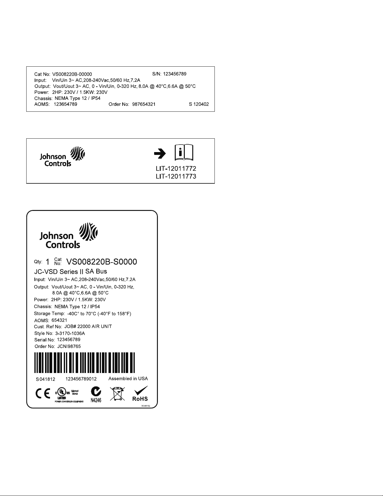
Make sure that the part number indicated on the nameplate
corresponds with the catalog number on your order.
If shipping damage has occurred, please contact and file a
claim with the carrier involved immediately.
Note: Do not destroy the packing. The template printed on
the protective cardboard can be used for marking the
mounting points of the VSD Series II VSD on the wall
or in a cabinet.
VSD Series II LIT12011771—April 2013 www.johnsoncontrols.com 1
VSD Series II Overview
Rating Plates
Manuals
Carton Label
2 VSD Series II LIT12011771—April 2013 www.johnsoncontrols.com
Catalog Number Selection
VS 3D4 4 1 1 B -S 0000
Base Product
VS = VSD Series
310
Voltage
1 = 208V
2 = 230V
4 = 480V
5 = 575V
1
Open Style Amps/Rating
208–240 Volts 3PH 380–480 Volts 3PH
3D7 = 3.7 Amp (3/4 Hp, 0.75 kW)
4D8 = 4.8 Amp (1 Hp, 1.1 kW)
6D6 = 6.6 Amp (1.5 Hp, 1.1 kW)
8D0 = 8 Amp (2 Hp, 1.5 kW)
011 = 11 Amp (3 Hp, 2.2 kW)
012 = 12 Amp (4 Hp, 3 kW)
018 = 18 Amp (5 Hp, 4 kW)
024 = 24 Amp (7.5 Hp, 5.5 kW)
031 = 31 Amp (10 Hp, 7.5 kW)
048 = 48 Amp (15 Hp, 11 kW)
062 = 62 Amp (20 Hp, 15 kW)
075 = 75 Amp (25 Hp, 18.5 kW)
088 = 88 Amp (30 Hp, 22 kW)
105 = 105 Amp (40 Hp, 30 kW)
140 = 140 Amp (50 Hp, 37 kW)
170 = 170 Amp (60 Hp, 45 kW)
205 = 205 Amp (75 Hp, 55 kW)
261 = 261 Amp (100 Hp, 75 kW)
310 = 310 Amp (125 Hp, 90 kW)
3D4 = 3.4 Amp (1.5 Hp, 1.1 kW)
4D8 = 4.8 Amp (2 Hp, 1.5 kW)
5D6 = 5.6 Amp (3 Hp, 2.2 kW)
8D0 = 8 Amp (4 Hp, 3 kW)
9D6 = 9.6 Amp (5 Hp, 4 kW)
012 = 12 Amp (7.5 Hp, 5.5 kW)
016 = 16 Amp (10 Hp, 7.5 kW)
023 = 23 Amp (15 Hp, 11 kW)
031 = 31 Amp (20 Hp, 15 kW)
038 = 38 Amp (25 Hp, 18.5 kW)
046 = 46 Amp (30 Hp, 22 kW)
061 = 61 Amp (40 Hp, 30 kW)
072 = 72 Amp (50 Hp, 37 kW)
087 = 87 Amp (60 Hp, 45 kW)
105 = 105 Amp (75 Hp, 55 kW)
140 = 140 Amp (100 Hp, 75 kW)
170 = 170 Amp (125 Hp, 90 kW)
205 = 205 Amp (150 Hp, 110 kW)
261 = 261 Amp (200 Hp, 132 kW)
310 = 310 Amp (250 Hp, 160 kW)
Options (Ordered Separately)
VS-XMX-K9-FS4-5 = Aux Contacts
Qty 2 (FS4-5 Bypass and Drive Output Contactors)
VS-XMX-K9-FS6-9 = Aux Contacts
Qty 2 (FS6-9 Bypass and Drive Output Contactors)
Extended I/O Options in Slot D and E
(Ordered Separately)
VS-XMX-B1 = 6 DI or DO, 1 ext +24 Vdc/EXT +24 Vdc
Programmable
VS-XMX-B2 = 1 RO (NC/NO), 1 RO (NO), 1 Thermistor
VS-XMX-B4 = 1 AI (mA isolated), 2 AO (mA isolated)
VS-XMX-B5 = Card-3 Relay Dry Contact
VS-XMX-B9 = 1 RO (NO), 5 DI 42–240 Vac Input
VS-XMX-BF = Expander IO—1*AO, 1*DO, 1*RO
VS-XMX-CS = SA Bus (JC-VSD only)
VS-XMX-C4 = Lon Works Comm Card
I/O Options in Slot B
(Ordered Separately)
VS-XMX-F1 = 3 relay (spare/replacement part only—
not option w/standard VSD)
VS-XMX-F2 = 2 relay and 1 Thermistor—not available
with L3/L4 Pilot light option replaces standard
Relay1 pcb in Slot B and Fault Relay function
Enclosure Rating
1 = Nema-UL Type 1 (IP21)
2 = Nema-UL Type 12 (IP54)
4 = Flange Mtd for FS8 and
FS9 (IP00)
Drive Style
0 = Open
RS-485 Optional Comms Slot D and E
0 = STD BACnet/Modbus
S = SA Bus, CS card (added to JC-VSD)
L = Lon Works, C4 Card (Open Only)
1
Revision
B = Rev 2 (Americas)
D = Rev 2 (Canada)
1
VSD Series II Open Drives
VSD Series II Overview
Note
1
Solutions pending. Check with your Johnson Controls representative for availability.
VSD Series II LIT12011771—April 2013 www.johnsoncontrols.com 3

VSD Series II Overview
Power Ratings and Product Selection
VSD Series II Drives—208–230 Volt
NEMA Type 1/IP21 or NEMA Type 12/IP54
Drive Rated Current and hp
De-Rated
Drive Rating
FS
Frame
Size
Low Overload
Full Load
Amps at 40°C
230V
60 Hz
Horsepower
Drive
Input
Amps
NEC Motor
60 Hz
230V Amps
1
Low Overload
Full Load
Amps at 50°C
FS4 3.7 0.75 3.2 3.2 2.6 0.55 VS3D72x0B-00000
4.8 1 4.3 4.2 3.7 0.75 VS4D82x0B-00000
6.6 1.5 6 6 4.6 1.1 VS6D62x0B-00000
8 2 7.2 6.8 6.6 1.5 VS8D02x0B-00000
11 3 9.7 9.6 8 2.2 VS0112x0B-00000
12.5 4 10.9 N/A 9 3 VS0122x0B-00000
FS5 18 5 16.1 15.2 12.5 4 VS0182x0B-00000
24 7.5 21.7 22 18 5.5 VS0242x0B-00000
31 10 27.7 28 25 7.5 VS0312x0B-00000
FS6 48 15 43.8 42 31 11 VS0482x0B-00000
62 20 57 54 48 15 VS0622x0B-00000
FS7 75 25 69 68 62 18.5 VS0752x0B-00000
88 30 82.1 80 75 22 VS0882x0B-00000
105 40 99 104 88 30 VS1052x0B-00000
FS8 140 50 133 130 114 37 VS1402x0B-00000
170 60 163 154 140 45 VS1702x0B-00000
205 75 198 192 170 55 VS2052x0B-00000
FS9 261 100 256 248 211 75 VS2612x0B-00000
310 125 303 N/A 251 90 VS3102x0B-00000
Notes
1
For sizing reference, full-load motor running currents—UL508C.
2
If SA-Bus is required, replace -00000 with -S0000.
Assigned
Motor Ratings x = Can Be:
Open Drive
kW
1 = N1 = IP21
2 = N12 = IP54
230V
50 Hz
Catalog Number
2
4 VSD Series II LIT12011771—April 2013 www.johnsoncontrols.com

VSD Series II Overview
VSD Series II Drives—380–480 Volt
NEMA Type 1/IP21 or NEMA Type 12/IP54
Assigned
Motor Ratings x = Can Be:
Open Drive
kW
1 = N1 = IP21
2 = N12 = IP54
400V
50 Hz
Catalog Number
1
De-Rated
Low Overload
Full Load
Amps at 50°C
FS
Frame
Size
Drive Input Rated Current and hp
Low Overload
Full Load
Amps at 40°C
460V
60 Hz
Horsepower
Drive
Input
Amps
NEC Motor
60 Hz
460V Amps
FS4 3.4 1.5 3.4 3 2.6 1.1 VS3D44x0B-00000
4.8 2 4.6 3.4 3.4 1.5 VS4D84x0B-00000
5.6 3 5.4 4.8 4.3 2.2 VS5D64x0B-00000
8.0 5 8.1 7.6 5.6 3.0 VS8D04x0B-00000
9.6 5 9.3 N/A 8 4 VS9064x0B-00000
12 7.5 11.3 11 9.6 5.5 VS0124x0B-00000
FS5 16 10 15.4 14 12 7.5 VS0164x0B-00000
23 15 21.3 21 16 11 VS0234x0B-00000
31 20 28.4 27 23 15 VS0314x0B-00000
FS6 38 25 36.7 34 31 18.5 VS0384x0B-00000
46 30 43.6 40 38 22 VS0464x0B-00000
61 40 58.2 52 46 30 VS0614x0B-00000
FS7 72 50 67.5 65 61 37 VS0724x0B-00000
87 60 85.3 77 72 45 VS0874x0B-00000
105 75 100.6 96 87 55 VS1054x0B-00000
FS8 140 100 139.4 124 105 75 VS1404x0B-00000
170 125 166.5 156 140 90 VS1704x0B-00000
205 150 200 180 170 110 VS2054x0B-00000
FS9 261 200 258 240 205 132 VS2614x0B-00000
310 250 303 302 251 160 VS3104x0B-00000
2
VSD Series II Variable Speed Drive Option Boards
Assigned to
Option Board
Part Number
Control
Module Slot: Description
VS-XMX-B1 D or E Expanded 6 digital output—two outputs are programmable as digital inputs or outputs
VS-XMX-B2 D or E Expanded relay outputs—two programmable relays (each with a NO and NC contact) and thermistor input
VS-XMX-B4 D or E Expanded analog inputs and outputs—one analog input and two analog outputs (isolated)
VS-XMX-B5 D or E Expanded relay outputs—contains three programmable relays (one NO contact each)
VS-XMX-B9 D or E Accepts up to five AC inputs (42–240 Vac) and one relay output (NO)
VS-XMX-BF D or E Expanded analog and digital output—one analog, one digital, and one relay output (NO)
®
VS-XMX-C4 D or E LonWorks
communication
VS-XMX-CS D or E SA-Bus communication
Notes
1
For sizing reference, full-load motor running currents—UL508C.
2
If SA-Bus is required, replace -00000 with -S0000.
VSD Series II LIT12011771—April 2013 www.johnsoncontrols.com 5

HVAC Application
HVAC Application
The Johnson Controls VSD Series II drive contains a
preloaded application for instant use.
The parameters of this application are listed in the complete
Application Manual. The Application Manual can be found at
http://www.johnsoncontrols.com —> HVAC Controls —>
Variable Speed Drives.
Specific Functions of Johnson Controls
VSD Series II Application
The Johnson Controls VSD Series II application is an
easy-to-use application for not only basic pump and fan
applications where only one motor and one drive is needed,
but also offers extensive possibilities for PID control.
Features
●
Startup Wizard for extremely fast setup for basic pump or
fan applications
●
Mini-Wizards to ease the setup of applications
●
Hand/Off/Auto button for easy change between Hand
(keypad), OFF, and Auto (Remote control) place. The auto
control place is selectable by parameter (I/O or Fieldbus)
●
Control page for easy operation and monitoring of the
most essential values
●
Run interlock input (damper interlock). Drive will not start
before this input is activated
●
Maximum output frequency 320 Hz
●
Real-time clock and timer functions available. Possible to
program three time channels to achieve different functions
on the drive (for example, Start/Stop and Preset
frequencies)
●
External PID-controller available. Can be used to control a
valve using the drive’s I/O, for example
●
Sleep mode function which automatically enables and
disables drive running with user defined levels to save
energy
●
Two-zone PID-controller (two different feedback signals;
minimum and maximum control)
●
Two setpoint sources for the PID-control. Selectable with
digital input
●
PID setpoint boost function
●
Feed forward function to improve the response to the
process changes
●
Process value supervision
●
Multi-pump control
●
Pressure loss compensation for compensating pressure
losses in the pipework, for example, when sensor is
incorrectly placed near the pump or fan
6 VSD Series II LIT12011771—April 2013 www.johnsoncontrols.com
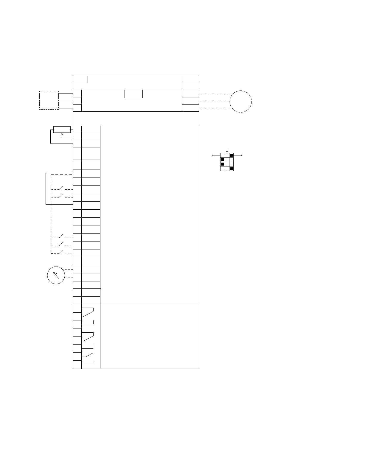
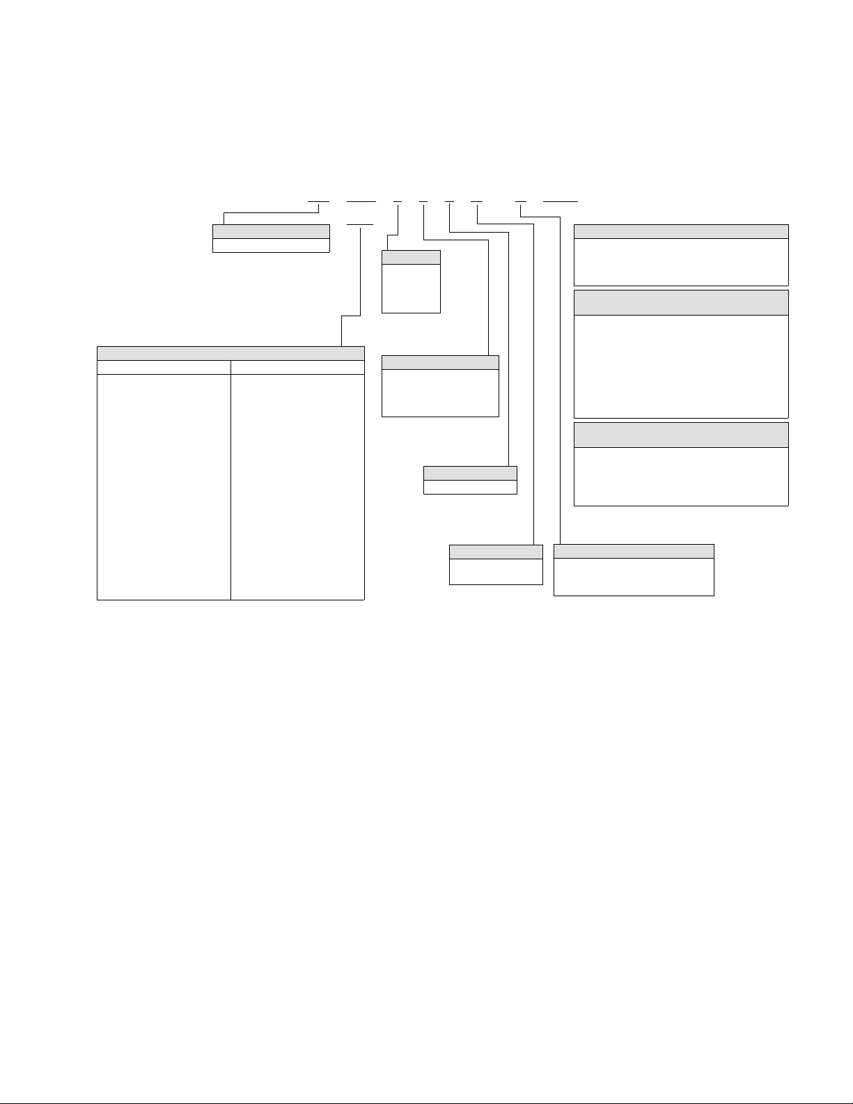
Example of Control Connections
Slot A
1
2
3
4
5
6
7
8
9
10
11
12
13
14
15
16
17
18
19
A
+10V
AI–1+
V
in
AI–2+
AI–2–
24V
out
GND
DIN1
DIN2
DIN3
24V
out
GND
DIN4
DIN5
DIN6
AO–1+
AO–1–
DATA–
Reference Output
Analog Input Voltage (Range 0–10 Vdc)
(can be programmed to current 4–20 mA)
Analog Output Common (Ground)
Analog Input Common
PI Setpoint or Feedback
Control Voltage Output (0.1A max.)
I/O Ground
START/STOP (Contact closed = start)
External Fault (Closed = fault)
Run Interlock Permissive IP Interlock
(Closed = OK)
DIN1–DIN6 Common
Control Voltage Output (0.1A max.)
I/O Ground
Fire Mode (Contact closed = fire mode)
Force Bypass (Contact closed = bypass)
DIN1–DIN6 Common
Output Frequency (0–20 mA)
Analog Output Common (Ground)
RS-485 DATA–
Speed Select 0–100% (Preset speed)
U (T1)
V (T2)
W (T3)
R+
R–
L1
L2
L3
Three-Phase Input
Input
(Single-Phase not available)
Three-Phase
Output
DB
Chopper
Terminal
Factory Default Signal
Resistor
Analog Input Current (Range 4–20 mA)
(can be programmed to voltage 0–10 Vdc)
PI Setpoint or Feedback
B
DATA+
RO1 Bypass Run
RO2 Drive Run
RO3 Fault
24 Vdc/8A
250 Vac/8A
125 Vdc/0.4A
Relay Board 1
Default Signal
21
22
23
24
25
26
32
33
Slot B
Analog
RS-485 DATA+
Factory
Jumper
COM
CMB
30
24 VdcinAuxiliary Input Voltage
Circuit
Breaker
Optional
Motor
RJ-45
BACnet/IP Ethernet Industrial Protocol
Modbus/TCP Transmission Control Protocol (Ethernet Based)
5% DC Link
Reactor
Programmable BACnet,
Modbus, FLN, N2
ON
CURRENT
CURRENT
CURRENT
RS485
AO1
AI2
AI1
OFF
VOLTAGE
VOLTAGE
VOLTAGE
Test
Control Connections
HVAC Application
VSD Series II LIT12011771—April 2013 www.johnsoncontrols.com 7
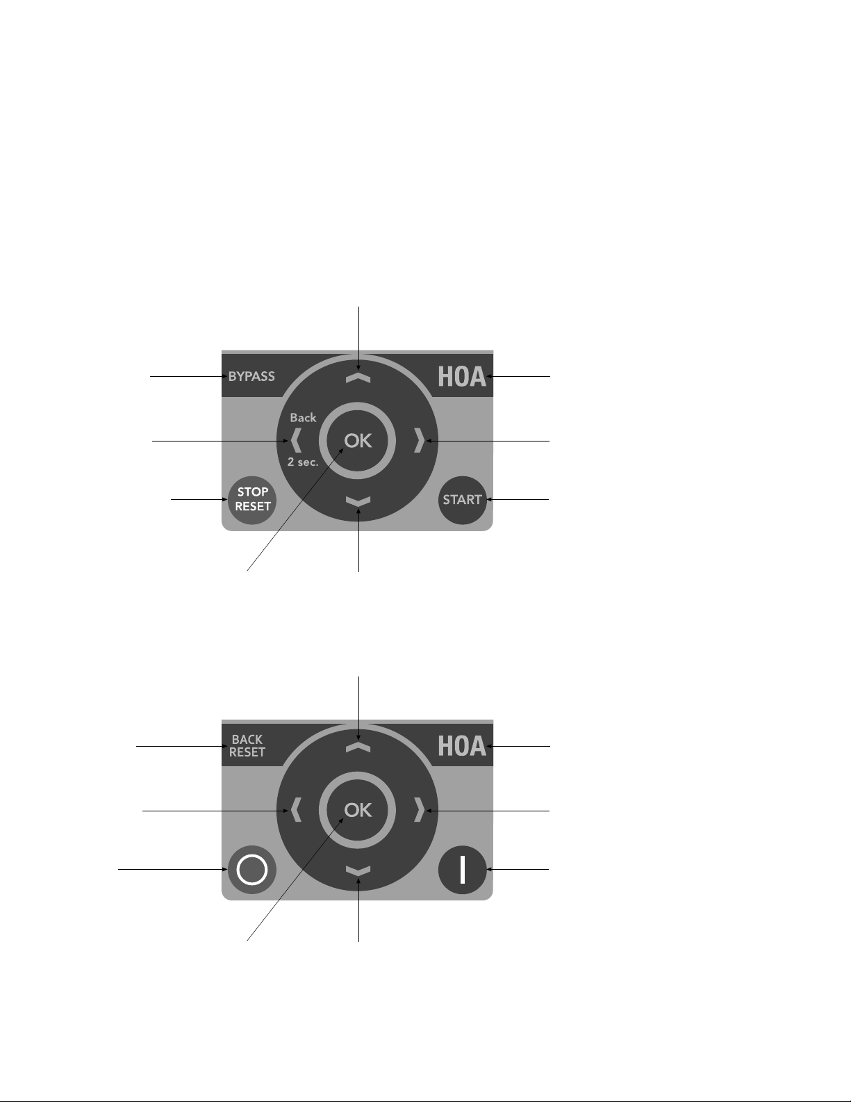
Keypad of the Drive
Switching Between
Drive and Bypass
Move Cursor Left
Back when Pressed
for two Seconds
Stop Button/Fault Reset Start Button
Change Control Place
Between Hand-Off-Auto
Move Cursor Right
Increase Value
Scroll Menu Up
Decrease Value
Scroll Menu Down
Enter Menu
Confirm Selection
Back Fault Reset
Move Cursor Left
Stop Button Start Button
Change Control Place
Between Hand-Off-Auto
Move Cursor Right
Increase Value
Scroll Menu Up
Decrease Value
Scroll Menu Down
Enter Menu
Confirm Selection
Keypad of the Drive
The control keypad is the interface between the Johnson
Controls VSD Series II frequency converter and the user.
With the control keypad it is possible to control the speed of
a motor, to supervise the state of the equipment and to set
the frequency converter’s parameters.
US Keypad Buttons
There are two different keypads used with the VSD Series II
drive. The North American Keypad is slightly different than
the EMEA Keypad. Functionality is quite similar. The EMEA
keypad does not support the bypass functionality commonly
used in the United States.
EMEA Keypad Buttons
8 VSD Series II LIT12011771—April 2013 www.johnsoncontrols.com
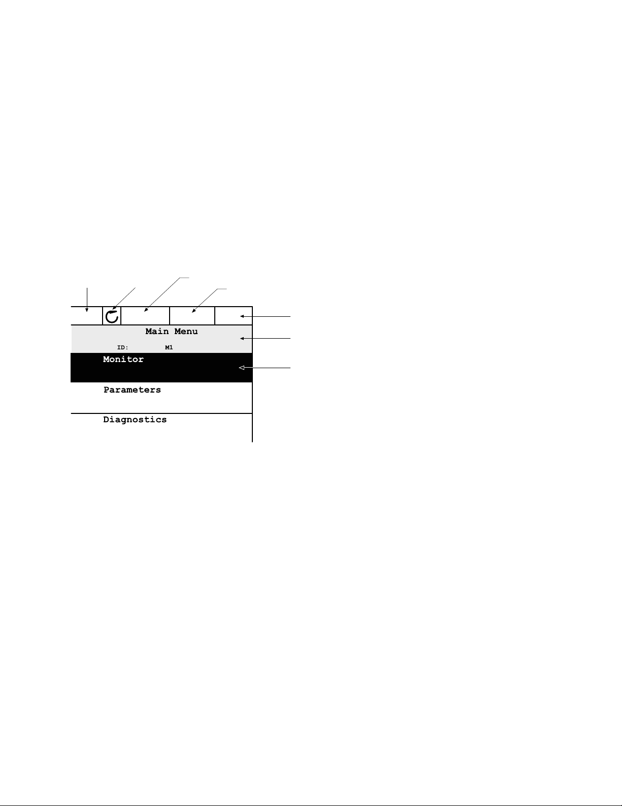
Keypad Display
Status Field
STOP/RUN
STOP
E-Energy Hand I/O
Direction
Run Mode
Hand/Off/Auto
Control Place
PC/IO/KEYPAD/FIELDBUS
Location Field
(Parameter ID number and
current menu location)
Activated Group/Item
Press OK to Enter
The keypad display indicates the status of the motor and the drive and any irregularities in
motor or drive functions. On the display, the user sees information about his present location
in the menu structure and the item displayed.
Main Menu
The data on the control keypad are arranged in menus and submenus. Use the up and down
arrows to move between the menus. Enter the group/item by pressing the OK button and
return to the former level by pressing the Back/Reset button.
The Location field indicates your current location. The Status field gives information about the
present status of the drive. See “Control Connections” on Page 7.
Main Menu
Keypad of the Drive
Using the Graphical Keypad
Editing Values
Change value of a parameter following the procedure below:
1. Locate the parameter.
2. Enter the Edit mode.
3. Set new value with the up/down arrow buttons. You can also move from digit to digit with
the arrow buttons left/right if the value is numerical and then change the value with the
up/down arrow buttons.
4. Confirm change with OK button or ignore change by returning to previous level with Back/
Reset button.
VSD Series II LIT12011771—April 2013 www.johnsoncontrols.com 9
Keypad of the Drive
STOP READY I/O
STOP READY I/O
OK OK
OK
STOP READY I/O
OR:
BACK
RESET
Editing Values on Graphical Keypad
STOP READY I/O
HOA Control Button
The HOA (Hand-Off-Auto) button is used for two functions:
to quickly access the Control page and to easily change
between the Hand (Keypad), Off, and Auto (Remote) control
places.
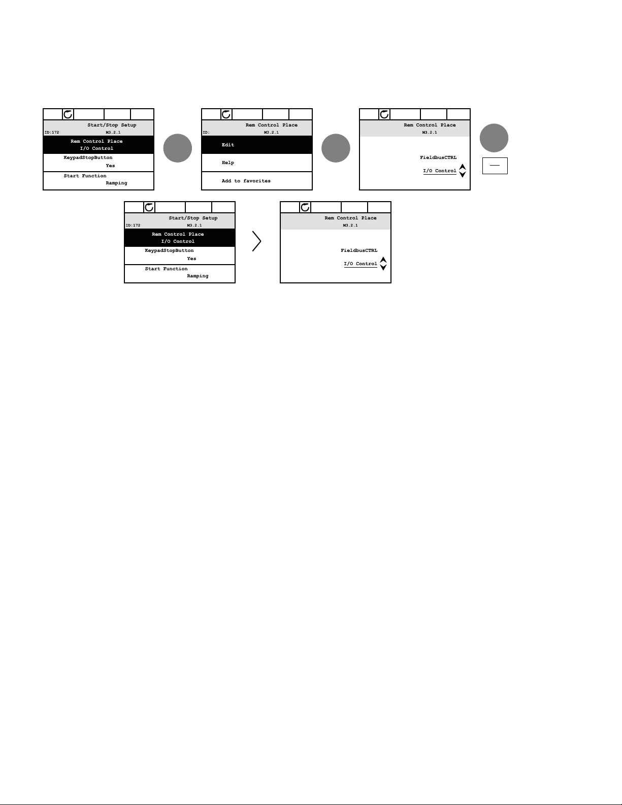
Control Place
The control place is the source of control where the drive can
be started and stopped. Every control place has its own
parameter for selecting the frequency reference source. In
the HVAC drive, the Hand control place is always the keypad.
The Auto control place is determined by parameter P2.1.1
(Keypad, I/O Terminal, I/O three-wire, or Fieldbus CTRL). The
selected control place can be seen on the status bar of the
keypad.
Local Control
The keypad is always used as control place while in hand
control. Hand control has higher priority than auto control.
Therefore, if, for example, bypassed by parameter P2.1.17
through digital input while in Remote, the control place will
still switch to Keypad if Hand is selected. Switching between
Hand, Off, and Auto Control can be done by pressing the
HOA button on the keypad.
STOP READY I/O
Changing Control Place
Change of control place from Hand to Auto (keypad).
1. Anywhere in the menu structure, push the HOA button.
2. Push the arrow up or the arrow down button to select
Hand/Off/Auto and confirm with the OK button.
3. On the next display, select Hand, Off, or Auto and again
confirm with the OK button.
4. The display will return to the same location as it was
when the HOA button was pushed. However, if the
Remote control place was changed to Hand (Keypad)
you will be prompted for keypad reference.
10 VSD Series II LIT12011771—April 2013 www.johnsoncontrols.com
Accessing the Control Page
HOA
STOP READY Keypad
OK
OK
STOP READY Keypad
OK
STOP READY I/O
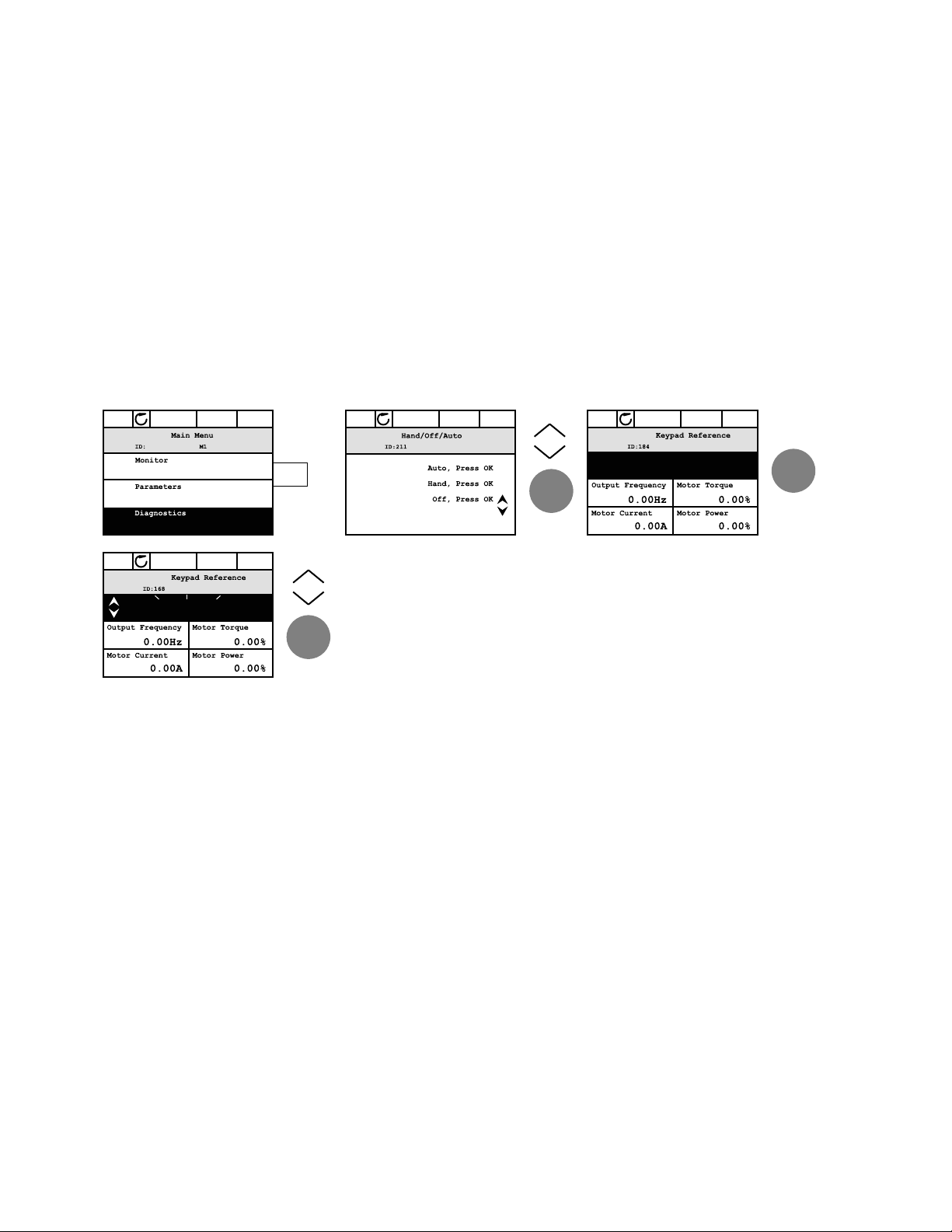
The Control page is meant for easy operation and monitoring of the most essential values.
1. Anywhere in the menu structure, push the HOA button.
2. Push the arrow up or the arrow down button to select Control page and confirm with the
OK button.
3. The control page appears. If keypad control place and keypad reference are selected to
be used, you can set the Keypad reference after having pressed the OK button. If other
control places or reference values are used, the display will show Frequency reference
which is not editable. The other values on the page are Multimonitoring values. You can
choose which values appear here for monitoring (for this procedure, see Application
Manual).
Accessing Control Page
Keypad of the Drive
STOP READY Keypad
0.00 Hz
Edit
0.00 Hz
VSD Series II LIT12011771—April 2013 www.johnsoncontrols.com 11
Keypad of the Drive
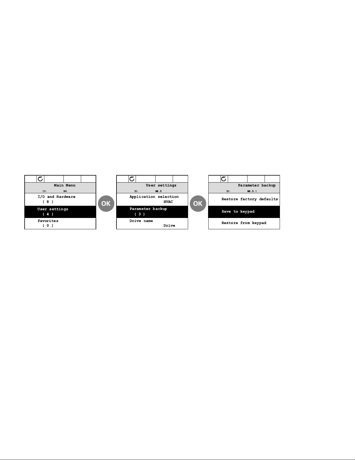
Copying Parameters
The parameter copy function can be used to copy parameters from one drive to another.
The parameters are first saved to the keypad, then the keypad is detached and connected to
another drive. Finally, the parameters are downloaded to the new drive, restoring them from
the keypad.
Before any parameters can successfully be copied from one drive to another, the drive has to
be stopped when the parameters are downloaded.
●
First, go into User settings menu and locate the Parameter backup submenu. In the
Parameter backup submenu, there are three possible functions to be selected:
1. Restore factory defaults will re-establish the parameter settings originally made at the
factory.
2. By selecting Save to keypad you can copy all parameters to the keypad.
3. Restore from keypad will copy all parameters from keypad to a drive.
Parameter Copy
STOP READY Keypad
STOP READY Keypad STOP READY Keypad
Note: If the keypad is changed between drives of different sizes, the copied values of these
parameters will not be used:
Motor nominal current (P2.1.12)
Motor nominal voltage (P2.1.13)
Motor nominal speed (P2.1.15)
Motor power factor (P2.1.16)
Motor nominal frequency (P2.1.14)
Service factor (P2.1.18)
Switching frequency (P2.7.7)
Motor current limit (P2.1.17)
Maximum frequency (P2.1.9)
12 VSD Series II LIT12011771—April 2013 www.johnsoncontrols.com
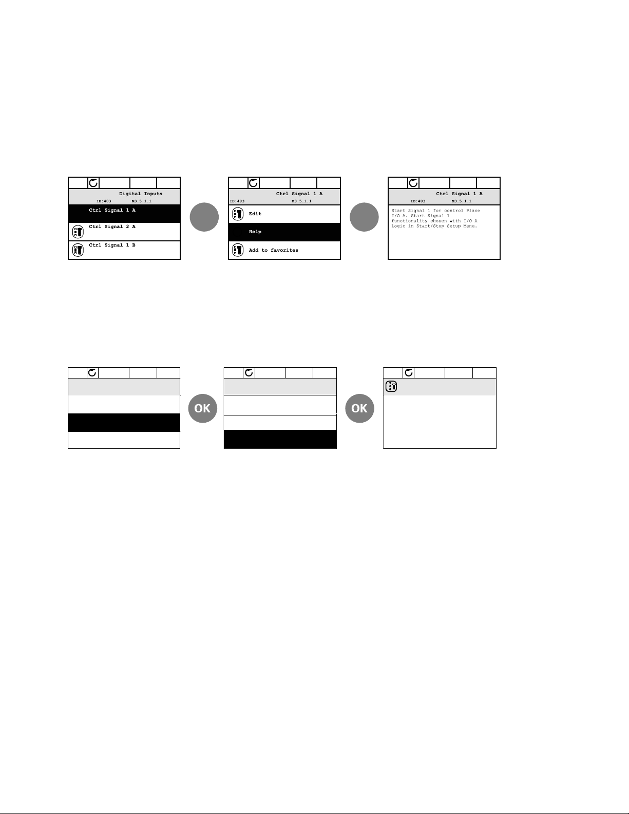
Help Texts
STOP READY I/O STOP READY I/O
OK OK
STOP READY I/O
Basic Sett ings
Motor Nom Voltg
230.00 V
Motor Nom Speed
1430 rpm
The graphical keypad features instant help and information displays for various items.
All parameters offer an instant help display. Select Help and press the OK button.
Text information is also available for faults, alarms, and the Startup Wizard.
Help Text Example
Adding Item To Favorites
You might need to refer to certain parameter values or other items often. Instead of locating
them one by one in the menu structure, you may want to add them to a folder called Favorites
where they can easily be reached.
Keypad of the Drive
Adding Item To Favorites
STOP READY I/O STOP READY I/O STOP READY I/O
Motor Nom Freq
50.00 Hz
Motor N om Freq
Edit
Help
Add to favorites
Motor N om Fr eq
was added to
favorites. Press OK
to continue.
VSD Series II LIT12011771—April 2013 www.johnsoncontrols.com 13
Keypad of the Drive
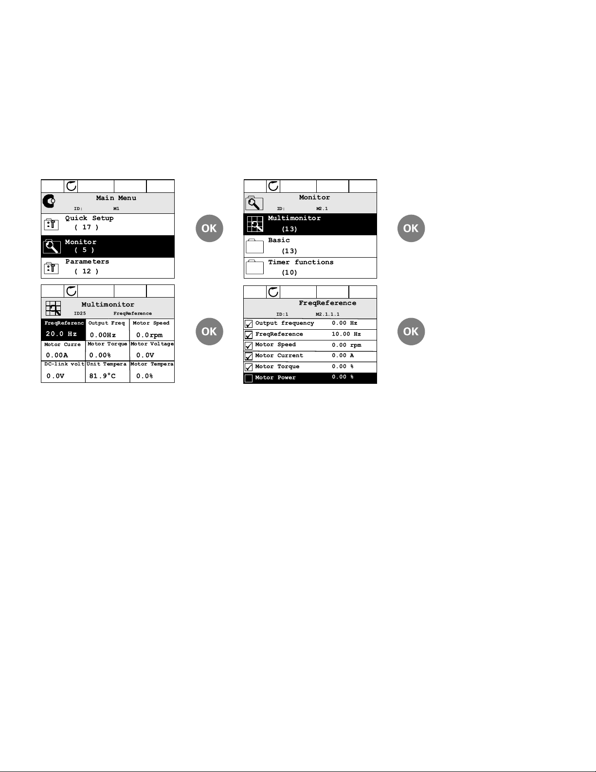
Monitor
Multi-Monitor
On the multi-monitor page, you can collect nine values that you wish to monitor.
Multi-Monitoring Page
STOP READY I/O STOP READY I/O
STOP READY I/O STOP READY I/O
Change the monitored value by activating the value cell (with arrow buttons left/right) and
clicking OK. Then choose a new item on the Monitoring values list and click OK again.
14 VSD Series II LIT12011771—April 2013 www.johnsoncontrols.com

VSD Series II—Startup
BACK
RESET
Startup Wizard
In the Startup Wizard, you will be prompted for essential
information needed by the drive so that it can start
controlling your process. In the Wizard, you will need the
following keypad buttons:
Left/Right arrows. Use these to easily move
between digits and decimals.
Up/Down arrows. Use these to move between
options in menu and to change value.
OK
Once you have connected power to your Johnson Controls
VSD Series II frequency converter, follow these instructions
to easily set up your drive.
1
2
3
4
5
6
Note
1
OK button. Confirm selection with this button.
Back/Reset button. Pressing this button, you can
return to the previous question in the Wizard. If
pressed at the first question, the Startup Wizard will
be cancelled.
Run Startup Wizard Yes
Language Select Depends on language package
Daylight Saving
1
Time
1
Day
1
Year
These questions appear if battery is installed.
1
No
Russia
US
EU
OFF
hh:mm:ss
dd.mm.
yyyy
VSD Series II—Startup
7
8
9
10
11
12
13
14
15
16
17
18
19
20
Now the Startup Wizard is done.
The Startup Wizard can be re-initiated by pressing and
holding the back/reset button for two seconds. The Startup
Wizard will appear upon next power up.
Application VSD Series II Standard
PID
Multi-Pump
Bypass Enabled
Disabled
Motor Nominal Current Min: 0.26A
Max: Drive Dependent
Motor Nominal Voltage Min: 180.0V
Max: 690.0V
Motor Nominal Frequency Min: 8 Hz
Max: 320 Hz
Motor Nominal Speed Min: 24 RPM
Max: 19200 RPM
Min Frequency Min: 0 Hz
Max: 60 Hz
Max Frequency Min: 12 Hz
Max: 320 Hz
Accel Time 1 Min: 0.1s
Max: 3000s
Decel Time 1 Min: 0.1s
Max: 3000s
StartSourceHand Keypad
FieldbusCTRL
I/O Three-Wire
I/O Terminal
StartSourceAuto I/O Terminal
Keypad
FieldbusCTRL
I/O Three-Wire
SpeedSetptHand Keypad Ref
P1D1 Activated
AI1 + AI2
AI2
AI1
Fieldbus
SpeedSetptAuto PID1 Activated
AI1 + AI2
AI2
AI1
Fieldbus
Keypad Ref
VSD Series II LIT12011771—April 2013 www.johnsoncontrols.com 15

VSD Series II—Startup
PID Mini-Wizard
The PID Mini-Wizard is activated in the Quick Setup menu.
This Wizard presupposes that you are going to use the PID
controller in the “one feedback/one setpoint” mode. The
control place will be I/O A and the default process unit “%”.
The PID Mini-Wizard asks for the following values to be set:
1
2
3
FeedBack1 Srce AI2
AI1
Not Used
ProceDataIn8
ProceDataIn7
ProceDataIn6
ProceDataIn5
ProceDataIn4
ProceDataIn3
ProceDataIn2
ProceDataIn1
AI6
AI5
AI4
AI3
Process Unit Selection (Several Selections)
Process Unit Min —
Multi-Pump
If Multi-Pump is the selected application, parameter group
2.16 will be visible in the menu structure. Default values may
need to be adjusted to meet your application needs.
Parameter
Group Name
Parameter Group 2.16:
Multi-Pump
Parameter
Number
P2.16.1 Number of motors
P2.16.2 Interlock function
P2.16.3 Include FC
P2.16.4 Autochange
P2.16.5 Autochange interval
P2.16.6 Autochange frequency limit
P2.16.7 Autochange motor limit
P2.16.8 Bandwidth
P2.16.9 Bandwidth delay
Parameter
Name
4
5
6
7
Process Unit Max —
P-Gain Min: 0%
Max: 200%
Integration Time Min: 0.00s
Max: 600.00s
SetPT1 Source Keypad SP1
Not Used
ProceDataIn8
ProceDataIn7
ProceDataIn6
ProceDataIn5
ProceDataIn4
ProceDataIn3
ProceDataIn2
ProceDataIn1
AI6
AI5
AI4
AI3
AI2
AI1
16 VSD Series II LIT12011771—April 2013 www.johnsoncontrols.com

Menu Structure
Keypad Menus
Monitor Basic Diagnostics Active Faults
Timer Functions Reset Faults
Multimonitor Fault History
Parameters Basic Parameters Total Counters
Analog Inputs Trip Counters
Digital Inputs Software Info
Analog Outputs I/O & Hardware Basic I/O
Digital Outputs Slot D
Drive Control Slot E
Motor Control Real Time Clock
Protections Power Unit Settings
Fixed Frequencies Keypad
Fire Mode RS485
Multi-Pump —
Braking Ethernet
Fieldbus User Settings —
Second Parameter Set Favorites —
Timer Functions
Menu St ructure
VSD Series II LIT12011771—April 2013 www.johnsoncontrols.com 17

Parameter Functions
Parameter Functions
Basic Monitoring Functions
Parameter
Number Parameter Name Unit ID Description
V1.1.1 Output frequency Hz 1 Output Frequency of the Drive
V1.1.2 Frequency Reference Hz 25 Frequency Reference to Motor Control
V1.1.3 Motor Speed RPM rpm 2 Motor speed in rpm
V1.1.4 Motor Current A 3 Motor Current
V1.1.5 Motor Torque % 4 Calculated Shaft Torque
V1.1.6 Motor Power % % 5 Total Power Consumption of AC Drive
V1.1.7 Motor Voltage V 6 Motor Voltage
V1.1.8 DC-Link Voltage V 7 DC-Link Voltage
V1.1.9 Unit Temperature °C 8 Heatsink temperature
V1.1.10 Motor Temperature % 9 Calculated Motor Temperature
V1.1.11 Analog Input 1 % 13 Analog input signal scaled according to the range or custom min and max chosen
V1.1.12 Analog Input 2 % 14 Analog input signal scaled according to the range or custom min and max chosen
V1.1.13 Analog Output 1 % 26 Value of analog output in % of the signal range
V1.1.14 DI1, DI2, DI3 Binary 15 This monitor value shows the status of the I/Os
V1.1.15 DI4, DI5, DI6 Binary 16 This monitor value shows the status of the I/Os
V1.1.16 PID1 Setpoint % 20 Setpoint value fed to the PID controller in process units
V1.1.17 PID1 Feedback % 21 Feedback Value fed to the PID controller in process units
V1.1.18 PID1 Error % 22 Error value of the PID controller. Deviation of the feedback from setpoint in process units.
V1.1.19 PID2 Setpoint % 83 Setpoint value fed to the PID controller in process units
V1.1.20 PID2 Feedback % 84 Feedback Value fed to the PID controller in process units
V1.1.21 PID2 Error % 85 Error value of the PID controller. Deviation of the feedback from setpoint in process units.
V1.1.22 Drive Status Word BitCoded 43 Bitcoded status of the drive. B1=Ready, B2=Run, B3=Fault, B6=RunEnable, B7=Alarm Active,
V1.1.23 Motor Speed % % 1360 Percent of full motor speed
V1.1.24 Last Active Fault Num 37 The fault code of the latest activated fault that has not been reset
in the I/O config menu
in the I/O config menu
B12=Run Request, B13=Motor Regulator Active
18 VSD Series II LIT12011771—April 2013 www.johnsoncontrols.com

Parameter Functions
Timer Monitoring Functions
Parameter
Number Parameter Name Unit ID Description
V1.2.1 TC1, TC2, TC3 ON/OFF 1703 This monitor value shows the status of the time channels
V1.2.2 Interval 1 ON/OFF 1704 This monitor value shows the status of the timer interval
V1.2.3 Interval 2 ON/OFF 1705 This monitor value shows the status of the timer interval
V1.2.4 Interval 3 ON/OFF 1706 This monitor value shows the status of the timer interval
V1.2.5 Interval 4 ON/OFF 1707 This monitor value shows the status of the timer interval
V1.2.6 Interval 5 ON/OFF 1708 This monitor value shows the status of the timer interval
V1.2.7 Timer 1 sec 1709 If the timer has been activated, this monitor value shows the remaining time of the timer.
V1.2.8 Timer 2 sec 1710 If the timer has been activated, this monitor value shows the remaining time of the timer.
V1.2.9 Timer 3 sec 1711 If the timer has been activated, this monitor value shows the remaining time of the timer.
V1.2.10 Real Time Clock h/m/s 1712 Time of Day (Military Time)
Multi-Monitor Functions
Parameter
Number Parameter Name Unit ID Description
V1.3.x.1 Drive Status Word Binary 43 Bitcoded status of the drive. B1=Ready, B2=Run, B3=Fault, B6=RunEnable, B7=Alarm Active,
V1.3.x.2 Analog Input 1 % 13 Analog input signal scaled according to the range or custom min and max chosen
V1.3.x.3 Analog Input 2 % 14 Analog input signal scaled according to the range or custom min and max chosen
V1.3.x.4 Analog Output 1 % 26 Value of analog output in % of the signal range
V1.3.x.5 AutoChange N/A 1720 No Function
V1.3.x.6 DC-Link Voltage V 7 DC-Link Voltage of the Drive
V1.3.x.7 DI1, DI2, DI3 Binary 15 This monitor value shows the status of the I/Os
V1.3.x.8 DI4, DI5, DI6 Binary 16 This monitor value shows the status of the I/Os
V1.3.x.9 RO1, RO2, RO3 Binary 17 This monitor value shows the status of the I/Os
V1.3.x.10 Frequency Reference Hz 25 Frequency Reference to Motor Control
V1.3.x.11 Interval 1 ON/OFF 1704 This monitor value shows the status of the timer interval
V1.3.x.12 Interval 2 ON/OFF 1705 This monitor value shows the status of the timer interval
V1.3.x.13 Interval 3 ON/OFF 1706 This monitor value shows the status of the timer interval
V1.3.x.14 Interval 4 ON/OFF 1707 This monitor value shows the status of the timer interval
V1.3.x.15 Interval 5 ON/OFF 1708 This monitor value shows the status of the timer interval
V1.3.x.16 Motor Current A 3 Motor Current
V1.3.x.17 Motor Power KW KW 73 Calculated Power Consumption of the Motor
V1.3.x.18 Motor Power % % 5 Total Power Consumption of AC Drive
V1.3.x.19 Motor Speed RPM rpm 2 Motor speed in rpm
V1.3.x.20 Motor Torque % 4 Calculated Shaft Torque
V1.3.x.21 Motor Voltage V 6 Motor Voltage
B12=Run Request, B13=Motor Regulator Active
in the I/O config menu
in the I/O config menu
Note: The “x” in the parameter number represents the assembled monitoring window. Values range from 1 to 9.
VSD Series II LIT12011771—April 2013 www.johnsoncontrols.com 19

Parameter Functions
Multi-Monitor Functions, continued
Parameter
Number Parameter Name Unit ID Description
V1.3.x.22 Motor Running Binary 30 This monitor value shows if the motor is running
V1.3.x.23 Motor Temperature % 9 Calculated Motor Temperature
V1.3.x.25 PID1 Status Words 24 This monitor value shows if the PID is Active
V1.3.x.26 PID2 Status Words 87 This monitor value shows if the PID is Active
V1.3.x.27 PID1 Error % 22 Error value of the PID controller. Deviation of the feedback from setpoint in process units.
V1.3.x.28 PID1 Feedback % 21 Feedback Value fed to the PID controller in process units
V1.3.x.29 PID1 Output % 23 Output value delivered from the PID controller in process units
V1.3.x.30 PID1 Setpoint % 20 Setpoint value fed to the PID controller in process units
V1.3.x.31 PID2 Error % 85 Error value of the PID controller. Deviation of the feedback from setpoint in process units.
V1.3.x.32 PID2 Feedback % 84 Feedback Value fed to the PID controller in process units
V1.3.x.33 PID2 Output % 86 Output value delivered from the PID controller in process units
V1.3.x.34 PID2 Setpoint % 83 Setpoint value fed to the PID controller in process units
V1.3.x.35 Real Time Clock h/m/s 1712 Time of Day (Military Time)
V1.3.x.36 Run Request Chain Words 1361 This monitor value shows the status of a run request
V1.3.x.37 TC1, TC2, TC3 ON/OFF 1703 This monitor value shows the status of the time channels
V1.3.x.38 Timer 1 sec 1709 If the timer has been activated, this monitor value shows the remaining time of the timer.
V1.3.x.39 Timer 2 sec 1710 If the timer has been activated, this monitor value shows the remaining time of the timer.
V1.3.x.40 Timer 3 sec 1711 If the timer has been activated, this monitor value shows the remaining time of the timer.
V1.3.x.41 Unit Temperature °C 8 Heatsink temperature
V1.3.x.42 Motor Speed % % 1360 Motor Speed in %
V1.3.x.43 Last Active Fault Num 37 The fault code of the latest activated fault that has not been reset
V1.3.x.44 Run Time Hours Hrs 1364 Drive Run Time in Hours
V1.3.x.45 Power On Hours Hrs 1363 Power On Time in Hours
V1.3.x.46 Frequency Reference Hz 1365 Frequency Reference to Motor Control
V1.3.x.53 Energy Counter varies 2291 Amount of Energy taken from the Supply Network, No Reset
V1.3.x.55 Run Time a d hh:min N/A Run Time of Drive
V1.3.x.56 Power On Time a d hh:min N/A Power On Time of Drive
V1.3.x.57 Start Command Counter Num 2295 The number of times the power unit has been started
V1.3.x.58 Energy Counter varies 2296 Resettable Energy Counter
V1.3.x.60 Run Time N/A N/A N/A
V1.3.x.61 Run Time N/A N/A N/A
V1.3.x.62 Run Time N/A N/A N/A
V1.3.x.63 Power On Time N/A N/A N/A
V1.3.x.64 Power On Time N/A N/A N/A
V1.3.x.65 Power On Time N/A N/A N/A
Note: The “x” in the parameter number represents the assembled monitoring window. Values range from 1 to 9.
20 VSD Series II LIT12011771—April 2013 www.johnsoncontrols.com

Parameters
Basic Parameters
Basic Settings
Parameter
Number Parameter Name
P2.1.1 Application N0202130 = Standard
P2.1.2 ByPass N0112140 = Disabled
P2.1.3 HOA Control Stc N 0 1 0 1359 0 = Keypad Ctrl
P2.1.4 Start Srce Hand N 0 3 0 1300 0 = Keypad
P2.1.5 Speed Setpt Hand N 2 7 2 1301 2 = Keypad Ref
P2.1.6 Start Srce Auto N 0 3 1 1302 0 = Keypad
P2.1.7 Speed Setpt Auto
(see P2.1.5)
P2.1.8 Min Frequency N 0,00 Hz Max frequency 12,00 Hz 101 See Range
P2.1.9 Max Frequency N Min frequency 320,00 Hz 50,00/60,00 102 See Range
P2.1.10 Accel Time 1 Y 0.1 s 3000,0 s 60,0 s 103 See Range
P2.1.11 Decel Time 1 Y 0.1 s 3000,0 s 60,0 s 104 See Range
P2.1.12 Motor Nom Currnt N varies varies varies 113 See Range
P2.1.13 Motor Nom Voltg N 180,0 V 690,0 V varies 110 See Range
P2.1.14 Motor Nom Freq N 12,00 Hz 320,00 Hz 50,00/60,00 111 See Range
P2.1.15 Motor Nom Speed N 24 rpm 19200 rpm 1440/1750 112 See Range
P2.1.16 MotorPowerFactor N 0,30 1,00 0,82 120 See Range
P2.1.17 Current Limit N varies varies varies 107 See Range
P2.1.18 Service Factor N 0,10 2,00 1,00 1357 See Range
Change
in Run Min. Max. Default ID Values
N 2 7 4 1303 2 = Keypad Ref
Parameters
1 =PID
2 = Multi-Pump
1 = Enabled
1 = I/O Terminal
1 = I/O Terminal
2 = I/O 3-wire
3 = FieldbusCTRL
3 = Fieldbus
4 =AI1
5 =AI2
6 =AI1 + AI2
7 = PID1 Activated
1 = I/O Terminal
2 = I/O 3-wire
3 = FieldbusCTRL
3 = Fieldbus
4 =AI1
5 =AI2
6 =AI1 + AI2
7 = PID1 Activated
VSD Series II LIT12011771—April 2013 www.johnsoncontrols.com 21

Parameters
Analog Inputs
Analog Input 1
Parameter
Number Parameter Name
P2.2.1.1 AI1 Signal selection
(Input terminal, TTF)
P2.2.1.2 AI1 Signal Inv Y0103870 = Normal
P2.2.1.3 AI1 Signal Range Y0103790 = 0–10V / 0–20mA
P2.2.1.4 AI1 Custom Min Y –160,00 % 160,00 % 0,00 % 380 See Range
P2.2.1.5 AI1 Custom Max Y –160,00 % 160,00 % 100,00 % 381 See Range
P2.2.1.6 AI1 Filter Time Y 0,00 s 300,00 s 1,00 s 378 See Range
Analog Input 2
Parameter
Number Parameter Name
P2.2.2.1 AI2 Signal selection
(Input terminal, TTF)
P2.2.2.2 AI2 Signal Inv Y0103980 = Normal
P2.2.2.3 AI2 Signal Range Y0103900 = 0–10V / 0–20mA
P2.2.2.4 AI2 Custom Min Y –160,00 % 160,00 % 0,00 % 391 See Range
P2.2.2.5 AI2 Custom Max Y –160,00 % 160,00 % 100,00 % 392 See Range
P2.2.2.6 AI2 Filter Time Y 0,00 s 300,00 s 1,00 s 389 See Range
Change
in Run Min. Max. Default ID Values
N — — AnINSlotA.1 377 AnIN Slot0.1
…
AnIN SlotE.n
1 = Inverted
1 = 2–10V / 4–20mA
Change
in Run Min. Max. Default ID Values
N — — AnINSlotA.2 388 AnIN Slot0.2
…
AnIN SlotE.n
1 = Inverted
1 = 2–10V / 4–20mA
Analog Input 3
Parameter
Number Parameter Name
P2.2.3.1 AI3 Signal selection
(Input terminal, TTF)
P2.2.3.2 AI3 Signal Inv Y0101510 = Normal
P2.2.3.3 AI3 Signal Range Y0101430 = 0–10V / 0–20mA
P2.2.3.4 AI3 Custom Min Y –160,00 % 160,00 % 0,00 % 144 See Range
P2.2.3.5 AI3 Custom Max Y –160,00 % 160,00 % 100,00 % 145 See Range
P2.2.3.6 AI3 Filter Time Y 0,00 s 300,00 s 1,00 s 142 See Range
22 VSD Series II LIT12011771—April 2013 www.johnsoncontrols.com
Change
in Run Min. Max. Default ID Values
N — — AnIN Slot 0.1 141 AnIN Slot0.1
…
AnIN SlotE.n
1 = Inverted
1 = 2–10V / 4–20mA

Analog Input 4
Parameter
Number Parameter Name
P2.2.4.1 AI4 Signal selection
(Input terminal, TTF)
P2.2.4.2 AI4 Signal Inv Y0101620 = Normal
P2.2.4.3 AI4 Signal Range Y0101540 = 0–10V / 0–20mA
P2.2.4.4 AI4 Custom Min Y –160,00 % 160,00 % 0,00 % 155 See Range
P2.2.4.5 AI4 Custom Max Y –160,00 % 160,00 % 100,00 % 156 See Range
P2.2.4.6 AI4 Filter Time Y 0,00 s 300,00 s 1,00 s 153 See Range
Change
in Run Min. Max. Default ID Values
N — — AnIN Slot 0.1 152 AnIN Slot0.1
…
AnIN SlotE.n
1 = Inverted
1 = 2–10V / 4–20mA
Analog Input 5
Parameter
Number Parameter Name
P2.2.5.1 AI5 Signal selection
(Input terminal, TTF)
P2.2.5.2 AI5 Signal Inv Y0101980 = Normal
P2.2.5.3 AI5 Signal Range Y0101900 = 0–10V / 0–20mA
P2.2.5.4 AI5 Custom Min Y –160,00 % 160,00 % 0,00 % 191 See Range
P2.2.5.5 AI5 Custom Max Y –160,00 % 160,00 % 100,00 % 192 See Range
P2.2.5.6 AI5 Filter Time Y 0,00 s 300,00 s 1,00 s 189 See Range
Change
in Run Min. Max. Default ID Values
N — — AnIN Slot 0.1 188 AnIN Slot0.1
…
AnIN SlotE.n
1 = Inverted
1 = 2–10V / 4–20mA
Parameters
Analog Input 6
Parameter
Number Parameter Name
P2.2.6.1 AI6 Signal selection
(Input terminal, TTF)
P2.2.6.2 AI6 Signal Inv Y0102090 = Normal
P2.2.6.3 AI6 Signal Range Y0102010 = 0–10V / 0–20mA
P2.2.6.4 AI6 Custom Min Y –160,00 % 160,00 % 0,00 % 202 See Range
P2.2.6.5 AI6 Custom Max Y –160,00 % 160,00 % 100,00 % 203 See Range
P2.2.6.6 AI6 Filter Time Y 0,00 s 300,00 s 1,00 s 200 See Range
Change
in Run Min. Max. Default ID Values
N — — AnIN Slot 0.1 199 AnIN Slot0.1
…
AnIN SlotE.n
1 = Inverted
1 = 2–10V / 4–20mA
Basic Settings
Parameter
Number Parameter Name
P2.2.7.1 Ref Scale Min. Y 0,0 Hz Max frequency 0,00 Hz 1307 See Range
P2.2.7.2 Ref Scale Max. Y 0,0 Hz Max frequency 0,00 Hz 1308 See Range
Change
in Run Min. Max. Default ID Values
VSD Series II LIT12011771—April 2013 www.johnsoncontrols.com 23

Parameters
Digital Inputs
Digital Input 1
Parameter
Number Parameter Name
P2.3.1.1 DI1 Open Invert N——0 —0 = Normally Open (Fixed)
P2.3.1.2 DI1 Function N——0 —0 = Start/Stop (Fixed)
Digital Input 2
Parameter
Number Parameter Name
P2.3.2.1 DIN 2 Invert Y 0 1 0 1419 0 = Normally Open
P2.3.2.2 DIN2 Function Y 1 33 2 1320 0 = Not used
Change
in Run Min. Max. Default ID Values
Change
in Run Min. Max. Default ID Values
1 = Normally Closed
1 =3-wire Off
2 = External Fault
3 = Fault reset
4 = Run Enable (Drive & Bypass)
5 = Force Hand
6 =Force Auto
7 = Reverse
8 = Preset Freq Sel0
9 = Preset Freq Sel1
10 = Preset Freq Sel2
11 = Fire mode
12 = Interlock 1
13 = Interlock 2
14 = Interlock 3
15 = Reserved for future
16 = Reserved for future
17 = Preheat Function (DC-brake in
stop state)
18 = Accel/Decel Sel
19 = Parameter Lock
20 = Unattended Start protection
21 = Second Param Set
22 =Timer 1
23 =Timer 2
24 =Timer 3
25 = Enable PID
26 = PID1 Select SetPt
27 = PID2 Select SetPt
28 = Motor 1 interlock
29 = Motor 2 interlock
30 = Motor 3 interlock
31 = Motor 4 interlock
32 = Motor 5 interlock (Future)
33 = Force Bypass
24 VSD Series II LIT12011771—April 2013 www.johnsoncontrols.com

Digital Input 3
Parameter
Number Parameter Name
P2.3.3.1 DIN 3 Invert Y 0 1 0 1420 0 = Normally Open
P2.3.3.2 DIN3 Function Y 1 33 12 1321 0 = Not used
Change
in Run Min. Max. Default ID Values
1 = Normally Closed
1 =3-wire Off
2 = External Fault
3 = Fault reset
4 = Run Enable (Drive & Bypass)
5 = Force Hand
6 =Force Auto
7 = Reverse
8 = Preset Freq Sel0
9 = Preset Freq Sel1
10 = Preset Freq Sel2
11 = Fire mode
12 =Interlock 1
13 =Interlock 2
14 =Interlock 3
15 = Reserved for future
16 = Reserved for future
17 = Preheat Function (DC-brake in
18 = Accel/Decel Sel
19 = Parameter Lock
20 = Unattended Start protection
21 = Second Param Set
22 =Timer 1
23 =Timer 2
24 =Timer 3
25 = Enable PID
26 = PID1 Select SetPt
27 = PID2 Select SetPt
28 = Motor 1 interlock
29 = Motor 2 interlock
30 = Motor 3 interlock
31 = Motor 4 interlock
32 = Motor 5 interlock (Future)
33 = Force Bypass
Parameters
stop state)
VSD Series II LIT12011771—April 2013 www.johnsoncontrols.com 25

Parameters
Digital Input 4
Parameter
Number Parameter Name
P2.3.4.1 DIN 4 Invert Y 0 1 0 1421 0 = Normally Open
P2.3.4.2 DIN4 Function Y 1 33 8 1322 0 = Not used
Change
in Run Min. Max. Default ID Values
1 = Normally Closed
1 =3-wire Off
2 = External Fault
3 = Fault reset
4 = Run Enable (Drive & Bypass)
5 = Force Hand
6 =Force Auto
7 = Reverse
8 = Preset Freq Sel0
9 = Preset Freq Sel1
10 = Preset Freq Sel2
11 = Fire mode
12 = Interlock 1
13 = Interlock 2
14 = Interlock 3
15 = Reserved for future
16 = Reserved for future
17 = Preheat Function (DC-brake in
18 = Accel/Decel Sel
19 = Parameter Lock
20 = Unattended Start protection
21 = Second Param Set
22 =Timer 1
23 =Timer 2
24 =Timer 3
25 = Enable PID
26 = PID1 Select SetPt
27 = PID2 Select SetPt
28 = Motor 1 interlock
29 = Motor 2 interlock
30 = Motor 3 interlock
31 = Motor 4 interlock
32 = Motor 5 interlock (Future)
33 = Force Bypass
stop state)
26 VSD Series II LIT12011771—April 2013 www.johnsoncontrols.com

Digital Input 5
Parameter
Number Parameter Name
P2.3.5.1 DIN 5 Invert Y 0 1 0 1422 0 = Normally Open
P2.3.5.2 DIN5 Function Y 1 33 11 1323 0 = Not used
Change
in Run Min. Max. Default ID Values
1 = Normally Closed
1 =3-wire Off
2 = External Fault
3 = Fault reset
4 = Run Enable (Drive & Bypass)
5 = Force Hand
6 =Force Auto
7 = Reverse
8 = Preset Freq Sel0
9 = Preset Freq Sel1
10 = Preset Freq Sel2
11 = Fire mode
12 =Interlock 1
13 =Interlock 2
14 =Interlock 3
15 = Reserved for future
16 = Reserved for future
17 = Preheat Function (DC-brake in
18 = Accel/Decel Sel
19 = Parameter Lock
20 = Unattended Start protection
21 = Second Param Set
22 =Timer 1
23 =Timer 2
24 =Timer 3
25 = Enable PID
26 = PID1 Select SetPt
27 = PID2 Select SetPt
28 = Motor 1 interlock
29 = Motor 2 interlock
30 = Motor 3 interlock
31 = Motor 4 interlock
32 = Motor 5 interlock (Future)
33 = Force Bypass
Parameters
stop state)
VSD Series II LIT12011771—April 2013 www.johnsoncontrols.com 27

Parameters
Digital Input 6
Parameter
Number Parameter Name
P2.3.6.1 DIN 6 Invert Y 0 1 0 1423 0 = Normally Open
P2.3.6.2 DIN6 Function Y 1 33 0 1324 0 = Not used
Change
in Run Min. Max. Default ID Values
1 = Normally Closed
1 =3-wire Off
2 = External Fault
3 = Fault reset
4 = Run Enable (Drive & Bypass)
5 = Force Hand
6 =Force Auto
7 = Reverse
8 = Preset Freq Sel0
9 = Preset Freq Sel1
10 = Preset Freq Sel2
11 = Fire mode
12 = Interlock 1
13 = Interlock 2
14 = Interlock 3
15 = Reserved for future
16 = Reserved for future
17 = Preheat Function (DC-brake in
18 = Accel/Decel Sel
19 = Parameter Lock
20 = Unattended Start protection
21 = Second Param Set
22 =Timer 1
23 =Timer 2
24 =Timer 3
25 = Enable PID
26 = PID1 Select SetPt
27 = PID2 Select SetPt
28 = Motor 1 interlock
29 = Motor 2 interlock
30 = Motor 3 interlock
31 = Motor 4 interlock
32 = Motor 5 interlock (Future)
33 = Force Bypass
stop state)
28 VSD Series II LIT12011771—April 2013 www.johnsoncontrols.com

Digital Input Ext 1
Parameter
Number Parameter Name
P2.3.7.1 Ext-D1 Terminal
(TTF method)
P2.3.7.2 Ext-D1 Function
(options same as above)
Parameters
Change
in Run Min. Max. Default ID Values
Y — — DigIN Slot0.1 1325 DigIN Slot0.1
…
DigIN SlotE.n
TimeChannel.1
…
TimeChannel.n
Y 1 33 0 1326 0 = Not used
1 =3-wire Off
2 = External Fault
3 = Fault reset
4 = Run Enable (Drive & Bypass)
5 = Force Hand
6 =Force Auto
7 = Reverse
8 = Preset Freq Sel0
9 = Preset Freq Sel1
10 = Preset Freq Sel2
11 = Fire mode
12 =Interlock 1
13 =Interlock 2
14 =Interlock 3
15 = Reserved for future
16 = Reserved for future
17 = Preheat Function (DC-brake in
stop state)
18 = Accel/Decel Sel
19 = Parameter Lock
20 = Unattended Start protection
21 = Second Param Set
22 =Timer 1
23 =Timer 2
24 =Timer 3
25 = Enable PID
26 = PID1 Select SetPt
27 = PID2 Select SetPt
28 = Motor 1 interlock
29 = Motor 2 interlock
30 = Motor 3 interlock
31 = Motor 4 interlock
32 = Motor 5 interlock (Future)
33 = Force Bypass
VSD Series II LIT12011771—April 2013 www.johnsoncontrols.com 29

Parameters
Digital Input Ext 2
Parameter
Number Parameter Name
P2.3.8.1 Ext-D2 Terminal
(TTF method)
P2.3.8.2 Ext-D2 Function
(options same as above)
Change
in Run Min. Max. Default ID Values
Y — — DigIN Slot0.1 1327 DigIN Slot0.1
…
DigIN SlotE.n
TimeChannel.1
…
TimeChannel.n
Y 1 33 0 1328 0 = Not used
1 =3-wire Off
2 = External Fault
3 = Fault reset
4 = Run Enable (Drive & Bypass)
5 = Force Hand
6 =Force Auto
7 = Reverse
8 = Preset Freq Sel0
9 = Preset Freq Sel1
10 = Preset Freq Sel2
11 = Fire mode
12 = Interlock 1
13 = Interlock 2
14 = Interlock 3
15 = Reserved for future
16 = Reserved for future
17 = Preheat Function (DC-brake in
stop state)
18 = Accel/Decel Sel
19 = Parameter Lock
20 = Unattended Start protection
21 = Second Param Set
22 =Timer 1
23 =Timer 2
24 =Timer 3
25 = Enable PID
26 = PID1 Select SetPt
27 = PID2 Select SetPt
28 = Motor 1 interlock
29 = Motor 2 interlock
30 = Motor 3 interlock
31 = Motor 4 interlock
32 = Motor 5 interlock (Future)
33 = Force Bypass
30 VSD Series II LIT12011771—April 2013 www.johnsoncontrols.com

Basic Settings
Parameter
Number Parameter Name
P2.3.9.1 Start logic Y 0 3 1 1304 0 = Normal
P2.3.9.2 INTLK Timeout N 0,00 s 320,00 s 5,00 s 1305 See Range
P2.3.9.3 Delay Time N 0,00 s 320,00 s 5,00 s 1306 See Range
P2.3.9.4 Intrlk Stop Mode N 0 1 0 1356 0 = Coasting
P2.3.9.5 Interlock 1 Text Y 1 16 1 1315 1 = Ext Interlock Missing!
P2.3.9.6 Interlock 2 Text Y 1 16 1 1316 1 = Ext Interlock Missing!
Change
in Run Min. Max. Default ID Values
1 =Intlk start
2 = Intlk Time Start
3 = Delay start
1 = Ramping
2 = Run enable Missing!
3 = Vibration Cutout
4 = High motor temperature
5 = Freeze Stat Trip
6 = Low Pressure detect
7 = High Pressure detect
8 = Low water detect
9 = Smoke detect
10 =3-wire Off
11 = Damper Interlock
12 = Open Safety
13 = Seal Leakage
14 = Valve sequence
15 = Megger Shutdown
16 = High Pump Temp
Parameters
VSD Series II LIT12011771—April 2013 www.johnsoncontrols.com 31

Parameters
Basic Settings, continued
Parameter
Number Parameter Name
P2.3.9.7 Interlock 3 Text Y 1 16 1 1317 1 = Ext Interlock Missing!
Change
in Run Min. Max. Default ID Values
2 = Run enable Missing!
3 = Vibration Cutout
4 = High motor temperature
5 = Freeze Stat Trip
6 = Low Pressure detect
7 = High Pressure detect
8 = Low water detect
9 = Smoke detect
10 =3-wire Off
11 = Damper Interlock
12 = Open Safety
13 = Seal Leakage
14 = Valve sequence
15 = Megger Shutdown
16 = High Pump Temp
Analog Outputs
Analog Output 1
Parameter
Number Parameter Name
P2.4.1.1 AO1 Function Y 0 15 2 10050 0 = Forced 0%
P2.4.1.2 AO1 Filter Time Y 0,00 s 300,00 s 1,00 s 10051 See Range
P2.4.1.3 AO1 Min Signal Y 0 1 0 10052 0 = 0mA / 0V
P2.4.1.4 AO1 MinScale Y varies varies 0,0 10053 See Range
P2.4.1.5 AO1 MaxScale Y varies varies 0,0 10054 See Range
P2.4.1.6 AO1 Invert Y 0 1 0 10060 0 = No inversion
Change
in Run Min. Max. Default ID Values
1 = Forced 100%
2 =O/P Freq
3 = Freq Ref
4 = Motor speed
5 = O/P Current
6 = Motor torque
7 = Motor power
8 = Mot voltage
9 = DC-link volt
10 = PID1 Output
11 = PID2 Output
12 = PID1 Setpoint
13 = PID1 Feedback1
14 = PID1 Feedback2
15 = PID1 Error
1 = 4mA / 2V
1 = Inverted
32 VSD Series II LIT12011771—April 2013 www.johnsoncontrols.com

Digital Outputs
Digital Output 1
Parameter
Number Parameter Name
P2.5.1.1 RO1 function N 0 37 2 11001 0 =None
P2.5.1.2 RO1 Invert N 0 1 0 11020 0 =No
P2.5.1.3 RO1 ON delay Y 0,00 s 320,00 s 0,00 s 11002 See Range
P2.5.1.4 RO1 OFF delay Y 0,00 s 320,00 s 0,00 s 11003 See Range
Change
in Run Min. Max. Default ID Values
Parameters
1 = Ready
2 = Run
3 = Fault
4 =Alarm
5 = Reverse
6 = At speed
7 = MotorRegAct
8 = Preset speed
9 = KeypadCTRL
10 = LimSuperv1
11 = LimSuperv2
12 = StartSignal
13 = Reserved (Future)
14 = Fire Mode On
15 = RTC T1 CTRL
16 = RTC T2 CTRL
17 = RTC T3 CTRL
18 = Wrong Direction
19 = Thermistor Fault
20 = PassThruComm
21 = Damper Control Relay
22 = Overheat Alarm
23 = External Fault
24 = 4mA / 2V Warning
25 =In Auto mode
26 = In Hand mode
27 = PID1 Sleep
28 = PID1 Superv.
29 = PID2 Superv.
30 = Motor 1 control
31 = Motor 2 control
32 = Motor 3 control
33 = Motor 4 control
34 = Motor 5 control
35 = Run Byp or Drive
36 = Bypass run
37 = Fault Reset
1 = Yes
VSD Series II LIT12011771—April 2013 www.johnsoncontrols.com 33

Parameters
Digital Output 2
Parameter
Number Parameter Name
P2.5.2.1 RO2 function N 0 37 2 11004 0 =None
P2.5.2.2 RO2 Invert N 0 1 0 11021 0 =No
P2.5.2.3 RO2 ON delay Y 0,00 s 320,00 s 0,00 s 11005 See Range
P2.5.2.4 RO2 OFF delay Y 0,00 s 320,00 s 0,00 s 11006 See Range
Change
in Run Min. Max. Default ID Values
1 = Ready
2 = Run
3 = Fault
4 =Alarm
5 = Reverse
6 = At speed
7 = MotorRegAct
8 = Preset speed
9 = KeypadCTRL
10 = LimSuperv1
11 = LimSuperv2
12 = StartSignal
13 = Reserved (Future)
14 = Fire Mode On
15 = RTC T1 CTRL
16 = RTC T2 CTRL
17 = RTC T3 CTRL
18 = Wrong Direction
19 = Thermistor Fault
20 = PassThruComm
21 = Damper Control Relay
22 = Overheat Alarm
23 = External Fault
24 = 4mA / 2V Warning
25 = In Auto mode
26 = In Hand mode
27 = PID1 Sleep
28 = PID1 Superv.
29 = PID2 Superv.
30 = Motor 1 control
31 = Motor 2 control
32 = Motor 3 control
33 = Motor 4 control
34 = Motor 5 control
35 = Run Byp or Drive
36 = Bypass run
37 = Fault Reset
1 = Yes
34 VSD Series II LIT12011771—April 2013 www.johnsoncontrols.com

Digital Output 3
Parameter
Number Parameter Name
P2.5.3.1 RO3 function N 0 37 3 11007 0 =None
Change
in Run Min. Max. Default ID Values
Parameters
1 = Ready
2 = Run
3 = Fault
4 =Alarm
5 = Reverse
6 = At speed
7 = MotorRegAct
8 = Preset speed
9 = KeypadCTRL
10 = LimSuperv1
11 = LimSuperv2
12 = StartSignal
13 = Reserved (Future)
14 = Fire Mode On
15 = RTC T1 CTRL
16 = RTC T2 CTRL
17 = RTC T3 CTRL
18 = Wrong Direction
19 = Thermistor Fault
20 = PassThruComm
21 = Damper Control Relay
22 = Overheat Alarm
23 = External Fault
24 = 4mA / 2V Warning
25 =In Auto mode
26 = In Hand mode
27 = PID1 Sleep
28 = PID1 Superv.
29 = PID2 Superv.
30 = Motor 1 control
31 = Motor 2 control
32 = Motor 3 control
33 = Motor 4 control
34 = Motor 5 control
35 = Run Byp or Drive
36 = Bypass run
37 = Fault Reset
VSD Series II LIT12011771—April 2013 www.johnsoncontrols.com 35

Parameters
Supervision
Parameter
Number Parameter Name
P2.5.9.1 Superv1 Item Y 0 8 0 1622 0 = Output frequency
P2.5.9.2 Supervision #1 mode Y 0 2 0 1623 0 = Not used
P2.5.9.3 Supervision #1 limit Y –214748,36 214748,36 25,00 Hz 1624 See Range
P2.5.9.4 Supervision #1 limit
hysteresis
P2.5.9.5 Superv2 Item Y 0 8 1 1626 0 = Output frequency
P2.5.9.6 Supervision #2 mode Y 0 2 0 1627 0 = Not used
P2.5.9.7 Supervision #2 limit Y –214748,36 214748,36 40,00 Hz 1628 See Range
P2.5.9.8 Supervision #2 limit
hysteresis
Change
in Run Min. Max. Default ID Values
1 = FreqReference
2 = Motor current
3 = Motor torque
4 = Motor power
5 = DC voltage
6 =AI1
7 =AI2
8 = Unit temperature
1 =Low limit
2 = High limit
Y 0,00 Hz 100,00 Hz 5,00 Hz 1625 See Range
1 = FreqReference
2 = Motor current
3 = Motor torque
4 = Motor power
5 = DC voltage
6 =AI1
7 =AI2
8 = Unit temperature
1 =Low limit
2 = High limit
Y 0,00 Hz 100,00 Hz 5,00 Hz 1629 See Range
36 VSD Series II LIT12011771—April 2013 www.johnsoncontrols.com

Drive Control
Basic Settings
Parameter
Number Parameter Name
P2.6.1.1 Start Function N0105050 = Ramping
P2.6.1.2 Stop Function N0105060 = Coasting
P2.6.1.3 InhibitDirection N 0 2 0 1336 0 = Not used
P2.6.1.4 Reference Unit N 0 1 0 1362 0 =Hz
P2.6.1.5 Keypad Reference Y 0,00 Hz Max frequency 0,00 Hz 184 See Range
P2.6.1.6 Keypad Direction Y0101230 =Forward
P2.6.1.7 Keypad Reference copy Y0211810 = Copy Run
P2.6.1.8 Keypad Stop Button Y0111140 =No
P2.6.1.9 Accel Time 2 Y 0.1 s 3000,0 s 20,0 s 502 See Range
P2.6.1.10 Decel Time 2 Y 0.1 s 3000,0 s 20,0 s 503 See Range
P2.6.1.11 RampselectMode N 0 1 0 1333 0 = I/O Terminal
P2.6.1.12 Accel2Threshold N 0,00 Hz Max frequency 0,0 Hz 526 See Range
P2.6.1.13 Decel2Threshold N 0,00 Hz Max frequency 0,0 Hz 1334 See Range
P2.6.1.14 S-Ramp 1 Shape N 0,0 s 10,0 s 0,0 s 500 See Range
P2.6.1.15 S-Ramp 2 Shape N 0,0 s 10,0 s 0,0 s 501 See Range
Change
in Run Min. Max. Default ID Values
1 = Flying Start
1 = Ramping
1 = Reverse
2 =Forward
1 =%
1 = Reverse
1 = Copy Ref Run
2 = No Copying
1 = Yes
1 = Output Frequency
Parameters
VSD Series II LIT12011771—April 2013 www.johnsoncontrols.com 37

Parameters
Skip Frequencies
Parameter
Number Parameter Name
P2.6.2.1 Range 1 Low Lim N –1,0 Hz 320,00 Hz 0,00 Hz 509 See Range
P2.6.2.2 Range 1 High Lim N 0,00 Hz 320,00 Hz 0,00 Hz 510 See Range
P2.6.2.3 Range 2 Low Lim N 0,00 Hz 320,00 Hz 0,00 Hz 511 See Range
P2.6.2.4 Range 2 High Lim N 0,00 Hz 320,00 Hz 0,00 Hz 512 See Range
P2.6.2.5 Range 3 Low Lim N 0,00 Hz 320,00 Hz 0,00 Hz 513 See Range
P2.6.2.6 Range 3 High Lim N 0,00 Hz 320,00 Hz 0,00 Hz 514 See Range
P2.6.2.7 Range 4 Low Lim N 0,00 Hz 320,00 Hz 0,00 Hz 1337 See Range
P2.6.2.8 Range 4 High Lim N 0,00 Hz 320,00 Hz 0,00 Hz 1338 See Range
P2.6.2.9 Range 5 Low Lim N 0,00 Hz 320,00 Hz 0,00 Hz 1339 See Range
P2.6.2.10 Range 5 High Lim N 0,00 Hz 320,00 Hz 0,00 Hz 1340 See Range
P2.6.2.11 Range 6 Low Lim N 0,00 Hz 320,00 Hz 0,00 Hz 1341 See Range
P2.6.2.12 Range 6 High Lim N 0,00 Hz 320,00 Hz 0,00 Hz 1342 See Range
P2.6.2.13 RampTimeFactor N 0.1 10,0 1,0 518 See Range
Change
in Run Min. Max. Default ID Values
Motor Control
Parameter
Number Parameter Name
P2.7.1 V/Hz RatioSelect N0331080 = Linear
P2.7.2 Field WeakngPnt N 8,00 Hz 320,00 Hz P2.1.14 602 See Range
P2.7.3 Voltage at FWP N 10,0 % 200,0 % 100,0 % 603 See Range
P2.7.4 V/Hz Mid Freq N 0,00 Hz P2.1.14 0,00 Hz 604 See Range
P2.7.5 V/Hz Mid Voltage N 0,00 % 100,00 % 0,00 % 605 See Range
P2.7.6 Zero Freq Voltg N 0,00 % 40,00 % 0,00 % 606 See Range
P2.7.7 Switching Freq N 1,5 kHz 10,0 kHz 6,0 kHz 601 See Range
Change
in Run Min. Max. Default ID Values
1 = Squared
2 = Programmable
3 = Active Energy Control
38 VSD Series II LIT12011771—April 2013 www.johnsoncontrols.com

Protections
Faults
Parameter
Number Parameter Name
P2.8.1.1 AI Low Fault N0407000 = No Action
P2.8.1.2 Undervoltage Flt N0107270 = Fault Stored
P2.8.1.3 OutputPhase Flt N0327020 = No Action
P2.8.1.4 Motor Duty Cycle N 0 % 100 % 100 % 708 See Range
P2.8.1.5 Underload Flt N0307130 = No Action
P2.8.1.6 Motor Therm Prot
(options same as
Ext. Fault)
P2.8.1.7 MotAmbient Temp N –20,0°C 100,0°C 40,0°C 705 See Range
P2.8.1.8 ZeroSpeedCooling N 1% 100 % 60 % 706 See Range
P2.8.1.9 ThermTimeConst N 1 min 200 min 10 min 707 See Range
P2.8.1.10 Thermistor Fault
(options same as
Ext. Fault)
P2.8.1.11 External Fault N0327010 = No Action
P2.8.1.12 FieldbusComm Flt
(options same as
AI Low Flt)
P2.8.1.13 InputPhaseFault
(options same as
Ext. Fault)
P2.8.1.14 MotorStall Flt N0307090 = No Action
Change
in Run Min. Max. Default ID Values
1 =Alarm
2 = Alarm,PresetFreq
3 = Fault
4 = Fault,Coast
1 = No History
1 =Alarm
2 = Fault
3 = Fault,Coast
1 =Alarm
2 = Fault
3 = Fault,Coast
N0327040 = No Action
N0307320 = No Action
N0437330 = No Action
N033730
1 =Alarm
2 = Fault
3 = Fault,Coast
1 =Alarm
2 = Fault
3 = Fault,Coast
1 =Alarm
2 = Fault
3 = Fault,Coast
1 =Alarm
2 = Alarm,PresetFreq
3 = Fault
4 = Fault,Coast
0 =
1 =A
2 = Fault
3 = Fault,Coast
1 =Alarm
2 = Fault
3 = Fault,Coast
Parameters
No Action
larm
VSD Series II LIT12011771—April 2013 www.johnsoncontrols.com 39

Parameters
Faults, continued
Parameter
Number Parameter Name
P2.8.1.15 PID1 Supervision N0327490 =No Action
P2.8.1.16 PID2 Supervision N0327570 =No Action
P2.8.1.17 SlotCommFlt N0327340 =No Action
P2.8.1.18 Preset Alarm Freq N Min frequency Max frequency 25,00 Hz 183 See Range
Automatic Reset
Parameter
Number Parameter Name
P2.8.2.1 Automatic Reset N0307310 = Not used
P2.8.2.2 Restart function N0117190 = Flying Start
P2.8.2.3 Wait Time N 0,00 s 10,00 s 0,50 s 717 See Range
P2.8.2.4 Trial Time N 0,00 s 10,00 s 10,00 s 718 See Range
P2.8.2.5 Number of trials N 1 10 4 759 See Range
P2.8.2.6 Undervoltage Flt N0117200 =No
P2.8.2.7 Overvoltage Flt N0117210 =No
P2.8.2.8 Overcurrent Flt N0117220 =No
P2.8.2.9 AI Low Fault N0117230 =No
P2.8.2.10 UnitOverTemp Flt N0117240 =No
P2.8.2.11 MotorOverTempFlt
(Yes or No)
P2.8.2.12 External Fault
(Yes or No)
P2.8.2.13 IGBT temp N 0 1 0 1358 0 =No
Change
in Run Min. Max. Default ID Values
1 =Alarm
2 = Fault
3 = Fault,Coast
1 =Alarm
2 = Fault
3 = Fault,Coast
1 =Alarm
2 = Fault
3 = Fault,Coast
Change
in Run Min. Max. Default ID Values
1 = Auto Bypass
2 = Reset faults
3 = Reset/Bypass
1 = Start Function
1 = Yes
1 = Yes
1 = Yes
1 = Yes
1 = Yes
N0117250 =No
1 = Yes
N0107260 =N
1 =Y
1 = Yes
o
es
40 VSD Series II LIT12011771—April 2013 www.johnsoncontrols.com

PID Controller
PID Controller 1
Basic Settings
Parameter
Number Parameter Name
P2.9.1.1.1 Gain, PID Controller 1 Y 0,00 % 200,00 % 100,00 % 118 See Range
P2.9.1.1.2 Integration Time,
PID Controller 1
P2.9.1.1.3 Derivation Time,
PID Controller 1
P2.9.1.1.4 ProcessUnitSel,
PID Controller 1
Change
in Run Min. Max. Default ID Values
Y 0,00 s 600,00 s 1,00 s 119 See Range
Y 0,00 s 100,00 s 0,00 s 132 See Range
Y 1 40 1 1036 1 =%
Parameters
2 =1/min
3 =rpm
4 = ppm
5 = pps
6 =I/s
7 = I/min
8 =I/h
9 =kg/s
10 =kg/min
11 =kg/h
12 =m3/s
13 = m3/min
14 =m3/h
15 =m/s
16 =mbar
17 = bar
18 =Pa
19 =kPa
20 =mVS
21 =kW
22 =°C
23 =GPM
24 = gal/s
25 = gal/min
26 = gal/h
27 =lb/s
28 = lb/min
29 =lb/h
30 =CFM
31 =ft3/s
32 = ft3/min
33 =ft3/h
34 =ft/s
35 =in wg
36 =ft wg
37 = PSI
38 =lb/in2
39 =hp
40 =F
VSD Series II LIT12011771—April 2013 www.johnsoncontrols.com 41

Parameters
Basic Settings, continued
Parameter
Number Parameter Name
P2.9.1.1.5 ProcessUnitMin,
PID Controller 1
P2.9.1.1.6 ProcessUnitMax,
PID Controller 1
P2.9.1.1.7 ProcessUnitDecimals,
PID Controller 1
P2.9.1.1.8 Error Inversion,
PID Controller 1
P2.9.1.1.9 Dead Band,
PID Controller 1
P2.9.1.1.10 Dead band delay,
PID Controller 1
Setpoints
Parameter
Number Parameter Name
P2.9.1.2.1 Keypad SP 1,
PID Controller 1
P2.9.1.2.2 Keypad SP 2,
PID Controller 1
P2.9.1.2.3 Ramp Time,
PID Controller 1
P2.9.1.2.4 SetPt 1 Source,
PID Controller 1
P2.9.1.2.5 SetPt 1 min,
PID Controller 1
P2.9.1.2.6 SP 1 maximum,
PID Controller 1
P2.9.1.2.7 SP 1 Sleep Freq,
PID Controller 1
P2.9.1.2.8 SP 1 Sleep delay,
PID Controller 1
P2.9.1.2.9 SP 1 WakeUpLevel,
PID Controller 1
Change
in Run Min. Max. Default ID Values
Y varies varies 0 1033 See Range
Y varies varies 100 1034 See Range
Y 0 4 2 1035 See Range
Y0103400 = Normal
1 = Inverted
Y varies varies 0 1056 See Range
Y 0,00 s 320,00 s 0,00 s 1057 See Range
Change
in Run Min. Max. Default ID Values
Y varies varies 0 167 See Range
Y varies varies 0 168 See Range
Y 0,00 s 300,0 s 0,00 s 1068 See Range
Y 0 16 1 332 0 = Not used
1 = Keypad SP 1
2 = Keypad SP 2
3 =AI1
4 =AI2
5 =AI3
6 =AI4
7 =AI5
8 =AI6
9 = ProcessDataIn1
10 = ProcessDataIn2
11 = ProcessDataIn3
12 = ProcessDataIn4
13 = ProcessDataIn5
14 = ProcessDataIn6
15 = ProcessDataIn7
16 = ProcessDataIn8
Y –200,00 % 200,00 % 0,00 % 1069 See Range
Y –200,00 % 200,00 % 100,00 % 1070 See Range
Y 0,00 Hz 320,00 Hz 0,00 Hz 1016 See Range
Y 0 s 3000 s 0 s 1017 See Range
Y –214748.35 214748.35 0,00 1018 See Range
42 VSD Series II LIT12011771—April 2013 www.johnsoncontrols.com

Setpoints, continued
Parameter
Number Parameter Name
P2.9.1.2.10 SP 1 boost,
PID Controller 1
P2.9.1.2.11 SP 2 Source,
PID Controller 1
(see the list of
SP1 source)
P2.9.1.2.12 SP 2 minimum,
PID Controller 1
P2.9.1.2.13 SP 2 maximum,
PID Controller 1
P2.9.1.2.14 SP 2 Sleep Freq,
PID Controller 1
P2.9.1.2.15 SP 2 Sleep delay,
PID Controller 1
P2.9.1.2.16 SP 2 WakeUpLevel,
PID Controller 1
P2.9.1.2.17 SP 2 boost,
PID Controller 1
Parameters
Change
in Run Min. Max. Default ID Values
Y –2,0 x 2,0 x 1,0 x 1071 See Range
Y 0 16 2 431 0 = Not used
1 = Keypad SP 1
2 = Keypad SP 2
3 =AI1
4 =AI2
5 =AI3
6 =AI4
7 =AI5
8 =AI6
9 = ProcessDataIn1
10 = ProcessDataIn2
11 = ProcessDataIn3
12 = ProcessDataIn4
13 = ProcessDataIn5
14 = ProcessDataIn6
15 = ProcessDataIn7
16 = ProcessDataIn8
Y –200,00 % 200,00 % 0,00 % 1073 See Range
Y –200,00 % 200,00 % 100,00 % 1074 See Range
Y 0,00 Hz 320,00 Hz 0,00 Hz 1075 See Range
Y 0 s 3000 s 0 s 1076 See Range
Y –214748.35 214748.35 0,00 1077 See Range
Y –2,0 x 2,0 x 1,0 x 1078 See Range
VSD Series II LIT12011771—April 2013 www.johnsoncontrols.com 43

Parameters
Feedbacks
Parameter
Number Parameter Name
P2.9.1.3.1 Function,
PID Controller 1
P2.9.1.3.2 Gain, PID Controller 1 Y –1000,0 % 1000,0 % 100,0 % 1058 See Range
P2.9.1.3.3 FeedBack 1 Srce,
PID Controller 1
P2.9.1.3.4 FB 1 Minimum,
PID Controller 1
P2.9.1.3.5 FB 1 Maximum,
PID Controller 1
P2.9.1.3.6 FB 2 Source,
PID Controller 1
(see the options
of FB 1 source)
P2.9.1.3.7 FB 2 Minimum,
PID Controller 1
P2.9.1.3.8 FB 2 Maximum,
PID Controller 1
Change
in Run Min. Max. Default ID Values
Y1913331 = Source 1
Y 0 14 1 334 0 = Not used
Y –200,0 % 200,0 % 0,00 % 336 See Range
Y –200,0 % 200,0 % 100,0 % 337 See Range
Y 0 14 0 335 0 = Not used
Y
Y –200,0 % 200,0 % 100,0 % 339 See Range
200,0 % 200,0 % 0,00 % 338 See Range
–
2 = SQRT(Source1)
3 = SQRT(Source1- Source 2)
4 = SQRT(Source 1) + SQRT(Source 2)
5 = Source 1 + Source 2
6 = Source 1 - Source 2
7 = MIN (Source 1, Source 2)
8 = MAX (Source 1, Source 2)
9 = MEAN (Source 1, Source 2)
1 =AI1
2 =AI2
3 =AI3
4 =AI4
5 =AI5
6 =AI6
7 = ProcessDataIn1
8 = ProcessDataIn2
9 = ProcessDataIn3
10 = ProcessDataIn4
11 = ProcessDataIn5
12 = ProcessDataIn6
13 = ProcessDataIn7
14 = ProcessDataIn8
1 =AI1
2 =AI2
3 =AI3
4 =AI4
5 =AI5
6 =AI6
7 = ProcessDataIn1
8 = ProcessDataIn2
9 = ProcessDataIn3
10 = ProcessDataIn4
11 = ProcessDataIn5
12 = ProcessDataIn6
13 = ProcessDataIn7
14 = ProcessDataIn8
44 VSD Series II LIT12011771—April 2013 www.johnsoncontrols.com

Feedforward
Parameter
Number Parameter Name
P2.9.1.4.1 Function,
P2.9.1.4.2 Gain, PID Controller 1 Y –1000,0 % 1000,0 % 100,0 % 1060 See Range
P2.9.1.4.3 FF 1 Source,
P2.9.1.4.4 FF1 Minimum,
P2.9.1.4.5 FF1 Maximum,
P2.9.1.4.6 FF 2 Source,
P2.9.1.4.7 FF2 Minimum,
P2
PID Controller 1
PID Controller 1
PID Controller 1
PID Controller 1
PID Controller 1
PID Controller 1
.9.1.4
.8 FF2 Maximum,
PID Controller 1
Change
in Run Min. Max. Default ID Values
Y 1 9 1 1059 1 = Source 1
Y 0 14 0 1061 0 = Not used
Y –200,0 % 200,0 % 0,00 % 1062 See Range
Y –200,0 % 200,0 % 100,0 % 1063 See Range
Y 1 9 0 1064 0 = Not used
Y –200,0 % 200,0 % 0,00 % 1065 See Range
Y –200,0 % 200,0 % 100,0 % 1066 See Range
Parameters
2 = SQRT(Source1)
3 = SQRT(Source1- Source 2)
4 = SQRT(Source 1) + SQRT(Source 2)
5 = Source 1 + Source 2
6 = Source 1 - Source 2
7 = MIN (Source 1, Source 2)
8 = MAX (Source 1, Source 2)
9 = MEAN (Source 1, Source 2)
1 =AI1
2 =AI2
3 =AI3
4 =AI4
5 =AI5
6 =AI6
7 = ProcessDataIn1
8 = ProcessDataIn2
9 = ProcessDataIn3
10 = ProcessDataIn4
11 = ProcessDataIn5
12 = ProcessDataIn6
13 = ProcessDataIn7
14 = ProcessDataIn8
1 =AI1
2 =AI2
3 =AI3
4 =AI4
5 =AI5
6 =AI6
7 = ProcessDataIn1
8 = ProcessDataIn2
9 = ProcessDataIn3
10 = ProcessDataIn4
11 = ProcessDataIn5
12 = ProcessDataIn6
13 = ProcessDataIn7
14 = ProcessDataIn8
VSD Series II LIT12011771—April 2013 www.johnsoncontrols.com 45

Parameters
Process Supervision
Parameter
Number Parameter Name
P2.9.1.5.1 Enable Superv,
PID Controller 1
P2.9.1.5.2 Upper limit,
PID Controller 1
P2.9.1.5.3 Lower limit,
PID Controller 1
P2.9.1.5.4 Delay, PID Controller 1 Y 0 s 30000 s 0 s 737 See Range
Pressure Loss Compensation
Parameter
Number Parameter Name
P2.9.1.6.1 Enable SP 1,
PID Controller 1
P2.9.1.6.2 SP 1 Max Comp.,
PID Controller 1
P2.9.1.6.3 Enable SP 2,
PID Controller 1
P2.9.1.6.4 SP 2 Max Comp.,
PID Controller 1
Change
in Run Min. Max. Default ID Values
Y0107350 = Disabled
Y –214748.35% 214748.35% 0 % 736 See Range
Y –214748.35% 214748.35% 0 % 758 See Range
Change
in Run Min. Max. Default ID Values
Y 0 1 0 1529 0 = Disabled
Y –214748.35% 214748.35% 0 % 1530 See Range
Y 0 1 0 1531 0 = Disabled
Y –214748.35% 214748.35% 0 % 1532 See Range
1 = Enabled
1 = Enabled
1 = Enabled
46 VSD Series II LIT12011771—April 2013 www.johnsoncontrols.com

PID Controller 2
Basic Settings
Parameter
Number Parameter Name
P2.9.2.1.1 Gain, PID Controller 2 Y 0,00 % 200,00 % 100,00 % 1631 See Range
P2.9.2.1.2 Integration Time,
PID Controller 2
P2.9.2.1.3 Derivation Time,
PID Controller 2
P2.9.2.1.4 ProcessUnitSel,
PID Controller 2
Change
in Run Min. Max. Default ID Values
Y 0,00 s 600,00 s 1,00 s 1632 See Range
Y 0,00 s 100,00 s 0,00 s 1633 See Range
Y 1 40 1 1635 1 =%
Parameters
2 =1/min
3 =rpm
4 = ppm
5 = pps
6 =I/s
7 = I/min
8 =I/h
9 =kg/s
10 =kg/min
11 =kg/h
12 =m3/s
13 = m3/min
14 =m3/h
15 =m/s
16 =mbar
17 = bar
18 =Pa
19 =kPa
20 =mVS
21 =kW
22 =°C
23 =GPM
24 = gal/s
25 = gal/min
26 = gal/h
27 =lb/s
28 = lb/min
29 =lb/h
30 =CFM
31 =ft3/s
32 = ft3/min
33 =ft3/h
34 =ft/s
35 =in wg
36 =ft wg
37 = PSI
38 =lb/in2
39 =hp
40 =F
VSD Series II LIT12011771—April 2013 www.johnsoncontrols.com 47

Parameters
Basic Settings, continued
Parameter
Number Parameter Name
P2.9.2.1.5 ProcessUnitMin,
PID Controller 2
P2.9.2.1.6 ProcessUnitMax,
PID Controller 2
P2.9.2.1.7 ProcessUnitDecimals,
PID Controller 2
P2.9.2.1.8 Error Inversion,
PID Controller 2
P2.9.2.1.9 Dead Band,
PID Controller 2
P2.9.2.1.10 Dead band delay,
PID Controller 2
Setpoints
Parameter
Number Parameter Name
P2.9.2.2.1 Keypad SP 1,
PID Controller 2
P2.9.2.2.2 Keypad SP 2,
PID Controller 2
P2.9.2.2.3 Ramp Time,
PID Controller 2
P2.9.2.2.4 SetPt 1 Source,
PID Controller 2
P2.9.2.2.5 SetPt 1 min,
PID Controller 2
P2.9.2.2.6 SP 1 maximum,
PID Controller 2
Change
in Run Min. Max. Default ID Values
Y varies varies 0 1664 See Range
Y varies varies 100 1665 See Range
Y 0 4 2 1666 See Range
Y 0 1 0 1636 0 = Normal
1 = Inverted
Y varies varies 0 1637 See Range
Y 0,00 s 320,00 s 0,00 s 1638 See Range
Change
in Run Min. Max. Default ID Values
Y varies varies 0 1640 See Range
Y varies varies 0 1641 See Range
Y 0,00 s 300,0 s 0,00 s 1642 See Range
Y 0 16 1 1643 0 = Not used
1 = Keypad SP 1
2 = Keypad SP 2
3 =AI1
4 =AI2
5 =AI3
6 =AI4
7 =AI5
8 =AI6
9 = ProcessDataIn1
10 = ProcessDataIn2
11 = ProcessDataIn3
12 = ProcessDataIn4
13 = ProcessDataIn5
14 = ProcessDataIn6
15 = ProcessDataIn7
16 = ProcessDataIn8
Y –200,00 % 200,00 % 0,00 % 1644 See Range
Y –200,00 % 200,00 % 100,00 % 1645 See Range
48 VSD Series II LIT12011771—April 2013 www.johnsoncontrols.com

Setpoints, continued
Parameter
Number Parameter Name
P2.9.2.2.7 SP 2 Source,
PID Controller 2
(see the list of
SP1 source)
P2.9.2.2.8 SP 2 minimum,
PID Controller 2
P2.9.2.2.9 SP 2 maximum,
PID Controller 2
Parameters
Change
in Run Min. Max. Default ID Values
Y 0 16 2 1646 0 = Not used
1 = Keypad SP 1
2 = Keypad SP 2
3 =AI1
4 =AI2
5 =AI3
6 =AI4
7 =AI5
8 =AI6
9 = ProcessDataIn1
10 = ProcessDataIn2
11 = ProcessDataIn3
12 = ProcessDataIn4
13 = ProcessDataIn5
14 = ProcessDataIn6
15 = ProcessDataIn7
16 = ProcessDataIn8
Y –200,00 % 200,00 % 0,00 % 1647 See Range
Y –200,00 % 200,00 % 100,00 % 1648 See Range
Feedbacks
Parameter
Number Parameter Name
P2.9.2.3.1 Function,
PID Controller 2
P2.9.2.3.2 Gain, PID Controller 2 Y –1000,0 % 1000,0 % 100,0 % 1651 See Range
P2.9.2.3.3 FeedBack 1 Srce,
PID Controller 2
P2.9.2.3.4 FB 1 Minimum,
PID Controller 2
Change
in Run Min. Max. Default ID Values
Y 1 9 1 1650 1 = Source 1
Y 0 14 1 1652 0 = Not used
Y –200,0 % 200,0 % 0,00 % 1653 See Range
2 = SQRT (Source1)
3 = SQRT (Source1 -Source 2)
4 =
SQRT (Source 1) + SQRT (Source 2)
5 = Source 1 + Source 2
6 = Source 1 -Source 2
7 = MIN (Source 1, Source 2)
8 = MAX (Source 1, Source 2)
9 = MEAN (Source 1, Source 2)
1 =AI1
2 =AI2
3 =AI3
4 =AI4
5 =AI5
6 =AI6
7 = ProcessDataIn1
8 = ProcessDataIn2
9 = ProcessDataIn3
10 = ProcessDataIn4
11 = ProcessDataIn5
12 = ProcessDataIn6
13 = ProcessDataIn7
14 = ProcessDataIn8
VSD Series II LIT12011771—April 2013 www.johnsoncontrols.com 49

Parameters
Feedbacks, continued
Parameter
Number Parameter Name
P2.9.2.3.5 FB 1 Maximum,
PID Controller 2
P2.9.2.3.6 FB 2 Source,
PID Controller 2
(see the options of
FB 1 source)
P2.9.2.3.7 FB 2 Minimum,
PID Controller 2
P2.9.2.3.8 FB 2 Maximum,
PID Controller 2
Change
in Run Min. Max. Default ID Values
Y –200,0 % 200,0 % 100,0 % 1654 See Range
Y 0 14 0 1655 0 = Not used
1 =AI1
2 =AI2
3 =AI3
4 =AI4
5 =AI5
6 =AI6
7 = ProcessDataIn1
8 = ProcessDataIn2
9 = ProcessDataIn3
10 = ProcessDataIn4
11 = ProcessDataIn5
12 = ProcessDataIn6
13 = ProcessDataIn7
14 = ProcessDataIn8
Y –200,0 % 200,0 % 0,00 % 1656 See Range
Y –200,0 % 200,0 % 100,0 % 1657 See Range
Process Supervision
Parameter
Number Parameter Name
P2.9.2.4.1 Enable Superv,
PID Controller 2
P2.9.2.4.2 Upper limit,
PID Controller 2
P2.9.2.4.3 Lower limit,
PID Controller 2
P2.9.2.4.4 Delay, PID Controller 2 Y 0 s 30000 s 0 s 1662 See Range
Change
in Run Min. Max. Default ID Values
Y 0 1 0 1659 0 = Disabled
Y –214748.35% 214748.35% 0 % 1660 See Range
Y –214748.35% 214748.35% 0 % 1661 See Range
Fixed Frequencies
Parameter
Number Parameter Name
P2.10.1 Preset Freq 1 Y 0,00 Hz Max frequency 10,00 Hz 105 See Range
P2.10.2 Preset Freq 2 Y 0,00 Hz Max frequency 15,00 Hz 106 See Range
P2.10.3 Preset Freq 3 Y 0,00 Hz Max frequency 20,00 Hz 126 See Range
P2.10.4 Preset Freq 4 Y 0,00 Hz Max frequency 25,00 Hz 127 See Range
P2.10.5 Preset Freq 5 Y 0,00 Hz Max frequency 30,00 Hz 128 See Range
P2.10.6 Preset Freq 6 Y 0,00 Hz Max frequency 40,00 Hz 129 See Range
P2.10.7 Preset Freq 7 Y 0,00 Hz Max frequency 50,00 Hz 130 See Range
Change
in Run Min. Max. Default ID Values
1 = Enabled
50 VSD Series II LIT12011771—April 2013 www.johnsoncontrols.com

Fire Mode
Parameter
Number Parameter Name
P2.11.1 Firemode Freq Y 0,00 Hz Max frequency 50,00 Hz /
Change
in Run Min. Max. Default ID Values
1598 See Range
60,00 Hz
Multi-Pump
Parameter
Number Parameter Name
P2.12.1 Number of motors Y 1 4 1 1001 See Range
P2.12.2 Interlock function Y 0 1 1 1032 0 = Disabled
P2.12.3 Include FC Y 0 1 1 1028 0 = Disabled
P2.12.4 Autochange Y 0 1 0 1027 0 = Disabled
P2.12.5 Autochange interval Y 0,0 hr 3000,0 hr 48,0 hr 1029 See Range
P2.12.6 Autochange: frequency
limit
P2.12.7 Autochange: motor limit Y 0 4 1 1030 See Range
P2.12.8 Bandwidth Y 0,0 % 100,0 % 10,0 % 1097 See Range
P2.12.9 Bandwidth delay Y 0 s 3600 s 10 s 1098 See Range
Change
in Run Min. Max. Default ID Values
Y Min frequency Max frequency 25,0 Hz 1031 See Range
Parameters
1 = Enabled
1 = Enabled
1 = Enabled
Braking
Parameter
Number Parameter Name
P2.13.1 DC Brake Current
(when stopping)
P2.13.2 DC Time Stop N 0,00 s 600,00 s 0,00 s 508 See Range
P2.13.3 DC BrakeFreqStop N 0.10 Hz 10,00 Hz 1,50 Hz 515 See Range
P2.13.4 StartMagnTime N 0,00 s 600,00 s 0,00 s 516 See Range
P2.13.5 StartMagnCurrent N varies varies varies 517 See Range
P2.13.6 Preheat Current
(via digital input)
Change
in Run Min. Max. Default ID Values
N varies varies varies 507 See Range
N 0,00 A 0,2/Nom current 0,00 A 1335 See Range
VSD Series II LIT12011771—April 2013 www.johnsoncontrols.com 51

Parameters
Fieldbus
Parameter
Number Parameter Name
P2.14.1 FB Data Out1 Sel Y 0 35000 1 852 Update
P2.14.2 FB Data Out2 Sel Y 0 35000 2 853 Update
P2.14.3 FB Data Out3 Sel Y 0 35000 3 854 Update
P2.14.4 FB Data Out4 Sel Y 0 35000 4 855 Update
P2.14.5 FB Data Out5 Sel Y 0 35000 5 856 Update
P2.14.6 FB Data Out6 Sel Y 0 35000 6 857 Update
P2.14.7 FB Data Out7 Sel Y 0 35000 7 858 Update
P2.14.8 FB Data Out8 Sel Y 0 35000 37 859 Update
Second Param Set
Motor 2
Parameter
Number Parameter Name
P2.15.1.1 Motor Nom Currnt, Set2 N varies varies varies 1347 See Range
P2.15.1.2 Motor Nom Voltg, Set2 N 180,0 V 690,0 V varies 1348 See Range
P2.15.1.3 Motor Nom Freq, Set2 N 8,00 Hz 320,00 Hz 50,00 / 60,00 1349 See Range
P2.15.1.4 Motor Nom Speed, Set2 N 24 rpm 19200 rpm 1440 EU /
P2.15.1.5 MotorPowerFactor, Set2 N 0,30 1,00 0,74 1351 See Range
P2.15.1.6 Current Limit, Set2 N varies varies varies 1352 See Range
P2.15.1.7 Motor Therm Prot, Set2
(see options from
Protections)
Change
in Run Min. Max. Default ID Values
Change
in Run Min. Max. Default ID Values
1350 See Range
1750 US
N 0 3 2 1353 0 =No Action
1 =Alarm
2 = Fault
3 = Fault,Coast
Drive Control 2
Parameter
Number Parameter Name
P2.15.2.1 Min Frequency, Set2 Y 0,00 Hz Max frequency 12,00 Hz 1343 See Range
P2.15.2.2 Max Frequency, Set2 Y Min frequency 320,00 Hz 50,00 / 60,00 1344 See Range
P2.15.2.3 Accel Time 1, Set2 Y 0.1 s 3000,0 s 60,0 s 1345 See Range
P2.15.2.4 Decel Time 1, Set2 Y 0.1 s 3000,0 s 60,0 s 1346 See Range
P2.15.2.5 V/Hz RatioSelect, Set2 N 0 3 3 1355 0 = Linear
52 VSD Series II LIT12011771—April 2013 www.johnsoncontrols.com
Change
in Run Min. Max. Default ID Values
1 = Squared
2 = Programmable
2 = Active Energy Control

Timer Functions
Interval 1
Parameter
Number Parameter Name
P2.16.1.1 ON Time, Interval 1 Y 00:00:00 23:59:59 0:00:00 1670 See Range
P2.16.1.2 Off Time, Interval 1 Y 00:00:00 23:59:59 0:00:00 1671 See Range
P2.16.1.3 From Day, Interval 1 Y 0 6 0 1672 0 = Sunday
P2.16.1.4 To Day, Interval 1
(see above)
P2.16.1.5 Assign to channel,
Interval 1
Change
in Run Min. Max. Default ID Values
Y 0 6 0 1673 0 = Sunday
Y 0 3 0 1674 0 = Not used
Parameters
1 = Monday
2 = Tuesday
3 = Wednesday
4 = Thursday
5 = Friday
6 = Saturday
1 = Monday
2 = Tuesday
3 = Wednesday
4 = Thursday
5 = Friday
6 = Saturday
1 = Time channel 1
2 = Time channel 2
3 = Time channel 3
Interval 2
Parameter
Number Parameter Name
P2.16.2.1 ON Time, Interval 2 Y 00:00:00 23:59:59 0:00:00 1675 See Range
P2.16.2.2 Off Time, Interval 2 Y 00:00:00 23:59:59 0:00:00 1676 See Range
P2.16.2.3 From Day, Interval 2 Y 0 6 0 1677 0 = Sunday
P2.16.2.4 To Day, Interval 2
(see above)
P2.16.2.5 Assign to channel,
Interval 2
Change
in Run Min. Max. Default ID Values
Y 0 6 0 1678 0 = Sunday
Y 0 3 0 1679 0 = Not used
1 = Monday
2 = Tuesday
3 = Wednesday
4 = Thursday
5 = Friday
6 = Saturday
1 = Monday
2 = Tuesday
3 = Wednesday
4 = Thursday
5 = Friday
6 = Saturday
1 =
Time chan
2 = Time channel 2
3 = Time channel 3
nel 1
VSD Series II LIT12011771—April 2013 www.johnsoncontrols.com 53

Parameters
Interval 3
Parameter
Number Parameter Name
P2.16.3.1 ON Time, Interval 3 Y 00:00:00 23:59:59 0:00:00 1680 See Range
P2.16.3.2 Off Time, Interval 3 Y 00:00:00 23:59:59 0:00:00 1681 See Range
P2.16.3.3 From Day, Interval 3 Y 0 6 0 1682 0 = Sunday
P2.16.3.4 To Day, Interval 3
(see above)
P2.16.3.5 Assign to channel,
Interval 3
Change
in Run Min. Max. Default ID Values
Y 0 6 0 1683 0 = Sunday
Y 0 3 0 1684 0 = Not used
1 = Monday
2 = Tuesday
3 = Wednesday
4 = Thursday
5 = Friday
6 = Saturday
1 = Monday
2 = Tuesday
3 = Wednesday
4 = Thursday
5 = Friday
6 = Saturday
1 = Time channel 1
2 = Time channel 2
3 = Time channel 3
Interval 4
Parameter
Number Parameter Name
P2.16.4.1 ON Time, Interval 4 Y 00:00:00 23:59:59 0:00:00 1685 See Range
P2.16.4.2 Off Time, Interval 4 Y 00:00:00 23:59:59 0:00:00 1686 See Range
P2.16.4.3 From Day, Interval 4 Y 0 6 0 1687 0 = Sunday
P2.16.4.4 To Day, Interval 4
(see above)
P2.16.4.5 Assign to channel,
Interval 4
Change
in Run Min. Max. Default ID Values
Y 0 6 0 1688 0 = Sunday
Y 0 3 0 1689 0 = Not used
1 = Monday
2 = Tuesday
3 = Wednesday
4 = Thursday
5 = Friday
6 = Saturday
1 = Monday
2 = Tuesday
3 = Wednesday
4 = Thursday
5 = Friday
6 = Saturday
1 =
Time chan
2 = Time channel 2
3 = Time channel 3
nel 1
54 VSD Series II LIT12011771—April 2013 www.johnsoncontrols.com

Interval 5
Parameter
Number Parameter Name
P2.16.5.1 ON Time, Interval 5 Y 00:00:00 23:59:59 0:00:00 1690 See Range
P2.16.5.2 Off Time, Interval 5 Y 00:00:00 23:59:59 0:00:00 1691 See Range
P2.16.5.3 From Day, Interval 5 Y 0 6 0 1692 0 = Sunday
P2.16.5.4 To Day, Interval 5
(see above)
P2.16.5.5 Assign to channel,
Interval 5
Change
in Run Min. Max. Default ID Values
Y 0 6 0 1693 0 = Sunday
Y 0 3 0 1694 0 = Not used
Parameters
1 = Monday
2 = Tuesday
3 = Wednesday
4 = Thursday
5 = Friday
6 = Saturday
1 = Monday
2 = Tuesday
3 = Wednesday
4 = Thursday
5 = Friday
6 = Saturday
1 = Time channel 1
2 = Time channel 2
3 = Time channel 3
Timer 1
Parameter
Number Parameter Name
P2.16.6.1 Duration Y 0 s 72000 s 0 s 1695 See Range
P2.16.6.2 Assign to channel Y 0 3 0 1696 0 = Not used
Change
in Run Min. Max. Default ID Values
Timer 2
Parameter
Number Parameter Name
P2.16.7.1 Duration Y 0 s 72000 s 0 s 1697 See Range
P2.16.7.2 Assign to channel
(see above)
Change
in Run Min. Max. Default ID Values
Y 0 3 0 1698 0 = Not used
Timer 3
Parameter
Number Parameter Name
P2.16.8.1 Duration Y 0 s 72000 s 0 s 1699 See Range
P2.16.8.2 Assign to channel
(see above)
Change
in Run Min. Max. Default ID Values
Y 0 3 0 1700 0 = Not used
1 = Time channel 1
2 = Time channel 2
3 = Time channel 3
1 = Time channel 1
2 = Time channel 2
3 = Time channel 3
1 = Time channel 1
2 = Time channel 2
3
=
Time chan
nel 3
VSD Series II LIT12011771—April 2013 www.johnsoncontrols.com 55

I/O and Hardware
I/O and Hardware
Basic I/O
Basic Parameters
Parameter
Number Parameter Name Unit ID Description
M4.1.1 Digital Input 1 Binary N/A State of digital input signal
0 =Off
1 =On
M4.1.2 Digital Input 2 Binary N/A State of digital input signal
0 =Off
1 =On
M4.1.3 Digital Input 3 Binary N/A State of digital input signal
0 =Off
1 =On
M4.1.4 Digital Input 4 Binary N/A State of digital input signal
0 =Off
1 =On
M4.1.5 Digital Input 5 Binary N/A State of digital input signal
0 =Off
1 =On
M4.1.6 Digital Input 6 Binary N/A State of digital input signal
0 =Off
1 =On
M4.1.7 Analog Input 1 Mode Units N/A Mode of analog input signal
M4.1.8 Analog Input 1 % N/A State of analog input signal
M4.1.9 Analog Input 2 Mode Units N/A Mode of analog input signal
M4.1.10 Analog Input 2 % N/A State of analog input signal
M4.1.11 Analog Output 1 Mode Units N/A Mode of analog output signal
M4.1.12 Analog Output 1 % N/A State of analog output signal
M4.1.13 Relay Output 1 Binary N/A State of digital output signal
0 =Off
1 =On
M4.1.14 Relay Output 2 Binary N/A State of digital output signal
0 =Off
1 =On
M4.1.15 Relay Output 3 Binary N/A State of digital output signal
0 =Off
1 =On
56 VSD Series II LIT12011771—April 2013 www.johnsoncontrols.com

Real-Time Clock
Parameter
Number Parameter Name Unit ID Description
M4.4.1 Battery state Numeric 2205 Status of battery
1 = Not installed
2 = Installed
3 = Need to change
I/O and Hardware
Parameter
Number Parameter Name
P4.4.2 Time Y xx:xx:xx xx:xx:xx — 2201 See Range
P4.4.3 Date Y xx.xx xx.xx 2011 2202 See Range
P4.4.4 Year Y 2011 9999 2011 2203 See Range
P4.4.5 Daylight saving Y 1 4 3 2204 1 =Off
Change In
Run Min. Max. Default ID Description
Power Unit Settings
Fan Control
Parameter
Number Parameter Name Unit ID Description
M4.5.1.2 Fan speed % 848 Fan Speed Percentage
Parameter
Number Parameter Name
P4.5.1.3 Fan Stop Y 0 1 Binary 826 1 = Disabled
Sine Filter
Parameter
Number Parameter Name
P4.5.4.1 Sine filter Y 0 1 Text N/A 1 = Disabled
Change In
Run Min. Max. Default ID Description
Change In
Run Min. Max. Default ID Description
2 =EU
3 =US
4 = Russia
2 = Enabled
2 = Enabled
Keypad
Parameter
Number Parameter Name
P4.6.1 Time Out Time Y 0 min. 60 min 1 min N/A See Range
P4.6.2 Default Page Y043 N/A0 =None
P4.6.3 Menu Index Y 0 sec. 255 sec. 0 N/A See Range
P4.6.4 Contrast Y 30% 70% 40% N/A See Range
P4.6.5 Backlight Time Y 0 min. 60 min 5 min N/A See Range
Change In
Run Min. Max. Default ID Description
1 = Enter Menu Index
2 = Main Menu
3 = Control Page
4 = MultiMonitor
VSD Series II LIT12011771—April 2013 www.johnsoncontrols.com 57

I/O and Hardware
Common Settings
RS-485
Parameter
Number Parameter Name
P4.7.1.1 Protocol N 0 3 Binary 2208 0 = No Protocol
Ethernet
Parameter
Number Parameter Name
P4.8.1.1 IP Address Mode N121 N/A1 = DHCP with Auto IP
P4.8.1.2 IP Address N 0 255 0 N/A See Range
P4.8.1.3 Subnet Mask N 0 255 0 N/A See Range
P4.8.1.4 Default Gateway N 0 255 0 N/A See Range
Parameter
Number Parameter Name Unit ID Description
M 4.8.1.5 MAC Address N/A N/A MAC Address
Change In
Run Min. Max. Default ID Description
1 = ModBus RTU
2 =N2
3 = BACnet MSTP
Change In
Run Min. Max. Default ID Description
2 = Fixed IP
Modbus TCP
Parameter
Number Parameter Name
P4.8.2.1.1 Connection limit N 0 2 0 N/A See Range
P4.8.2.1.2 Slave address N 0 255 0 N/A See Range
P4.8.2.1.3 Comm. Timeout N 0 sec 65535 sec 10 sec N/A See Range
Change In
Run Min. Max. Default ID Description
BACnet IP
Parameter
Number Parameter Name
P4.8.3.1.1 Instance Number N 0 65535 0 N/A See Range
P4.8.3.1.2 Comm. Timeout N 0 65535 0 N/A See Range
P4.8.3.1.3 Protocol in use N 0 1 0 N/A See Range
P4.8.3.1.4 BBMD IP N 0 255 0 N/A See Range
P4.8.3.1.5 BBMD Port N 1 65535 0 N/A See Range
P4.8.3.1.6 Time to live N 0 255 0 N/A See Range
Change In
Run Min. Max. Default ID Description
Monitoring
Monitoring
Parameter
Number Parameter Name Unit ID Description
M 4.8.3.2.1 FB Protocol Status N/A N/A FB Protocol Status
M 4.8.3.2.2 Comm. Status N/A N/A Comm. Status
M 4.8.3.2.3 Actual Instance N/A N/A Actual Instance
M 4.8.3.2.4 Control Word N/A N/A Control Word
M 4.8.3.2.5 Status Word N/A N/A Status Word
58 VSD Series II LIT12011771—April 2013 www.johnsoncontrols.com

User Settings
User Settings
Parameter
Number Parameter Name
P 5.1 Language select Y 100 1000 0 802 129 = English
P 5.2 Application select N000 8010 = Application0
P 5.5.1 Restore Defaults N No Yes No 831 See Range
P 5.5.2 Save to Keypad N N/A N/A N/A N/A N/A
P 5.5.3 From Keypad N N/A N/A N/A N/A N/A
P 5.7 Drive Name N N/A N/A Drive N/A Any
User Settings
Change In
Run Min. Max. Default ID Description
VSD Series II LIT12011771—April 2013 www.johnsoncontrols.com 59

Parameter Descriptions
Parameter Descriptions
P2.1…
Parameter
Number Parameter Name Description
P2.1.1 Application Determines Necessary Viewable and Hidden Parameters in accordance with Application Requirements
P2.1.2 ByPass Used for 2 or 3 Contactor Bypass Applications. EMEA Products will have this default set to 0
P2.1.3 HOA Control Stc Defines the HOA Control Location
P2.1.4 Start Srce Hand Determines where the Hand Start Signal Source is controlled from. If I/O 3-wire is chosen the user must also
P2.1.5 Speed Setpt Hand Defines the frequency reference input source when operating in the Hand mode
P2.1.6 Start Srce Auto Determines where the Auto Start Signal Source is controlled from. If I/O 3-wire is chosen the user must also
P2.1.7 Speed Setpt Auto Defines the frequency reference input source when operating in the Auto mode
P2.1.8 Min Frequency Minimum Output Frequency (Hz)
P2.1.9 Max Frequency Maximum Output Frequency (Hz). US product defaulted to 60 Hz. EMEA product defaulted to 50 Hz
P2.1.10 Accel Time 1 Time from Minimum Frequency to Maximum Frequency
P2.1.11 Decel Time 1 Time from Maximum Frequency to Minimum Frequency
P2.1.12 Motor Nom Currnt Motor Nameplate Current (Amps)
P2.1.13 Motor Nom Voltg Motor Nameplate Voltage (Volts)
P2.1.14 Motor Nom Freq Motor Nameplate Frequency in Hertz
P2.1.15 Motor Nom Speed Motor Nameplate Speed in RPMs
P2.1.16 MotorPowerFactor Motor Nameplate Power Factor (Cos Phi)
P2.1.17 Current Limit Output current limit of the unit in Amperes. When current limit is active, the output frequency will be decreased
P2.1.18 Service Factor Motor service factor (SF). This will calculate the motor current limit. (MotorNomCurrent x Service Factor)
program a “3-wire off” to input DI2–DI6
program a “3-wire off” to input DI2–DI6
P2.2…
Parameter
Number Parameter Name Description
P2.2.1.1 AI1 Signal selection Analog Input 1 signal (connect to terminals 2 and 3 on the basic I/O board)
P2.2.1.2 AI1 Signal Inv Invert Input Signal
P2.2.1.3 AI1 Signal Range Analog Signal Ranges (Dip Switches on side of drive changes signal from voltage to current)
P2.2.1.4 AI1 Custom Min Custom Range Min Setting 20% = 4–20mA/2–10 Vdc (Example: if you will use a signal from 8 to 16 mA, you set
P2.2.1.5 AI1 Custom Max Custom Range Max Setting
P2.2.1.6 AI1 Filter Time Filter Time for Analog Input (When this parameter is given a value greater than 0 the function that filters
P2.2.2.1 AI2 Signal selection Analog Input 2 signal (connect to terminals 4 and 5 on the basic I/O board)
P2.2.2.2 AI2 Signal Inv Invert Input Signal
P2.2.2.3 AI2 Signal Range Analog Signal Ranges (Dip Switches on side of drive changes signal from voltage to current)
P2.2.2.4 AI2 Custom Min Custom Range Min Setting 20% = 4–20mA/2–10 Vdc (Example: if you will use a signal from 8 to 16 mA, you set
P2.2.2.5 AI2 Custom Max Custom Range Max Setting
P2.2.2.6 AI2 Filter Time Filter Time for Analog Input (When this parameter is given a value greater than 0 the function that filters out
ID380 to 40% and ID381 to 80%)
out disturbances from the incoming analog signal is activated. A long filtering time makes the regulation
response slower)
ID380 to 40% and ID381 to 80%)
disturbances from the incoming analog signal is
slower)
activated. A long filtering time makes the regulation response
60 VSD Series II LIT12011771—April 2013 www.johnsoncontrols.com

Parameter Descriptions
P2.2…, continued
Parameter
Number Parameter Name Description
P2.2.3.1 AI3 Signal selection Analog Input 3 signal programmed by TTF (Terminal to Function)
P2.2.3.2 AI3 Signal Inv Invert Input Signal
P2.2.3.3 AI3 Signal Range Analog Signal Ranges
P2.2.3.4 AI3 Custom Min Custom Range Min Setting 20% = 4–20mA/2–10 Vdc (Example: if you will use a signal from 8 to 16 mA, you set
P2.2.3.5 AI3 Custom Max Custom Range Max Setting
P2.2.3.6 AI3 Filter Time Filter Time for Analog Input (When this parameter is given a value greater than 0 the function that filters out
P2.2.4.1 AI4 Signal selection Analog Input 4 signal programmed by TTF (Terminal to Function)
P2.2.4.2 AI4 Signal Inv Invert Input Signal
P2.2.4.3 AI4 Signal Range Analog Signal Ranges
P2.2.4.4 AI4 Custom Min Custom Range Min Setting 20% = 4–20mA/2–10 Vdc (Example: if you will use a signal from 8 to 16 mA, you set
P2.2.4.5 AI4 Custom Max Custom Range Max Setting
P2.2.4.6 AI4 Filter Time Filter Time for Analog Input (When this parameter is given a value greater than 0 the function that filters out
P2.2.5.1 AI5 Signal selection Analog Input 5 signal programmed by TTF (Terminal to Function)
P2.2.5.2 AI5 Signal Inv Invert Input Signal
P2.2.5.3 AI5 Signal Range Analog Signal Ranges
P2.2.5.4 AI5 Custom Min Custom Range Min Setting 20% = 4–20mA/2–10 Vdc (Example: if you will use a signal from 8 to 16 mA, you set
P2.2.5.5 AI5 Custom Max Custom Range Max Setting
P2.2.5.6 AI5 Filter Time Filter Time for Analog Input (When this parameter is given a value greater than 0 the function that filters out
P2.2.6.1 AI6 Signal selection Analog Input 6 signal programmed by TTF (Terminal to Function)
P2.2.6.2 AI6 Signal Inv Invert Input Signal
P2.2.6.3 AI6 Signal Range Analog Signal Ranges
P2.2.6.4 AI6 Custom Min Custom Range Min Setting 20% = 4–20mA/2–10 Vdc (Example: if you will use a signal from 8 to 16 mA, you set
P2.2.6.5 AI6 Custom Max Custom Range Max Setting
P2.2.6.6 AI6 Filter Time Filter Time for Analog Input (When this parameter is given a value greater than 0 the function that filters
P2.2.7.1 Ref Scale Min. This parameter allows the scaling of the minimum frequency reference from its preset value to a value less than
P2.2.7.2 Ref Scale Max. This parameter allows the scaling of the maximum frequency reference from its preset value to a value greater
ID380 to 40% and ID381 to 80%)
disturbances from the incoming analog signal is activated. A long filtering time makes the regulation response
slower)
ID380 to 40% and ID381 to 80%)
disturbances from the incoming analog signal is activated. A long filtering time makes the regulation response
slower)
ID380 to 40% and ID381 to 80%)
disturbances from the incoming analog signal is activated. A long filtering time makes the regulation response
slower)
ID380 to 40% and ID381 to 80%)
out disturbances from the incoming analog signal is activated. A long filtering time makes the
regulation response slower)
that set by the Reference Scale Maximum (ID 1
than that set by the Reference Scale Minimum (ID1307) parameter
parameter. If no scaling is desired, set this parameter to 0
308)
VSD Series II LIT12011771—April 2013 www.johnsoncontrols.com 61

Parameter Descriptions
P2.3…
Parameter
Number Parameter Name Description
P2.3.1.1 DI1 Open Invert Digital Input 1 is locked in at Normally Open and is not editable
P2.3.1.2 DI1 Function Start input signal (non-configurable)
P2.3.2.1 DIN 2 Invert This input allows the Digital Input to be either a Normally Open or a Normally Closed contact to cause the
P2.3.2.2 DIN2 Function Function of DIN2 within Drive
P2.3.3.1 DIN 3 Invert This input allows the Digital Input to be either a Normally Open or a Normally Closed contact to cause the
P2.3.3.2 DIN3 Function Function of DIN3 within Drive
P2.3.4.1 DIN 4 Invert This input allows the Digital Input to be either a Normally Open or a Normally Closed contact to cause the
P2.3.4.2 DIN4 Function Function of DIN4 within Drive
P2.3.5.1 DIN 5 Invert This input allows the Digital Input to be either a Normally Open or a Normally Closed contact to cause the
P2.3.5.2 DIN5 Function Function of DIN5 within Drive
P2.3.6.1 DIN 6 Invert This input allows the Digital Input to be either a Normally Open or a Normally Closed contact to cause the
P2.3.6.2 DIN6 Function Function of DIN6 within Drive. Default value is 33 if bypass is enabled
P2.3.7.1 Ext-D1 Terminal This parameter allows programming an external Digital Input using the “Terminal-to-Function” method
P2.3.7.2 Ext-D1 Function Function of Ext-D1 within Drive
P2.3.8.1 Ext-D2 Terminal This parameter allows programming an external Digital Input using the “Terminal-to-Function” method
P2.3.8.2 Ext-D2 Function Function of Ext-D2 within Drive
P2.3.9.1 Start logic Start Functionality
P2.3.9.2 INTLK Timeout Interlock timeout time for Start Function #2
P2.3.9.3 Delay Time Start Delay time for Start Function #3
P2.3.9.4 Intrlk Stop Mode Stop Mode if the Interlock Start is Triggered
P2.3.9.5 Interlock 1 Text Text Associated with Interlock 1
P2.3.9.6 Interlock 2 Text Text Associated with Interlock 2
P2.3.9.7 Interlock 3 Text Text Associated with Interlock 3
programmed function of this DIN
programmed function of this DIN
programmed function of this DIN
programmed function of this DIN
programmed function of this DIN
Normal—Interlocks are not used.
Interlock start—When a start command is given, output signal “Damper Control Relay” is activated. The signal
can be programmed to relay output and it can be connected to control an element of the driven system, such as
damper. The drive is started when a feedback is provided to the Interlock input of the drive.
Interlock time start—Functionality is similar to Interlock start. If the feedback signal is not active within the
defined time, a message “Interlock Time Expired. Restart the drive” is given.
Delay Start—Feedback signals are not used. The drive is started after a pre-defined delay.
P2.4…
Parameter
Number Parameter Name Description
og Output Functionality
P2.4.1.1 AO1 Function Ana
P2.4.1.2 AO1 Filter Time Analog Output AO1 Filter
P2.4.1.3 AO1 Min Signal Analog Output AO1 Minimum Signal Value
P2.4.1.4 AO1 MinScale Min Scale in Process Unit
P2.4.1.5 AO1 MaxScale Max Scale in Process Unit
P2.4.1.6 AO1 Invert Analog Output Signal Invert
62 VSD Series II LIT12011771—April 2013 www.johnsoncontrols.com
l

P2.5…
Parameter
Number Parameter Name Description
P2.5.1.1 RO1 function Default value is 35 if bypass is enabled!
P2.5.1.2 RO1 Invert RO1 Invert Function
P2.5.1.3 RO1 ON delay Delay On time before relay turns on
P2.5.1.4 RO1 OFF delay Delay Off time before relay turns on
P2.5.2.1 RO2 function RO2 Function Setting
P2.5.2.2 RO2 Invert RO2 Invert Function
P2.5.2.3 RO2 ON delay Delay On time before relay turns on
P2.5.2.4 RO2 OFF delay Delay Off time before relay turns off
P2.5.3.1 RO3 function RO3 Function Setting
P2.5.9.1 Superv1 Item Allows Drive to Trigger based on High or Low Limit
P2.5.9.2 Supervision #1 mode Select a Low or High Limit if used
P2.5.9.3 Supervision #1 limit Supervisory Limit Value
P2.5.9.4 Supervision #1 limit
hysteresis
P2.5.9.4 Supervision #2 limit
hysteresis
P2.5.9.5 Superv2 Item Allows Drive to Trigger based on High or Low Limit
P2.5.9.6 Supervision #2 mode Select a Low or High Limit if used
P2.5.9.7 Supervision #2 limit Supervisory Limit Value
Supervisory Limit Reset Buffer
Supervisory Limit Reset Buffer
Parameter Descriptions
P2.6…
Parameter
Number Parameter Name Description
P2.6.1.1 Start Function Start function from zero speed or when load is spinning
P2.6.1.2 Stop Function How the drive stops the load after stop is given
P2.6.1.3 InhibitDirection Function Prevents spinning in defined direction
P2.6.1.4 Reference Unit Reference Unit that is displayed on the keypad
P2.6.1.5 Keypad Reference Keypad Reference
P2.6.1.6 Keypad Direction Direction of motor when in keypad control operation
P2.6.1.7 Keypad Reference copy Selects function for Run State and Reference copy when changing to Keypad Control
P2.6.1.8 Keypad Stop Button Keypad STOP button active or not, regardless of control place
P2.6.1.9 Accel Time 2 A second parameter for Acceleration can be set and can be chosen by inputs
P2.6.1.10 Decel Time 2 A second parameter for Deceleration can be set and can be chosen by inputs
P2.6.1.11 RampselectMode Use this parameter to select acceleration ramp and deceleration ramp 2 by frequency limit or digital input
P2.6.1.12 Accel2Threshold Acceleration ramp 2 is activated when output frequency goes over this limit. 0.0 = Not Used. It can also be turned
P2.6.1.13 Decel2Threshold Deceleration ramp 2 is activated when output frequency goes below this limit. 0.0 = Not Used. It can also be
P2.6.1.14 S-Ramp 1 Shape S-curve time ramp 1 used for smooth acceleration
P2.6.1.15 S-Ramp 2 Shape S-curve time ramp 2 used for smooth acceleration
on with a digital input
turned on with a digital input
VSD Series II LIT12011771—April 2013 www.johnsoncontrols.com 63

Parameter Descriptions
P2.6…, continued
Parameter
Number Parameter Name Description
P2.6.2.1 Range 1 Low Lim Skip frequency low limit area 1
P2.6.2.2 Range 1 High Lim Skip frequency high limit area 1
P2.6.2.3 Range 2 Low Lim Skip frequency low limit area 2
P2.6.2.4 Range 2 High Lim Skip frequency high limit area 2
P2.6.2.5 Range 3 Low Lim Skip frequency low limit area 3
P2.6.2.6 Range 3 High Lim Skip frequency high limit area 3
P2.6.2.7 Range 4 Low Lim Skip frequency low limit area 4
P2.6.2.8 Range 4 High Lim Skip frequency high limit area 4
P2.6.2.9 Range 5 Low Lim Skip frequency low limit area 5
P2.6.2.10 Range 5 High Lim Skip frequency high limit area 5
P2.6.2.11 Range 6 Low Lim Skip frequency low limit area 6
P2.6.2.12 Range 6 High Lim Skip frequency high limit area 6
P2.6.2.13 RampTimeFactor Defines the acceleration/deceleration time when the output frequency is between the selected skip frequency
range limits. The accel/decel times (1 or 2) is multiplied by this factor
P2.7…
Parameter
Number Parameter Name Description
P2.7.1 V/Hz RatioSelect V/Hz Ratio Selection
P2.7.2 Field WeakngPnt Programmable Field Weakening (The field weakening point is the output frequency at which the output voltage
P2.7.3 Voltage at FWP Above the frequency at the field weakening point, the output voltage remains at the set maximum value. Below
P2.7.4 V/Hz Mid Freq If the programmable U/f curve has been selected with parameter U/f Ratio, this parameter defines the middle
P2.7.5 V/Hz Mid Voltage If the programmable U/f curve has been selected with parameter U/f Ratio, this parameter defines the middle
P2.7.6 Zero Freq Voltg This parameter defines the zero frequency voltage of the U/f curve. The default value varies according to unit size
P2.7.7 Switching Freq Motor noise can be minimized using a high switching frequency. Increasing switching frequency reduces the
reaches the nameplate rated voltage of the motor)
the frequency at the field weakening point, the output voltage depends on the setting of the V/Hz curve
parameters
point frequency of the curve
point voltage of the curve
capacity of the frequency converter
P2.8…
Parameter
Number Parameter Name Description
P2.8.1.1 AI Low Fault Response when an analog signal in use goes below 50% of the minimum signal range. If alarm + preset
P2.8.1.2 Undervoltage Flt Enable or Disable Undervoltage Fault
P2.8.1.3 OutputPhase Flt Output phase supervision of the motor ensures that the motor phases have an approximately equal current
P2.8.1.4 Motor Duty Cycle Defines how much of the nominal motor load is applied
P2.8.1.5 Underload Flt The purpose of motor underload protection is to ensure that there is load on the motor while the drive is running
P2.8.1.6 Motor Therm Prot Motor thermal protection is based on a calculated model and uses the output current and output frequency to
P2.8.1.7 MotAmbient Temp This parameter relates to the ambient temperature the motor is in
frequency is used, the frequency can be set in the references menu
determine the load on the motor
64 VSD Series II LIT12011771—April 2013 www.johnsoncontrols.com

Parameter Descriptions
P2.8…, continued
Parameter
Number Parameter Name Description
P2.8.1.8 ZeroSpeedCooling Defines the cooling factor at zero speed in relation to the point where the motor is running at nominal speed
P2.8.1.9 ThermTimeConst The time constant is the time within which the calculated thermal stage has reached 63% of its final value. The
P2.8.1.10 Thermistor Fault Response when the thermistor circuit opens in an available thermistor input. Thermistor inputs might be an
P2.8.1.11 External Fault Response when an external fault is activated
P2.8.1.12 FieldbusComm Flt Response when fieldbus communication timeout occurs
P2.8.1.13 InputPhaseFault The input phase supervision ensures that the input phases of the frequency converter have an approximately
P2.8.1.14 MotorStall Flt Stall protection is a type of overcurrent protection. It protects the motor from short time overload situations like a
P2.8.1.15 PID1 Supervision Upper and lower limits around the reference are set. When the actual value goes above or below these a counter
P2.8.1.16 PID2 Supervision Same as PID1 Supervision
P2.8.1.17 SlotCommFlt Response for a Slot Fault
P2.8.1.18 Preset Alarm Freq This frequency is used as reference when AI Low Fault response is Alarm and Preset Frequency
P2.8.2.1 Automatic Reset Parameter to select mode for the automatic restart function
P2.8.2.2 Restart function We can choose what kind of start function we want to use when doing an autoreset of the drive if run command
P2.8.2.3 Wait Time Defines the time before the frequency converter tries to automatically reset a fault
P2.8.2.4 Trial Time The automatic reset function keeps trying to reset the faults appearing during the time set with this parameter. If
P2.8.2.5 Number of trials How many times we should try to reset the drive
P2.8.2.6 Undervoltage Flt Defines if we should include fault in the automatic reset functions
P2.8.2.7 Overvoltage Flt Defines if we should include fault in the automatic reset functions
P2.8.2.8 Overcurrent Flt Defines if we should include fault in the automatic reset functions
P2.8.2.9 AI Low Fault Defines if we should include fault in the automatic reset functions
P2.8.2.10 UnitOverTemp Flt Defines if we should include fault in the automatic reset functions
P2.8.2.11 MotorOverTempFlt
(Yes or No)
P2.8.2.12 External Fault (Yes or No) Defines if we should inc
P2.8.2.13 IGBT temp Defines if we should include fault in the automatic reset functions
without external cooling
larger the motor, the longer the time constant
option depending on frequency converter
equal current
stalled shaft
starts counting up towards the Delay. When the actual value is within the allowed area the same counter counts
down instead. When ever the counter reaches its limit, the response selected will enable
is kept active during the autoreset sequence
the number of reset tries is exceeded within this time, or the fault remains, a non-automatically resettable fault is
generated
Defines if we should include fault in the automatic reset functions
ude fault in the automatic reset functions
l
VSD Series II LIT12011771—April 2013 www.johnsoncontrols.com 65

Parameter Descriptions
P2.9…
Parameter
Number Parameter Name Description
P2.9.1.1.1 Gain, PID Controller 1 Defines the gain of the PID Controller
P2.9.1.1.2 Integration Time,
PID Controller 1
P2.9.1.1.3 Derivation Time,
PID Controller 1
P2.9.1.1.4 ProcessUnitSel,
PID Controller 1
P2.9.1.1.5 ProcessUnitMin,
PID Controller 1
P2.9.1.1.6 ProcessUnitMax,
PID Controller 1
P2.9.1.1.7 ProcessUnitDecimals,
PID Controller 1
P2.9.1.1.8 Error Inversion,
PID Controller 1
P2.9.1.1.9 Dead Band,
PID Controller 1
P2.9.1.1.10 Dead band delay,
PID Controller 1
P2.9.1.2.1 Keypad SP 1,
PID Controller 1
P2.9.1.2.2 Keypad SP 2,
PID Controller 1
P2.9.1.2.3 Ramp Time,
PID Controller 1
P2.9.1.2.4 SetPt 1 Source,
PID Controller 1
P2.9.1.2.5 SetPt 1 min,
PID Controller 1
P2.9.1.2.6 SP 1 maximum,
PID Controller 1
P2.9.1.2.7 SP 1 Sleep Freq,
PID Controller 1
P2.9.1.2.8 SP 1 Sleep delay,
PID Controller 1
P2.9.1.2.9 SP 1 WakeUpLevel,
PID Controller 1
P2.9.1.2.10 SP 1 boost,
PID Controller 1
P2.9.1.2.11 SP 2 Source,
PID Controller 1
P2.9.1.2.12 SP 2 minimum,
PID Controller 1
P2.9.1.2.13 SP 2 maximum,
PID Controller 1
P2.9.1.2.14 SP 2 Sleep Freq,
PID Controller 1
Defines the integration time of the PID Controller
Defines the derivation time of the PID Controller
Defines the unit type for PID Feedback
Minimum Unit Value
Maximum Unit Value
Decimal places in Unit Value
Normal = If feedback is less than setpoint, PID controller output increases. Inverted = If feedback is less than
setpoint, PID controller output decreases
PID Deadband around setpoint
Delay in Locking the Deadband Output
Keypad setpoint 1
Keypad setpiont 2
Defines the rising and falling ramp times for setpoint changes
Defines source of the setpoint
Defines Minimum Value at AI Minimum level
Defines Maximum Value at AI Maximum level
Drive goes to sleep mode when the output frequency stays below this limit for a time greater than that defined by
parameter Sleep delay
The minimum amount of time the frequency has to remain below the sleep level before the drive is stopped
Defines the level for the PID feedback value wake-up supervision. Uses selected process units
The setpoint can be boosted with a digital input
Defines source of the setpoint
Defines Minimum Value at AI Minimum level
Defines Maximum Value at AI Maximum level
Drive goes to sleep mode when the output frequency stays below this limit for a time greater than that defined by
parameter Sleep delay
66 VSD Series II LIT12011771—April 2013 www.johnsoncontrols.com

P2.9…, continued
Parameter
Number Parameter Name Description
P2.9.1.2.15 SP 2 Sleep delay,
PID Controller 1
P2.9.1.2.16 SP 2 WakeUpLevel,
PID Controller 1
P2.9.1.2.17 SP 2 boost,
PID Controller 1
P2.9.1.3.1 Function, PID Controller 1 Choose a single signal used as feedback
P2.9.1.3.2 Gain, PID Controller 1 Define Gain associated with feedback
P2.9.1.3.3 FeedBack 1 Srce,
PID Controller 1
P2.9.1.3.4 FB 1 Minimum,
PID Controller 1
P2.9.1.3.5 FB 1 Maximum,
PID Controller 1
P2.9.1.3.6 FB 2 Source,
PID Controller 1
P2.9.1.3.7 FB 2 Minimum,
PID Controller 1
P2.9.1.3.8 FB 2 Maximum,
PID Controller 1
P2.9.1.4.1 Function, PID Controller 1 Choose a single signal used as feedforward
P2.9.1.4.2 Gain, PID Controller 1 Define feedforward gain
P2.9.1.4.3 FF 1 Source,
PID Controller 1
P2.9.1.4.4 FF1 Minimum,
PID Controller 1
P2.9.1.4.5 FF1 Maximum,
PID Controller 1
P2.9.1.4.6 FF 2 Source,
PID Controller 1
P2.9.1.4.7 FF2 Minimum,
PID Controller 1
P2.9.1.4.8 FF2 Maximum,
PID Controller 1
P2.9.1.5.1 Enable Superv,
PID Controller 1
P2.9.1.5.2 Upper limit,
PID Controller 1
P2.9.1.5.3 Lower limit,
PID Controller 1
P2.9.1.5.4 Delay, PID Controller 1 If the desired value is not reached within this time a fault or alarm is created
P2.9.1.6.1 Enable SP 1,
PID Controller 1
P2.9.1.6.2 SP 1 Max Comp.,
PID Controller 1
P2.9.1.6.3 Enable SP 2,
PID Controller 1
The minimum amount of time the frequency has to remain below the sleep level before the drive is stopped
Defines the level for the PID feedback value wake-up supervision. Uses selected process units
The setpoint can be boosted with a digital input
Define where feedback signal is from
Minimum Unit Value
Maximum Unit Value
Define where feedback signal is from
Minimum Unit Value
Maximum Unit Value
Define where feedforward signal is from
Minimum Unit Value
Maximum Unit Value
Define where feedforward signal is from
Minimum Unit Value
Maximum Unit Value
Controls the actual value within predefined limits. Can detect a major pipe burst or unnecessary flooding
Upper actual/process value supervision
Lower actual/process value supervision
Enables pressure loss compensation for setpoint 1
Value added proportionally to the frequency
Enables pressure loss compensation for setpoint 2
Parameter Descriptions
VSD Series II LIT12011771—April 2013 www.johnsoncontrols.com 67

Parameter Descriptions
P2.9…, continued
Parameter
Number Parameter Name Description
P2.9.1.6.4 SP 2 Max Comp.,
PID Controller 1
P2.9.2.1.1 Gain, PID Controller 2 Defines the gain of the PID Controller
P2.9.2.1.2 Integration Time,
PID Controller 2
P2.9.2.1.3 Derivation Time,
PID Controller 2
P2.9.2.1.4 ProcessUnitSel,
PID Controller 2
P2.9.2.1.5 ProcessUnitMin,
PID Controller 2
P2.9.2.1.6 ProcessUnitMax,
PID Controller 2
P2.9.2.1.7 ProcessUnitDecimals,
PID Controller 2
P2.9.2.1.8 Error Inversion,
PID Controller 2
P2.9.2.1.9 Dead Band,
PID Controller 2
P2.9.2.1.10 Dead band delay,
PID Controller 2
P2.9.2.2.1 Keypad SP 1,
PID Controller 2
P2.9.2.2.2 Keypad SP 2,
PID Controller 2
P2.9.2.2.3 Ramp Time,
PID Controller 2
P2.9.2.2.4 SetPt 1 Source,
PID Controller 2
P2.9.2.2.5 SetPt 1 min,
PID Controller 2
P2.9.2.2.6 SP 1 maximum,
PID Controller 2
P2.9.2.2.7 SP 2 Source,
PID Controller 2
P2.9.2.2.8 SP 2 minimum,
PID Controller 2
P2.9.2.2.9 SP 2 maximum,
PID Controller 2
P2.9.2.3.1 Function, PID Controller 2 Choose a single signal used as feedback
P2.9.2.3.2 Gain, PID Controller 2 Define Gain associated with feedback
P2.9.2.3.3 FeedBack 1 Srce,
PID Controller 2
P2.9.2.3.4 FB 1 Minimum,
PID Controller 2
P2.9.2.3.5 FB 1 Maximum,
PID Controller 2
Value added proportionally to the frequency
Defines the integration time of the PID Controller
Defines the derivation time of the PID Controller
Defines the unit type for PID Feedback
Minimum Unit Value
Maximum Unit Value
Decimal places in Unit Value
Normal = If feedback is less than setpoint, PID controller output increases. Inverted = If feedback is less than
setpoint, PID controller output decreases
PID Deadband around setpoint
Delay in Locking the Deadband Output
Keypad setpoint 1
Keypad setpiont 2
Defines the rising and falling ramp times for setpoint changes
Defines source of the setpoint
Defines Minimum Value at AI Minimum level
Defines Maximum Value at AI Maximum level
Defines source of the setpoint
Defines Minimum Value at AI Minimum level
Defines Maximum Value at AI Maximum level
Define where feedback signal is from
Minimum Unit Value
Maximum Unit Value
68 VSD Series II LIT12011771—April 2013 www.johnsoncontrols.com

P2.9… , continued
Parameter
Number Parameter Name Description
P2.9.2.3.6 FB 2 Source,
PID Controller 2
P2.9.2.3.7 FB 2 Minimum,
PID Controller 2
P2.9.2.3.8 FB 2 Maximum,
PID Controller 2
P2.9.2.4.1 Enable Superv,
PID Controller 2
P2.9.2.4.2 Upper limit,
PID Controller 2
P2.9.2.4.3 Lower limit,
PID Controller 2
P2.9.2.4.4 Delay, PID Controller 2 If the desired value is not reached within this time a fault or alarm is created
Define where feedback signal is from
Minimum Unit Value
Maximum Unit Value
Controls the actual value within predefined limits. Can detect a major pipe burst or unnecessary flooding
Upper actual/process value supervision
Lower actual/process value supervision
P2.10…
Parameter
Number Parameter Name Description
P2.10.1 Preset Freq 1 Used according to state of digital inputs Preset Frequency Sel0, Sel1, Sel2
P2.10.2 Preset Freq 2 Same as Preset Freq 1
P2.10.3 Preset Freq 3 Same as Preset Freq 1
P2.10.4 Preset Freq 4 Same as Preset Freq 1
P2.10.5 Preset Freq 5 Same as Preset Freq 1
P2.10.6 Preset Freq 6 Same as Preset Freq 1
P2.10.7 Preset Freq 7 Same as Preset Freq 1
Parameter Descriptions
P2.11…
Parameter
Number Parameter Name Description
P2.11.1 Firemode Freq Frequency to be used in when fire mode is activated. This will be hidden if in Multi-Pump Mode
P2.12…
Parameter
Number Parameter Name Description
P2.12.1 Number of motors Total number of motors/pumps used with the Multi-Pump System
P2.12.2 Interlock function Input tells the drive if a motor/pump is connected or not
P2.12.3 Include FC Input tells the drive if the motor/pump is included in the autochange and interlock system
P2.12.4 Autochange Autochange will rotate the starting order/priority of the motors in the system to get equal wear on all motors
P2.12.5 Autochange interval Defines how often to rotate starting order of motors/pumps
P2.12.6 Autochange:
frequency limit
P2.12.7 Autochange:
motor limit
P2.12.8 Bandwidth Percentage of the setpoint defining when motor disconnection of removal will not take place
P2.12.9 Bandwidth delay With feedback outside the bandwidth, this time must pass before pumps are added or removed
An autochange is done when the autochange interval has elapsed and the drive is running below autochange
frequency limit
An autochange is done when the autochange interval has elapsed and the number of running motors is less than
autochange motor limit
VSD Series II LIT12011771—April 2013 www.johnsoncontrols.com 69

Parameter Descriptions
P2.13…
Parameter
Number Parameter Name Description
P2.13.1 DC Brake Current DC Brake Current in Stop
P2.13.2 DC Time Stop DC Braking Time at Stop
P2.13.3 DC BrakeFreqStop The output frequency at which the DC-braking is applied
P2.13.4 StartMagnTime DC brake time in start
P2.13.5 StartMagnCurrent DC brake current in Start
P2.13.6 Preheat Current DC current for Pre-heating of motor and drive in stop state. Activated by digital input or by temperature limit
P2.14…
Parameter
Number Parameter Name Description
P2.14.1 FB Data Out1 Sel Data sent to fieldbus can be chosen with parameter and monitor value ID numbers. The data is scaled to unsigned
P2.14.2 FB Data Out2 Sel Same as FB Data Out1 Sel
P2.14.3 FB Data Out3 Sel Same as FB Data Out1 Sel
P2.14.4 FB Data Out4 Sel Same as FB Data Out1 Sel
P2.14.5 FB Data Out5 Sel Same as FB Data Out1 Sel
P2.14.6 FB Data Out6 Sel Same as FB Data Out1 Sel
P2.14.7 FB Data Out7 Sel Same as FB Data Out1 Sel
P2.14.8 FB Data Out8 Sel Same as FB Data Out1 Sel
16bit format according to format on panel
P2.15…
Parameter
Number Parameter Name Description
P2.15.1.1 Motor Nom Currnt, Set2 Motor 2 Nameplate Data
P2.15.1.2 Motor Nom Voltg, Set2 Motor 2 Nameplate Data
P2.15.1.3 Motor Nom Freq, Set2 Motor 2 Nameplate Data
P2.15.1.4 Motor Nom Speed, Set2 Motor 2 Nameplate Data
P2.15.1.5 MotorPowerFactor, Set2 Motor 2 Nameplate Data
P2.15.1.6 Current Limit, Set2 Output current limit of the frequency converter
P2.15.1.7 Motor Therm Prot, Set2 Motor 2 thermal protection is based on a calculated model and uses the output current and output frequency to
P2.15.2.1 Min Frequency, Set2 Motor 2 Minimum Frequency
P2.15.2.2 Max Frequency, Set2 Motor 2 Maximum Frequency
P2.15.2.3 Accel Time 1, Set2 Time from Minimum Frequency to Maximum Frequency
P2.15.2.4 Decel Time 1, Set2 Time from Maximum Frequency to Minimum Frequency
P2.15.2.5 V/Hz RatioSelect, Set2 Type of U/f curve between zero frequency and field weakening point
determine the load on the motor
70 VSD Series II LIT12011771—April 2013 www.johnsoncontrols.com

P2.16…
Parameter
Number Parameter Name Description
P2.16.1.1 ON Time, Interval 1 Drive timer On time
P2.16.1.2 Off Time, Interval 1 Drive timer Off time
P2.16.1.3 From Day, Interval 1 On day of week
P2.16.1.4 To Day, Interval 1 Off day of week
P2.16.1.5 Assign to channel,
Interval 1
P2.16.2.1 ON Time, Interval 2 Drive timer On time
P2.16.2.2 Off Time, Interval 2 Drive timer Off time
P2.16.2.3 From Day, Interval 2 On day of week
P2.16.2.4 To Day, Interval 2 Off day of week
P2.16.2.5 Assign to channel,
Interval 2
P2.16.3.1 ON Time, Interval 3 Drive timer On time
P2.16.3.2 Off Time, Interval 3 Drive timer Off time
P2.16.3.3 From Day, Interval 3 On day of week
P2.16.3.4 To Day, Interval 3 Off day of week
P2.16.3.5 Assign to channel,
Interval 3
P2.16.4.1 ON Time, Interval 4 Drive timer On time
P2.16.4.2 Off Time, Interval 4 Drive timer Off time
P2.16.4.3 From Day, Interval 4 On day of week
P2.16.4.4 To Day, Interval 4 Off day of week
P2.16.4.5 Assign to channel,
Interval 4
P2.16.5.1 ON Time, Interval 5 Drive timer On time
P2.16.5.2 Off Time, Interval 5 Drive timer Off time
P2.16.5.3 From Day, Interval 5 On day of week
P2.16.5.4 To Day, Interval 5 Off day of week
P2.16.5.5 Assign to channel,
Interval 5
P2.16.6.1 Duration The time the timer will run when activated
P2.16.6.2 Assign to channel Associate duration with a time channel
P2.16.7.1 Duration The time the timer will run when activated
P2.16.7.2 Assign to channel Associate duration with a time channel
P2.16.8.1 Duration The time the timer will run when activated
P2.16.8.2 Assign to channel Associate duration with a time channel
Select affected time channel
Select affected time channel
Select affected time channel
Select affected time channel
Select affected time channel
Parameter Descriptions
VSD Series II LIT12011771—April 2013 www.johnsoncontrols.com 71

Diagnostics
Diagnostics
Under this menu, you can find Active faults, Reset faults, Fault history, Counters and Software info.
Active Faults
Menu Function Note
Active faults When a fault/faults appear(s), the display with the name of
the fault starts to blink. Press OK to return to the
Diagnostics menu. The Active faults submenu shows the
number of faults. Select the fault and push OK to see the
fault-time data.
Reset Faults
Menu Function Note
Reset faults In this menu you can reset faults. For closer instructions. CAUTION! Remove external Control signal before
Fault History
Menu Function Note
Fault history 40 latest faults are stored in the Fault history. Entering the Fault history and clicking OK on the selected
The fault remains active until it is cleared with the Reset
button (push for 2s) or with a reset signal from the I/O
terminal or Fieldbus or by choosing Reset faults (see
below). The memory of active faults can store the
maximum of 10 faults in the order of appearance.
resetting the fault to prevent unintentional restart
of the drive.
fault shows the fault time data (details).
Fault Codes
Fault Codes and Descriptions
Fault
Code
1 1 Overcurrent
2 10 Overvoltage
3 20 Earth fault
5 40 Charging switch The charging switch is open, when the
Fault
ID Fault Name Possible Cause Remedy
AC drive has detected too high a current
(hardware fault)
2 Overcurrent
(software fault)
(hardware fault)
11 Overvoltage
(software fault)
(hardware fault)
21 Earth fault
(software fault)
) in the motor cable:
(>4*I
H
• Sudden heavy load increase
• Short circuit in motor cables
• Unsuitable motor
The DC-link voltage has exceeded the
limits defined:
• Too short a deceleration time
• Brake chopper is disabled
• High overvoltage spikes in supply
• Start/Stop sequence too fast
Current measurement has detected that
the sum of motor phase current is not zero:
• Insulation failure in cables or motor
START command has been given:
• Faulty operation
• Component failure
• Check loading
• Check motor
• Check cables and connections
• Make identification run
• Check ramp times
• Make deceleration time longer
• Use brake chopper or brake resistor
(available as options)
• Activate overvoltage controller
• Check input voltage
Check motor cables and motor
• Reset the fault and restart
• Should the fault re-occur, contact the
distributor near to you
72 VSD Series II LIT12011771—April 2013 www.johnsoncontrols.com

Diagnostics
Fault Codes and Descriptions, continued
Fault
Code
7 60 Saturation Various causes:
8 600 System fault Communication between control board
9 80 Undervoltage
10 91 Input phase Input line phase is missing Check supply voltage, fuses and cable
11 100 Output phase
Fault
ID Fault Name Possible Cause Remedy
• Cannot be reset from keypad
• Defective component
• Brake resistor short-circuit or overload
and power unit has failed
602 Watchdog has reset the CPU
603 Voltage of auxiliary power in power unit
604 Phase fault: Voltage of an output phase
605 CPLD has faulted but there is no detailed
606 Control and power unit software are
607 Software version cannot be read. There is
608 CPU overload. Some part of the software
609 Memory access has failed. For example,
610 Necessary device properties cannot be read
647 Software error Update software. Should the fault re-occur,
648 Invalid function block used in application.
649 Resource overload:
(fault)
81 Undervoltage
(alarm)
supervision
is too low
does not follow the reference
information about the fault
incompatible
no software in power unit
(for example application) has caused an
overload situation. The source of fault
has been suspended
retain variables could not be restored
System software and application are not
compatible
• Error when loading parameter initial
values
• Error when restoring parameters
• Error when saving parameters
DC link voltage is under the voltage limits
defined:
• Most probable cause: Too low a supply
voltage
• AC drive internal fault
• Defect input fuse
• External charge switch not closed
Note: This fault is activated only if the drive
is in Run state.
Current measurement has detected that there
is no current in one motor phase
• Switch off power
• DO NOT RECONNECT POWER! Contact
factory
• If this fault appears simultaneously with
F1, check motor cables and motor
Reset the fault and restart. Should the fault
re-occur, contact the distributor near you
Update software. Should the fault re-occur,
contact the distributor near you
Update power unit software. Should the fault
re-occur, contact the distributor near you
Reset the fault and restart. Should the fault
re-occur, contact the distributor near you
contact the distributor near you
In case of temporary supply voltage break reset
the fault and restart the AC drive. Check the
supply voltage. If it is adequate, an internal
failure has occurred. Contact the distributor
near you
Check motor cable and motor
VSD Series II LIT12011771—April 2013 www.johnsoncontrols.com 73

Diagnostics
Fault Codes and Descriptions, continued
Fault
Code
12 110 Brake chopper supervision
13 120 AC drive undertemperature
14 130 AC drive overtemperature
15 140 Motor stalled Motor is stalled Check motor and load
16 150 Motor overtemperature Motor is overloaded Decrease motor load. If no motor overload
17 160 Motor underload Motor is underloaded Check load
19 180 Power overload
25 — Motor control fault Start angle identification has failed.
32 312 Fan cooling Fan lifetime is up Change fan and reset fan lifetime counter
33 — Fire mode enabled Fire mode of the drive is enabled. The
37 360 Device changed
38 370 Device changed
39 380 Device removed Optional board removed from slot Device no longer available
40 390 Device unknown Unknown device connected (power
41 400 IGBT temperature IGBT temperature (unit temperature + I
43 420 Encoder fault Encoder 1 channel A is missing • Check encoder connections
Fault
ID Fault Name Possible Cause Remedy
(hardware fault)
111 Brake chopper
saturation alarm
(fault)
121 AC drive overtemperature
(alarm)
(fault, heatsink)
131 AC drive overtemperature
(alarm, heatsink)
132 AC drive overtemperature
(fault, board)
133 AC drive overtemperature
(alarm, board)
(short-time supervision)
181 Power overload
(long-time supervision)
(same type)
(same type)
421 Encoder 1 channel B is missing
422 Both encoder 1 channels are missing
423 Encoder reversed
424 Encoder board missing
• No brake resistor installed
• Brake resistor is broken
• Brake chopper failure
Too low temperature measured in power
unit’s heatsink or board. Heat- sink
temperature is under –10°C
Too high temperature measured in power
unit’s heatsink or board. Heat- sink
temperature is over 100°C
Drive power is too high Decrease load
Generic motor control fault
drive’s protections are not in use
Option board changed for one previously
inserted in the same slot. The board’s
parameter settings are saved
Option board added. The option board was
previously inserted in the same slot. The
board’s parameter settings are saved
unit/option board)
is too high
2
Check brake resistor and cabling. If these are
OK, the chopper is faulty. Contact the
distributor near you
—
• Check the correct amount and flow of
cooling air
• Check the heatsink for dust
• Check the ambient temperature
• Make sure that the switching
frequency is not too high in relation to
ambient temperature and motor load
exists, check the temperature model
parameters
—
—
Device is ready for use. Old parameter settings
will be used
Device is ready for use. Old parameter settings
will be used
Device no longer available
T)
• Check loading
• Check motor size
• Make identification run
• Check encoder and encoder cable
• Check encoder board
• Check encoder frequency in open loop
74 VSD Series II LIT12011771—April 2013 www.johnsoncontrols.com

Fault Codes and Descriptions, continued
Fault
Code
44 430 Device changed
45 440 Device changed
51 1051 External fault Digital input —
52 1052 Keypad communication
53 1053 Fieldbus communication
54 1354 Slot A fault Defective option board or slot Check board and slot
65 1065 PC communication fault The data connection between the PC and
66 1066 Thermistor fault The thermistor input has detected an
69 1310 Fieldbus mapping error Non-existing ID number is used for
101 1101 Process supervision fault
105 1105 Process supervision fault
Fault
ID Fault Name Possible Cause Remedy
(different type)
(different type)
1352
1454 Slot B fault
1654 Slot D fault
1754 Slot E fault
1311 Not possible to convert one or more
1312 Overflow when mapping and converting
fault
fault
(PID1)
(PID2)
Option board changed for one not present
in the same slot before. No parameter
settings are saved
Option board added. The option board was
not previously present in the same slot. No
parameter settings are saved
The connection between the control
keypad and frequency converter is broken
The data connection between the Fieldbus
master and Fieldbus board is broken
frequency converter is broken
increase of motor temperature
mapping values to Fieldbus Process
Data Out
values for Fieldbus Process Data Out
values for Fieldbus Process Data Out
(16-bit)
PID controller: Feedback value outside
of supervision limits (and the delay if set)
PID controller: Feedback value outside
of supervision limits (and the delay if set)
Set the option board parameters again
Set the option board parameters again
Check keypad connection and possible keypad
cable
Check installation and Fieldbus master
—
• Check motor cooling and load
• Check thermistor connection (if
thermistor input is not in use it has to
be short circuited)
Check parameters in Fieldbus Data Mapping
menu
The value being mapped may be of undefined
type. Check parameters in Fieldbus Data
Mapping menu
—
—
—
Diagnostics
VSD Series II LIT12011771—April 2013 www.johnsoncontrols.com 75

Diagnostics
Counters
Total Counters (Counters cannot be cleared)
Parameter
Number Parameter Name Unit ID Description
M 3.4.1 Energy counter kWh 2291 Amount of energy taken from net
M 3.4.3 Operating time 0a xxd xx:xx 0 Control unit's operating time
M 3.4.7 Run Time 0a xxd xx:xx 0 Motor running time
M 3.4.11 Power On Time 0a xxd xx:xx 0 Power unit's power on time
M 3.4.15 Start Cmd Counter Number 2295 How many times power unit has been
Trip Counters (Counters can be reset)
Parameter
Number Parameter Name
P 3.5.1 Energy counter Y 0.000 99999.999 Running 2296 Amount of energy taken from the
P 3.5.3 Operating time Y 0a 5d 00:00 0a 5d 00:00 Running NA Duration of the energy consumption
Change
in Run Min. Max. Default ID Description
started
network during operating time
associated with P3.5.1
This is resettable
Software
Software Information
Parameter
Number Parameter Name Unit ID Description
M 3.6.1 Software package N/A N/A Software package
M 3.6.4 System load N/A 2300 Control units CPU usage
M 3.6.5 Application Name N/A N/A Application Name
M 3.6.6 Application ID N/A N/A Application ID
M 3.6.7 Application Ver. N/A N/A Application Ver.
76 VSD Series II LIT12011771—April 2013 www.johnsoncontrols.com

Communications
WARNING
WARNING
Switch
Ethernet to
MS/TP Router
BACnet MS/TP
BACnet IP
BACnet Protocol
Communications
BACnet General Information
BACnet stands for Building Automation and Control
Networks. It is the common name for the communication
standard ISO 16484-5 which defines the methods and the
protocol for cooperating building automation devices to
communicate. Devices can be designed to operate using
BACnet communication protocol as well as utilizing BACnet
protocol to communicate between systems. BACnet is an
internationally accepted protocol for building automation
(such as lightning control, air conditioning and heating
automation) and control over a communications network.
BACnet provides a method by which computer-based control
equipment, from different manufacturers can work together,
or “interoperate”. For this to be achieved, components must
be able to exchange and understand BACnet data messages.
Your VSD Series II HVAC drive is equipped with BACnet
support as standard.
Principal Example Diagram of BACnet
BACnet IP—Ethernet
BACnet Technical Data
BACnet MS/TP Protocol
Connection Communication
Interface RS-485
Data transfer method RS-485 MS/TP, half-duplex
Transfer cable STP (Shielded Twisted Pair), type Belden or similar
Connector 2.5 mm
Electrical isolation Functional
BACnet MS/TP As described in ANSI/ASHRAE Standards 135-2004
Baud rate 9600, 19200, 38400 and 76800 baud
BACnet IP Protocol
Connection Communication
Interface 100BaseTX, IEEE 802.3 compatible
Data transfer method Ethernet half-/full-duplex
Data transfer speed 10/100 MBit/s, autosensing
Protocol BACnet over UDP/IP
Connector Shielded RJ45 connector
Cable type CAT5e STP
BACnet IP As described in ANSI/ASHRAE Standards 135-2004
Default IP Selectable: Fixed or DHCP
2
(supports autobaud detection)
BACnet Installation
1. Open the cover of the AC drive.
The relay outputs and other I/O-terminals may have a
dangerous control voltage present even when VSD
Series II is disconnected from mains.
2. Locate the components that you will need on the AC
drive to connect and run the BACnet cables.
Be sure not to plug the Ethernet/BACnet IP cable to the
terminal under the keypad! This might harm your
personal computer.
VSD Series II LIT12011771—April 2013 www.johnsoncontrols.com 77

Communications
IMPORTANT
21
Grounding Bar
22 23 24 25 26 32 33
12 13 14 15 16 17 18 19 30 B A
RS-485 Terminals
1 2 3 4 5 6 7 8 9 10 11
I/O Terminal
(see larger view)
DIP Switches
Ethernet
(BACnet IP)
Connector
Ethernet Cable
Run Conduit
Ethernet
Cable
0.59 (15.0)
AC Drive Components (BACnet)
You can use the BACnet communication protocol through Ethernet and RS-485.
Prepare For Use Through Ethernet
1. Connect the Ethernet cable (see specification on Page
77) to its terminal and run the cable through the conduit
as shown below.
BACnet Ethernet Cable
2. Remount the AC drive cover.
Note: When planning the cable runs, remember to keep the
distance between the Ethernet cable and the motor
cable at a minimum of 11.81 in (30 cm).
Prepare For Use Through MS/TP
1. Strip about 0.59 in (15 mm) of the RS-485 cable (see
specification on Page 77) and cut off the grey cable
shield. Remember to do this for both bus cables (except
for the last device).
Leave no more than 0.39 in (10 mm) of the cable outside
the terminal block and strip the cables at about 0.20 in
(5 mm) to fit in the terminals. See illustration below.
RS-485 Cable Strip
0.39 (10.0)
0.20 (5.0)
Also strip the cable now at such a distance from the
terminal that you can fix it to the frame with the
grounding clamp. Strip the cable at a maximum length of
0.59 in (15 mm).
!
Do not strip the aluminum cable shield!
RS-485 Cable Strip (Aluminum Shield)
78 VSD Series II LIT12011771—April 2013 www.johnsoncontrols.com

2. Then connect the cable to its appropriate terminals
Cable Clamp
on VSD Series II AC drive standard terminal block,
terminals A and B (A = negative, B = positive). See
illustration below.
VSD Series II AC Drive Terminals (BACnet)
8910
Communications
RS485 Terminals
(A and B)
3. Using the cable clamp included in the delivery of the
drive, ground the shield of the RS-485 cable to the frame
of the AC drive.
RS-485 Ground
VSD Series II LIT12011771—April 2013 www.johnsoncontrols.com 79

Communications
Termination
Activated
BACnet MS/TP
Termination
Deactivated
4. If VSD Series II is the last device on the bus, the bus
termination must be set. Locate the DIP switches to the
right of the control keypad of the drive and turn the
switch for the RS-485 bus termination resistor to
position ON. Biasing is built in the termination resistor.
See also step 6 below.
RS-485 Bus Termination Setup
RS485*
Current Voltage
Current Voltage
Current Voltage
* Bus termination resistor
AO1
AI1
AI2
5. Remount the AC drive cover.
Note: When planning the cable runs, remember to keep the
distance between the fieldbus cable and the motor
cable at a minimum of 11.81 in (30 cm).
6. The bus termination must be set for the first and last
device of the fieldbus line. See illustration below. See
also step 4 above. We recommend that the first device
on the bus terminated is the Master device.
BACnet MS/TP Bus Termination
OFFON
VSD Series II
= Bus Termination
80 VSD Series II LIT12011771—April 2013 www.johnsoncontrols.com
VSD Series II VSD Series II VSD Series II VSD Series II
Termination
Activated with
DIP switch

BACnet Programming
The navigation path to the fieldbus parameters may differ
from application to application. The exemplary paths below
apply to the VSD Series II HVAC drive.
1. First ensure that the right fieldbus protocol is selected.
Navigate:
Main Menu > I/O and Hardware > RS-485
OR
Ethernet > Common settings > Protocol > Edit > (Choose protocol)
2. Select “Fieldbus control” as the Remote Control Place.
Navigate:
Main Menu > Parameters > Basic Parameters > START SRC AUTO
3. Choose source of reference.
Navigate:
Main Menu > Parameters > Basic Parameters > Speed Setup Auto (fieldbus)
4. Set fieldbus parameters.
Navigate:
Main Menu > I/O and Hardware > RS-485
OR
Ethernet > BACnet MSTP Settings
Communications
See next page.
VSD Series II LIT12011771—April 2013 www.johnsoncontrols.com 81

Communications
BACnet MS/TP Parameters and Monitoring Values (M4.7.3)
Parameters
Code Parameter Min. Max. Unit Default ID Description
Parameters Related with BACnet Used Through MS/TP
P4.7.3.1.1 Baud rate 1 4 bd 1 — Communication speed
1 = 9600
2 = 19200
3 = 38400
4 = 76800
P4.7.3.1.2 Autobauding 0 1 — 1 — Automatic baudrate detection
0 =Off
1 =On
The automatically detected baud rate is then
shown as value of parameter P4.7.3.1.1
P4.7.3.1.3 MAC address 1 127 —1 ——
P4.7.3.1.4 Instance number 0 65535 — 0 — Device Object’s instance number
0 = Automatically generated
P4.7.3.1.5 Communication time-out 0 65535 s 10 — 0 = Not used
Monitoring Values
Code Parameter Min. Max. Unit Default ID Description
Monitoring Values Related with BACnet Used Through MS/TP
P4.7.3.2.1 Fieldbus protocol status 13—— —1 = Stopped
2 = Operational
3 = Faulted
P4.7.3.2.2 Communication status 0.0 99.999 — 0.0 — 0–99 = Number of messages with errors
0–999 = Number of messages without
P4.7.3.2.3 Actual instance number 0 65535 — Serial number — Shows actual Device Object’s instance
number
P4.7.3.2.4 Fault code 03—0 —0 =None
P4.7.3.2.5 Control word — — hex — — See Page 89
P4.7.3.2.6 Status word — — hex — — See Page 89
communication errors
1 = Sole Master
2 = Duplicate MAC ID 3
3 = Baud rate fault
82 VSD Series II LIT12011771—April 2013 www.johnsoncontrols.com

BACnet IP Parameters and Monitoring Values
Ethernet Common Settings (M4.8.1)
Code Parameter Min. Max. Unit Default ID Description
Common Settings for BACnet IP
P4.8.1.1 IP address mode ———— —See Page 85
P4.8.1.2 IP address ———— —See Page 85
P4.8.1.3 Subnet mask ———— —See Page 85
P4.8.1.4 Default gateway ———— —See Page 85
P4.8.1.5 MAC address ———— —See Page 85
BACnet IP Settings
Code Parameter Min. Max. Unit Default ID Description
Parameters Related with BACnet Used Through Ethernet
P4.8.3.1.1 Instance number 0 4194304 — 0 — Device Object’s instance number
0 = Serial number
P4.8.3.1.2 Communication time-out 0 65535 s 0 — 0 = Not used
P4.8.3.1.3 Protocol in use 01—0 —0 = Not used
1 =Used
Communications
Monitoring Values
Code Parameter Min. Max. Unit Default ID Description
Monitoring Values Related with BACnet Used Through Ethernet
P4.8.3.2.1 Fieldbus protocol status 13—— —1 = Stopped
2 = Operational
3 = Faulted
P4.8.3.2.2 Communication status 0.0 99.999 — 0.0 — 0–99 = Number of messages with errors
P4.8.3.2.3 Actual instance number 0 65535 — Serial number — Shows actual Device Object’s instance
P4.8.3.2.4 Control word — — hex — — See Page 89
P4.8.3.2.5 Status word — — hex — — See Page 89
0–999 = Number of messages without
communication errors
number
VSD Series II LIT12011771—April 2013 www.johnsoncontrols.com 83

Communications
BACnet MS/TP Parameter Descriptions
BACnet MS/TP Parameters
P4.7.3.1.1 Baud Rate
Select the communication speed for the network. The
default value is 9600 baud. If value Auto is chosen this
parameter is not editable.
P4.7.3.1.2 Autobauding
This function is set off by default. If the parameter is given
value 1 the automatic baud rate detection is used. The
automatically detected baud rate is then shown as value of
parameter P4.7.3.1.1 Baud Rate.
P4.7.3.1.3 MAC Address
The parameters of every device must be set before
connecting to the bus. Especially the parameters MAC
address and baud rate must be the same as in the master’s
configuration.
The first parameter, MAC (Medium Access Control) address,
must be unique on the network to which it is connected. The
same MAC address may be used on a device on another
network within the internetwork.
Addresses 128–254 are reserved for slaves. Addresses
1–127 are valid for both masters and slaves. The portion of
the address space that is actually used for masters in a
particular installation is determined by the value of the
Max_Master property of the device object.
It is recommended that MAC address 0 be reserved for use
by the MS/TP router. 255 is reserved for broadcasts.
P4.7.3.1.4 Instance Number
The Device Object’s Instance number must be unique across
the entire BACnet internetwork because it is used to
uniquely identify the BACnet devices. It may be used to
conveniently identify the BACnet device from other devices
during installation.
If 0 (default) is selected, the Device Instance number is read
from Drive. This unique number is then shown in the Monitor
menu. If any other value than zero is selected, the value is
used as Device Object's Instance number. The actual value is
shown in the Monitor menu. The default value for this
parameter is generated from the Ethernet MAC address.
Last 2 octets will be used. XX.XX.XX.XX.FF.FF.
P4.7.3.1.5 Communication Time-out
BACnet board initiates a communication error if the board is
a “sole master” in the network for a time defined with this
parameter. “0” means that no fault is generated.
BACnet MS/TP Monitoring Values
P4.7.3.2.1 Fieldbus Protocol Status
Fieldbus Protocol Status tells the status of the protocol.
P4.7.3.2.2 Communication Status
The Communication status shows how many error and how
many good messages the frequency converter has received.
The Communication status includes a common error counter
that counts CRC and parity errors and a counter for good
messages.
Only messages to the current slave in use are counted in the
good messages, not MS/TP token packages.
BACnet MS/TP—Good Messages
Code Description
0–999 Number of messages received without errors
BACnet MS/TP—Bad Frames
Code Description
0–99 Number of messages received with errors
P4.7.3.2.3 Actual Instance Number
Shows the actual instance number.
P4.7.3.2.4 Fault Code
Shows BACnet MS/TP fault codes.
P4.7.3.2.5 Control Word
Shows the Control Word received from the bus.
P4.7.3.2.6 Status Word
Shows the current Status Word that is sent to the bus.
84 VSD Series II LIT12011771—April 2013 www.johnsoncontrols.com

BACnet IP Parameter Descriptions
Communications
Ethernet Common Settings
P4.8.1.1 IP Address Mode
Selectable alternatives are DHCP (Dynamic Host
Configuration Protocol) and Fixed.
DHCP protocol gives IP addresses to new devices
connecting to local network. This address is valid for a certain
period of time.
A fixed IP address is specified manually and it does not
change.
When the mode is changed from DHCP to Fixed the
addresses will read
IP: 192.168.0.10
Subnet mask: 0.0.0.0
Default gateway: 0.0.0.0
P4.8.1.2 IP Address
An IP address is a series of numbers (like above) specific to
the device connected to the Internet.
P4.8.1.3 Subnet Mask
The network mask marks all the bits of an IP address for the
identification of the network and the subnetwork.
P4.8.1.4 Default Gateway
Gateway address is the IP address of a network point that
acts as an entrance to another network.
P4.8.1.5 MAC Address
The MAC address of the control board.
MAC address (Media Access Control) is a unique address
given to each network host.
IP Monitoring Values
P4.8.3.2.1 Fieldbus Protocol Status
Fieldbus Protocol Status tells the status of the protocol.
P4.8.3.2.2 Communication Status
The Communication status shows how many error and how
many good messages the frequency converter has received.
The Communication status includes a common error counter
that counts CRC and parity errors and a counter for good
messages.
BACnet IP—Good Messages
Code Description
0–999 Number of messages received without errors
BACnet IP—Bad Frames
Code Description
0–99 Number of messages received with errors
P4.8.3.2.3 Actual Instance Number
The Device Object’s actual instance number. This monitoring
value is needed when value 0 is written to parameter
P4.8.3.1.1.
P4.8.3.2.3 Control Word
Shows the Control Word received from the bus.
P4.8.3.2.4 Status Word
Shows the current Status Word that is sent to the bus.
BACnet IP Settings
P4.8.3.1.1 Instance Number
Similar to BACnet MS/TP device object instance number (see
Page 84).
P4.8.3.1.2 Communication Time-out
BACnet board initiates a communication error if the Ethernet
connection is lost. Communication time-out parameters
define the minimum delay between UDP packages received
from the master. The timer is reset and started after each
received UDP package. This parameter can be used if the
master is periodically polling the slaves.
P4.8.3.1.3 Protocol In Use
BACnet/IP protocol can be enabled and disabled with this
parameter. When the parameter value is set to “1” the
BACnet/IP protocol is enabled and disabled when set to “0”.
VSD Series II LIT12011771—April 2013 www.johnsoncontrols.com 85
 Loading...