

VSD Series II
Quick Start Guide
Effective October 2012
New Information


Important Notice–Please Read
The product discussed in this literature is subject to terms and conditions outlined
in Johnson Controls Inc. selling policies. The sole source governing the rights and
remedies of any purchaser of this equipment is the relevant Johnson Controls Inc.
selling policy.
NO WARRANTIES, EXPRESS OR IMPLIED, INCLUDING WARRANTIES OF
FITNESS FOR A PARTICULAR PURPOSE OR MERCHANTABILITY, OR
WARRANTIES ARISING FROM COURSE OF DEALING OR USAGE OF TRADE,
ARE MADE REGARDING THE INFORMATION, RECOMMENDATIONS AND
DESCRIPTIONS CONTAINED HEREIN. In no event will Johnson Controls Inc. or
Eaton Electrical Inc. be responsible to the purchaser or user in contract, in tort
(including negligence), strict liability or otherwise for any special, indirect, incidental
or consequential damage or loss whatsoever, including but not limited to damage or
loss of use of equipment, plant or power system, cost of capital, loss of power,
additional expenses in the use of existing power facilities, or claims against the
purchaser or user by its customers resulting from the use of the information,
recommendations and descriptions contained herein.
The information contained in this manual is subject to change without notice.
Cover Photo: Johnson Controls® VSD Series II Drive
VSD Series II
Warranty and Liability Information
In accordance with details on next page, Johnson Controls Inc. warrants the product
delivered in the Johnson Controls shipping package to be free from defects in
material and workmanship, under normal use and service. Products that fail during
this period will be repaired or replaced at Johnson Controls discretion, with the
same or a functionally equivalent product, provided the original purchaser (A) returns
the failed product, and (B) provides proof of original date of purchase. The original
purchaser of the product must obtain a Johnson Controls Return Material
Authorization (RMA) number prior to returning any defective product. (When
purchased through an Authorized Distributor, the Distributor should supply an
RMA number to their customer.)
The maximum liability of this warranty is limited to the purchase price of the
product. In no event, regardless of cause, shall Johnson Controls Inc. or Eaton
Electrical Inc. be liable (a) for penalties or penalty clauses of any description, or (b)
for certification not otherwise specifically provided herein and/or indemnification of
purchaser or others for costs, damages or expenses, each arising out of or related to
the product or services of any order or (c) for any damages resulting from loss of
profits, use of products or for any incidental indirect or consequential damages,
even if advised of the possibility of such damages.
VSD Series II LIT-12011773—October 2012 www.johnsoncontrols.com i

VSD Series II
Standard Warranty
Subject to the limitations and conditions stated herein, that all new Series II VSD
products shall be free from defects in material and workmanship and shall deliver
their rated output as indicated on the nameplates for a period of thirty (30) months
from date of shipment.
This warranty shall provide coverage for replacement parts only and does not cover
failure or damage due to storage, installation, operation or maintenance not in
conformance with Johnson Controls recommendations and industry standard
practice or due to accident, misuse, abuse or negligence. In addition, this warranty
does not cover reimbursement for labor, including any removal/installation expenses
which may be incurred in connection with repair or replacement, unless otherwise
agreed upon by Johnson Controls.
Warranty with Certified Start-Up
Provided the equipment is commissioned by an authorized EATON® service
provider (including individuals certified through Johnson Controls VSD Start-up/
Commissioning Certification Training
new Series II VSD products shall be free from defects in material and workmanship
and shall deliver their rated output as indicated on the nameplates for a period of
thirty-nine (39) months
from date of shipment.
This warranty shall provide coverage for replacement parts and on-site labor,
including any removal/installation expenses associated with the warranty claim.
), JOHNSON CONTROLS warrants that all
Return Authorization/General Returns
Product Description Credit
Open, Type 1, Type 12 Drives 100%
®
Intellipass
Custom Engineered Drives and Obsolete Products 0%
1. JOHNSON CONTROLS agrees to accept VSD Open products for return and
2. JOHNSON CONTROLS agrees to accept VSD Intellipass and Intellidisconnect
3. JOHNSON CONTROLS shall promptly refund or credit said customer for any
and Intellidisconnect Type 1, Type 12 and Type 3R Enclosed Branded Drives 85%
without penalty or restocking charge. JOHNSON CONTROLS will issue a 100%
credit—provided the product is in its original unopened package and is returned
within 120 days of receipt of product by JOHNSON CONTROLS.
Drives with a 15% restocking fee provided the product is in its original
unopened package and is returned within 120 days of receipt of product by
JOHNSON CONTROLS.
and all payments made by the buyer for such product(s). The buyer will be
responsible for all freight charges associated with products authorized for return
to JOHNSON CONTROLS.
ii VSD Series II LIT-12011773—October 2012 www.johnsoncontrols.com

Support Services
The goal of Johnson Controls is to ensure your greatest possible satisfaction with the
operation of our products. We are dedicated to providing fast, friendly, and accurate
assistance. Whether it’s by phone, fax, or e-mail, you can access support information
listed below.
You should contact your local Johnson Controls Sales Representative for product pricing,
availability, ordering, expediting, and repairs.
Web Site
Use the Johnson Controls Web site to find product information.
Web Site Address
www.johnsoncontrols.com –> HVAC Controls –> Variable Speed Drives
Johnson Controls Product Sales Operation
Call the Johnson Controls PSO Team if you need assistance with placing an order, stock
availability or proof of shipment, expediting an existing order, emergency shipments, product
price information and returns (including warranty returns).
Voice: 1-800-ASK-JNSN [275-5676] (US); 1-800-321-4023 (CA)
FAX: 1-800-356-1191 (US); 1-800-321-4024 (CA)
Support Hours of Operation: Monday–Friday, 6:30 a.m.–5:30 p.m. CST
(No evening or weekend Customer Service hours).
If you are in the U.S. or Canada, you can take advantage of our toll-free line for technical
assistance. Technical support engineers are available for calls during regular business hours.
Johnson Controls Field Support Center
1-888-281-3792 Monday–Friday, 7:30 a.m.–5:30 p.m. CST
email: CGFieldSupportCenter@jci.com
VSD Series II
For emergency assistance, contact: Eaton Technical Resource Center
Voice: 877-ETN-CARE (386-2273) (8:00 a.m.–5:00 p.m. EST)
FAX: 828-651-0549
e-mail: TRC@Eaton.com
VSD Series II LIT-12011773—October 2012 www.johnsoncontrols.com iii

VSD Series II
iv VSD Series II LIT-12011773—October 2012 www.johnsoncontrols.com

HVAC Application
The Johnson Controls VSD Series II drive contains a
preloaded application for instant use.
The parameters of this application are listed in the complete
Application Manual. The Application Manual can be found at
http://www.johnsoncontrols.com —> HVAC Controls —>
Variable Speed Drives.
Specific Functions of Johnson Controls
VSD Series II Application
The Johnson Controls VSD Series II application is an
easy-to-use application for not only basic pump and fan
applications where only one motor and one drive is needed,
but also offers extensive possibilities for PID control.
Features
●
Startup Wizard for extremely fast setup for basic pump or
fan applications
●
Mini-Wizards to ease the setup of applications
●
Hand/Off/Auto button for easy change between Hand
(keypad), OFF, and Auto (Remote control) place. The auto
control place is selectable by parameter (I/O or Fieldbus)
●
Control page for easy operation and monitoring of the
most essential values
●
Run interlock input (damper interlock). Drive will not start
before this input is activated
●
Maximum output frequency 320 Hz
●
Real-time clock and timer functions available. Possible to
program three time channels to achieve different functions
on the drive (for example, Start/Stop and Preset
frequencies)
HVAC Application
●
External PID-controller available. Can be used to control a
valve using the drive’s I/O, for example
●
Sleep mode function which automatically enables and
disables drive running with user defined levels to save
energy
●
Two-zone PID-controller (two different feedback signals;
minimum and maximum control)
●
Two setpoint sources for the PID-control. Selectable with
digital input
●
PID setpoint boost function
●
Feed forward function to improve the response to the
process changes
●
Process value supervision
●
Multi-pump control
●
Pressure loss compensation for compensating pressure
losses in the pipework, for example, when sensor is
incorrectly placed near the pump or fan
VSD Series II LIT-12011773—October 2012 www.johnsoncontrols.com 1
HVAC Application
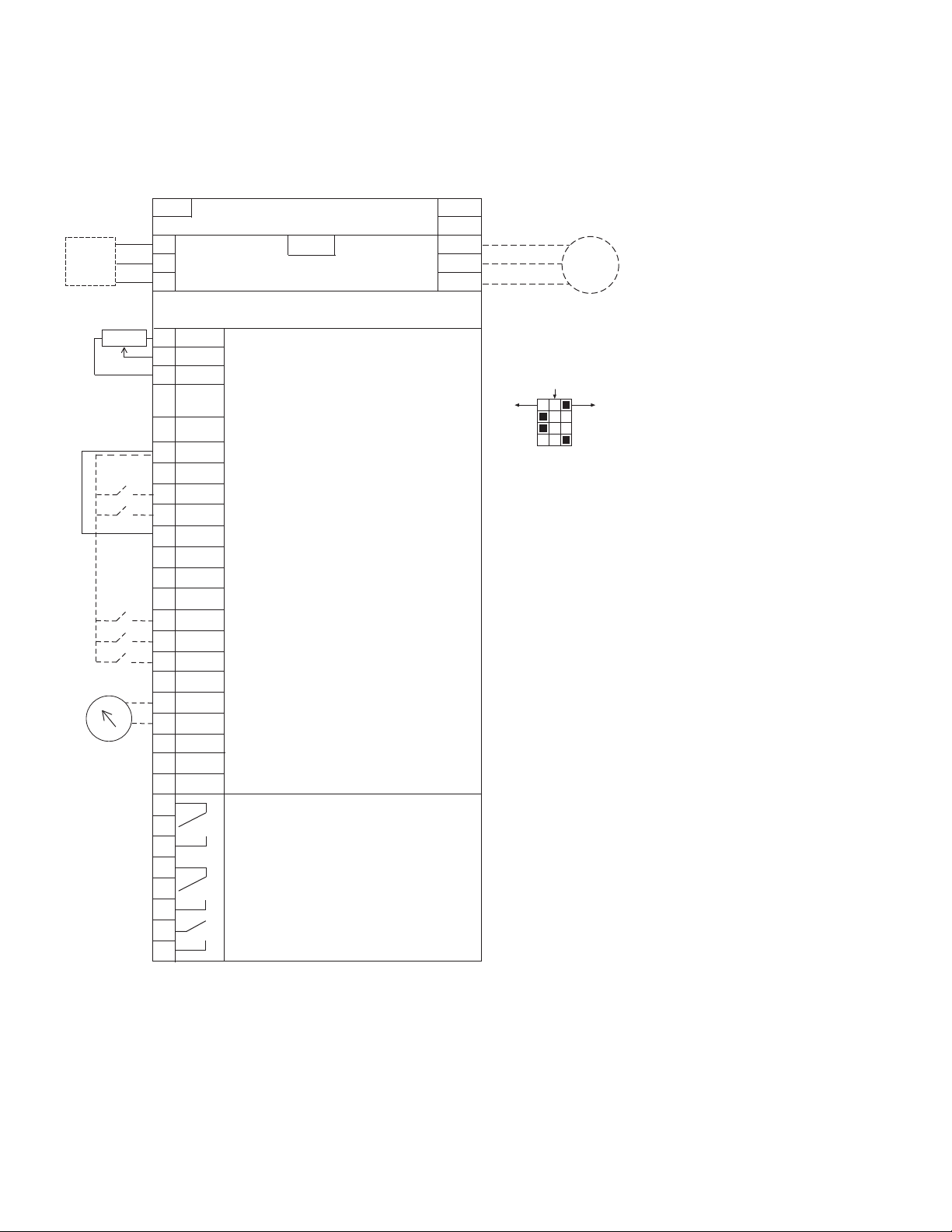
Example of Control Connections
Control Connections
BACnet/IP Ethernet Industrial Protocol
RJ-45
Modbus/TCP Transmission Control Protocol (Ethernet Based)
Optional
L1
Circuit
Breaker
Resistor
Factory
Jumper
Analog
Three-Phase Input
Input
L2
(Single-Phase not available)
L3
Slot A
Terminal
1
+10V
AI–1+
2
3
Vin
4
AI–2+
5
AI–2–
6
24V
GND
7
8
DIN1
9
DIN2
10
DIN3
COM
11
12
24Vout
GND
13
14
DIN4
DIN5
15
16
DIN6
CMB
17
18
AO–1+
19
AO–1–
30
24 VdcinAuxiliary Input Voltage
DATA –
A
B
DATA +
21
22
Factory Default Signal
Reference Output
Analog Input Voltage (Range 0–10 Vdc)
(can be programmed to current 4–20 mA)
Analog Output Common (Ground)
Analog Input Current (Range 4–20 mA)
(can be programmed to voltage 0–10 Vdc)
PI Setpoint or Feedback
Analog Input Common
PI Setpoint or Feedback
out
Control Voltage Output (0.1A max.)
I/O Ground
START/STOP (Contact closed = start)
External Fault (Closed = fault)
Run Interlock Permissive IP Interlock
(Closed = OK)
DIN1–DIN6 Common
Control Voltage Output (0.1A max.)
I/O Ground
Speed Select 0–100% (Preset speed)
Fire Mode (Contact closed = fire mode)
Force Bypass (Contact closed = bypass)
DIN1–DIN6 Common
Output Frequency (0–20 mA)
Analog Output Common (Ground)
RS-485 DATA–
RS-485 DATA+
Relay Board 1
Default Signal
RO1 Bypass Run
23
24
25
RO2 Drive Run
26
32
33
RO3 Fault
5% DC Link
Reactor
Three-Phase
Programmable BACnet,
Modbus, N2
Slot B
24 Vdc/8A
250 Vac/8A
125 Vdc/0.4A
DB
Chopper
Output
R+
R–
U (T1)
V (T2)
W (T3)
ON
CURRENT
CURRENT
CURRENT
Test
Motor
OFF
VOLTAGE
VOLTAGE
VOLTAGE
RS485
AO1
AI2
AI1
2 VSD Series II LIT-12011773—October 2012 www.johnsoncontrols.com
Keypad of the Drive
Keypad of the Drive
The control keypad is the interface between the Johnson
Controls VSD Series II frequency converter and the user.
With the control keypad it is possible to control the speed of
a motor, to supervise the state of the equipment and to set
the frequency converter’s parameters.
There are two different keypads used with the Series II drive.
The North American Keypad is slightly different than the
EMEA Keypad. Functionality is quite similar. The EMEA
keypad does not support the bypass functionality commonly
used in the United States.
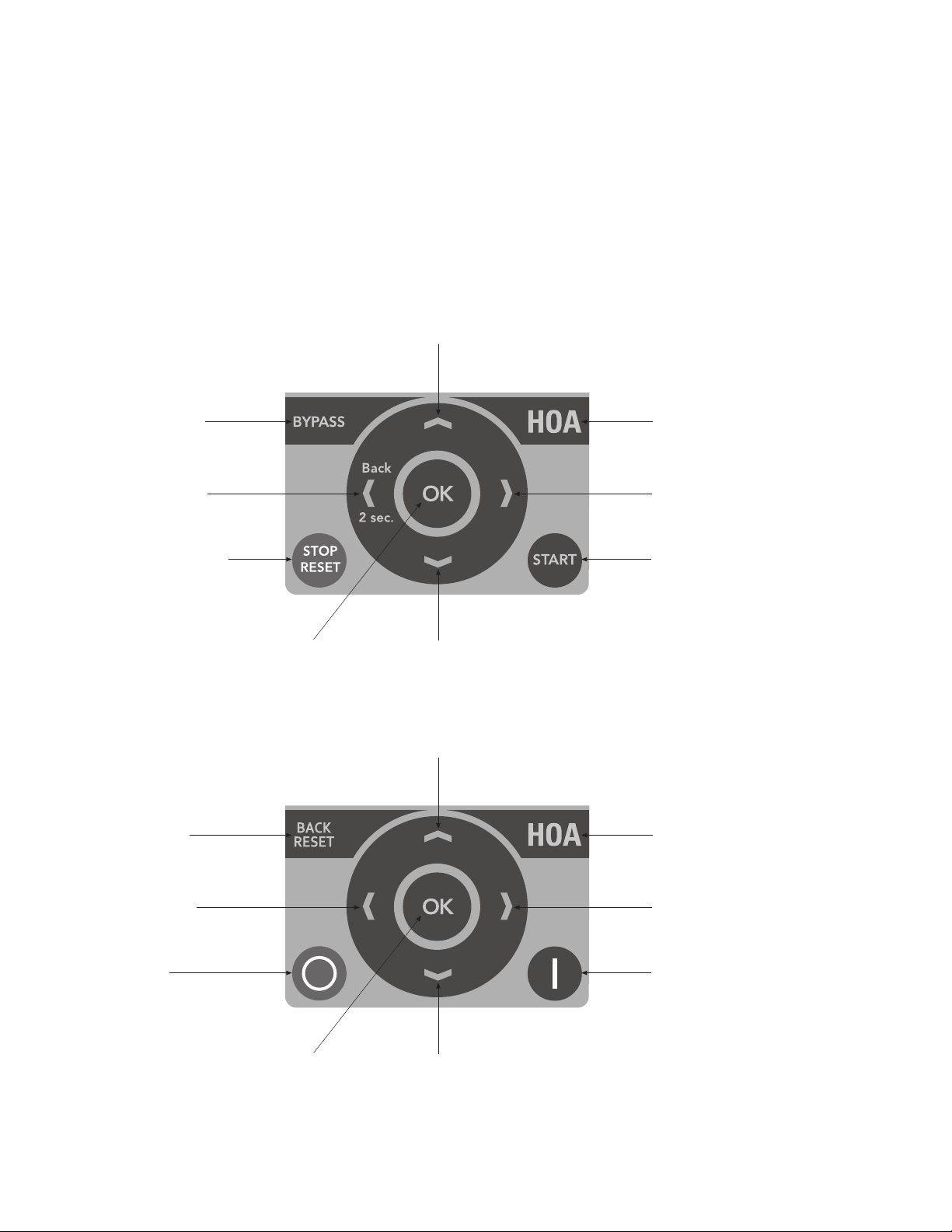
US Keypad Buttons
Increase Value
Scroll Menu Up
Switching Between
Drive and Bypass
Move Cursor Left
Back when Pressed
for two Seconds
Stop Button/Fault Reset Start Button
Change Control Place
Between Hand-Off-Auto
Move Cursor Right
Enter Menu
Confirm Selection
Decrease Value
Scroll Menu Down
EMEA Keypad Buttons
Increase Value
Scroll Menu Up
Back Fault Reset
Move Cursor Left
Stop Button Start Button
Enter Menu
Confirm Selection
Decrease Value
Scroll Menu Down
Change Control Place
Between Hand-Off-Auto
Move Cursor Right
VSD Series II LIT-12011773—October 2012 www.johnsoncontrols.com 3
Keypad of the Drive
Keypad Display
The keypad display indicates the status of the motor and the drive and any irregularities in
motor or drive functions. On the display, the user sees information about his present location
in the menu structure and the item displayed.
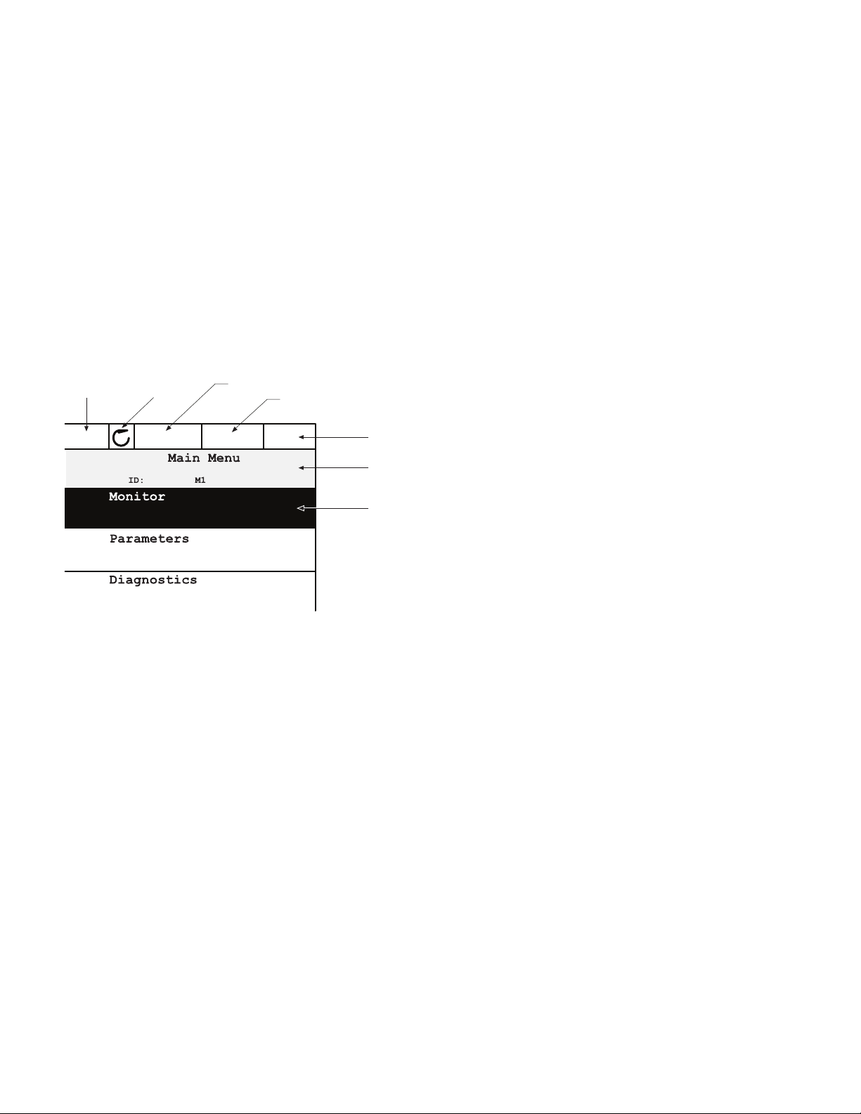
Main Menu
The data on the control keypad are arranged in menus and submenus. Use the up and down
arrows to move between the menus. Enter the group/item by pressing the OK button and
return to the former level by pressing the Back/Reset button.
The Location field indicates your current location. The Status field gives information about the
present status of the drive. See “Control Connections” on Page 2.
Main Menu
Status Field
STOP/RUN
Direction
Run Mode
Hand/Off/Auto
STOP
E-Energy Hand I/O
Control Place
PC/IO/KEYPAD/FIELDBUS
Location Field
(Parameter ID number and
current menu location)
Activated Group/Item
Press OK to Enter
Using the Graphical Keypad
Editing Values
Change value of a parameter following the procedure below:
1. Locate the parameter.
2. Enter the Edit mode.
3. Set new value with the up/down arrow buttons. You can also move from digit to digit
with the arrow buttons left/right if the value is numerical and then change the value with
the up/down arrow buttons.
4. Confirm change with OK button or ignore change by returning to previous level with
Back/Reset button.
4 VSD Series II LIT-12011773—October 2012 www.johnsoncontrols.com

Editing Values on Graphical Keypad
Keypad of the Drive
STOP READY I/O
STOP READY I/O
OK OK
STOP READY I/O
OR:
HOA Control Button
The HOA (Hand-Off-Auto) button is used for two functions:
to quickly access the Control page and to easily change
between the Hand (Keypad), Off, and Auto (Remote) control
places.
Control Place
The control place is the source of control where the drive can
be started and stopped. Every control place has its own
parameter for selecting the frequency reference source. In
the HVAC drive, the Hand control place is always the keypad.
The Auto control place is determined by parameter P2.1.1
(Keypad, I/O Terminal, I/O three-wire, or Fieldbus CTRL). The
selected control place can be seen on the status bar of the
keypad.
STOP READY I/O
OK
BACK
RESET
STOP READY I/O
Changing Control Place
Change of control place from Hand to Auto (keypad).
1. Anywhere in the menu structure, push the HOA button.
2. Push the arrow up or the arrow down button to select
Hand/Off/Auto and confirm with the OK button.
3. On the next display, select Hand, Off, or Auto and again
confirm with the OK button.
4. The display will return to the same location as it was
when the HOA button was pushed. However, if the
Remote control place was changed to Hand (Keypad)
you will be prompted for keypad reference.
Local Control
The keypad is always used as control place while in hand
control. Hand control has higher priority than auto control.
Therefore, if, for example, bypassed by parameter P2.1.17
through digital input while in Remote, the control place will
still switch to Keypad if Hand is selected. Switching between
Hand, Off, and Auto Control can be done by pressing the
HOA button on the keypad.
VSD Series II LIT-12011773—October 2012 www.johnsoncontrols.com 5

Keypad of the Drive
Accessing the Control Page
The Control page is meant for easy operation and monitoring of the most essential values.
1. Anywhere in the menu structure, push the HOA button.
2. Push the arrow up or the arrow down button to select Control page and confirm with the
OK button.
3. The control page appears. If keypad control place and keypad reference are selected to
be used, you can set the Keypad reference after having pressed the OK button. If other
control places or reference values are used, the display will show Frequency reference
which is not editable. The other values on the page are Multimonitoring values. You can
choose which values appear here for monitoring (for this procedure, see Application
Manual).
Accessing Control Page
STOP READY I/O
HOA
STOP READY Keypad
Edit
STOP READY Keypad
OK
STOP READY Keypad
0.00 Hz
OK
Help Texts
The graphical keypad features instant help and information displays for various items.
All parameters offer an instant help display. Select Help and press the OK button.
Text information is also available for faults, alarms and the Startup Wizard.
Help Text Example
STOP READY I/O STOP READY I/O
STOP READY I/O
0.00 Hz
OK
OK OK
6 VSD Series II LIT-12011773—October 2012 www.johnsoncontrols.com

Johnson Controls Series II—Startup
Startup Wizard
In the Startup Wizard, you will be prompted for essential
information needed by the drive so that it can start
controlling your process. In the Wizard, you will need the
following keypad buttons:
Left/Right arrows. Use these to easily move
between digits and decimals.
Up/Down arrows. Use these to move between
options in menu and to change value.
OK
BACK
RESET
Once you have connected power to your Johnson Controls
Series II frequency converter, follow these instructions to
easily set up your drive.
1
2
3
4
5
6
Note
OK button. Confirm selection with this button.
Back/Reset button. Pressing this button, you can
return to the previous question in the Wizard. If
pressed at the first question, the Startup Wizard will
be cancelled.
Run Startup Wizard Yes
Language Select Depends on language package
Daylight Saving
Time
Day
Year
These questions appear if battery is installed.
No
Russia
US
EU
OFF
hh:mm:ss
dd.mm.
yyyy
Johnson Controls Series II—Startup
7
8
9
10
11
12
13
14
15
16
17
18
19
20
Now the Startup Wizard is done.
The Startup Wizard can be re-initiated by pressing and
holding the back/reset button for two seconds. The Startup
Wizard will appear upon next power up.
Application Standard
PID
Multi-Pump
Bypass Enabled
Disabled
Motor Nominal Current Min: 0.26A
Max: Drive Dependent
Motor Nominal Voltage Min: 180.0V
Max: 690.0V
Motor Nominal Frequency Min: 8 Hz
Max: 320 Hz
Motor Nominal Speed Min: 24 RPM
Max: 19200 RPM
Min Frequency Min: 0 Hz
Max: 60 Hz
Max Frequency Min: 12 Hz
Max: 320 Hz
Accel Time 1 Min: 0.1s
Max: 3000s
Decel Time 1 Min: 0.1s
Max: 3000s
StartSourceHand Keypad
FieldbusCTRL
I/O Three-Wire
I/O Terminal
StartSourceAuto I/O Terminal
Keypad
FieldbusCTRL
I/O Three-Wire
SpeedSetptHand Keypad Ref
P1D1 Activated
AI1 + AI2
AI2
AI1
Fieldbus
SpeedSetptAuto PID1 Activated
AI1 + AI2
AI2
AI1
Fieldbus
Keypad Ref
VSD Series II LIT-12011773—October 2012 www.johnsoncontrols.com 7

Johnson Controls Series II—Startup
PID Mini-Wizard
The PID Mini-Wizard is activated in the Quick Setup menu.
This Wizard presupposes that you are going to use the PID
controller in the “one feedback/one setpoint” mode. The
control place will be I/O A and the default process unit “%”.
The PID Mini-Wizard asks for the following values to be set:
1
2
3
FeedBack1 Srce AI2
AI1
Not Used
ProceDataIn8
ProceDataIn7
ProceDataIn6
ProceDataIn5
ProceDataIn4
ProceDataIn3
ProceDataIn2
ProceDataIn1
AI6
AI5
AI4
AI3
Process Unit Selection (Several Selections)
Process Unit Min —
Multi-Pump
If Multi-Pump is the selected application, parameter group
2.16 will be visible in the menu structure. Default values may
need to be adjusted to meet your application needs.
Parameter
Group Name
Parameter Group 2.16:
Multi-Pump
Parameter
Number
P2.16.1 Number of motors
P2.16.2 Interlock function
P2.16.3 Include FC
P2.16.4 Autochange
P2.16.5 Autochange interval
P2.16.6 Autochange frequency limit
P2.16.7 Autochange motor limit
P2.16.8 Bandwidth
P2.16.9 Bandwidth delay
Parameter
Name
4
5
6
7
Process Unit Max —
P-Gain Min: 0%
Max: 200%
Integration Time Min: 0.00s
Max: 600.00s
SetPT1 Source Keypad SP1
Not Used
ProceDataIn8
ProceDataIn7
ProceDataIn6
ProceDataIn5
ProceDataIn4
ProceDataIn3
ProceDataIn2
ProceDataIn1
AI6
AI5
AI4
AI3
AI2
AI1
8 VSD Series II LIT-12011773—October 2012 www.johnsoncontrols.com

Menu Structure
For more information, the complete Application Manual can be referenced at:
http://www.johnsoncontrols.com —> HVAC Controls —> Variable Speed Drives.
Keypad Menus
Monitor Basic Diagnostics Active Faults
Timer Functions Reset Faults
Multimonitor Fault History
Parameters Basic Parameters Total Counters
Analog Inputs Trip Counters
Digital Inputs Software Info
Analog Outputs I/O & Hardware Basic I/O
Digital Outputs Slot D
Drive Control Slot E
Motor Control Real Time Clock
Protections Power Unit Settings
Fixed Frequencies Keypad
Fire Mode RS485
Multi-Pump —
Braking Ethernet
Fieldbus User Settings —
Second Parameter Set Favorites —
Timer Functions
Menu Structure
VSD Series II LIT-12011773—October 2012 www.johnsoncontrols.com 9

Parameter List
Parameter List
Parameter Group Name Parameter Number Parameter Name ID
Parameter Group 2.1—Basic Parameters
Basic P2.1.1 Application 213
P2.1.2 ByPass 214
P2.1.3 HOA Control Stc 1359
P2.1.4 Start Srce Hand 1300
P2.1.5 Speed Setpt Hand 1301
P2.1.6 Start Srce Auto 1302
P2.1.7 Speed Setpt Auto 1303
P2.1.8 Min Frequency 101
P2.1.9 Max Frequency 102
P2.1.10 Accel Time 1 103
P2.1.11 Decel Time 1 104
P2.1.12 Motor Nom Currnt 113
P2.1.13 Motor Nom Voltg 110
P2.1.14 Motor Nom Freq 111
P2.1.15 Motor Nom Speed 112
P2.1.16 MotorPowerFactor 120
P2.1.17 Current Limit 107
P2.1.18 Service Factor 1357
Parameter Group 2.2—Analog Inputs
Analog Input 1 P2.2.1.1 AI1 Signal selection 377
P2.2.1.2 AI1 Signal Inv 387
P2.2.1.3 AI1 Signal Range 379
P2.2.1.4 AI1 Custom Min 380
P2.2.1.5 AI1 Custom Max 381
P2.2.1.6 AI1 Filter Time 378
Analog Input 2 P2.2.2.1 AI2 Signal selection 388
P2.2.2.2 AI2 Signal Inv 398
P2.2.2.3 AI2 Signal Range 390
P2.2.2.4 AI2 Custom Min 391
P2.2.2.5 AI2 Custom Max 392
P2.2.2.6 AI2 Filter Time 389
Analog Input 3 P2.2.3.1 AI3 Signal selection 141
P2.2.3.2 AI3 Signal Inv 151
P2.2.3.3 AI3 Signal Range 143
P2.2.3.4 AI3 Custom Min 144
P2.2.3.5 AI3 Custom Max 145
P2.2.3.6 AI3 Filter Time 142
10 VSD Series II LIT-12011773—October 2012 www.johnsoncontrols.com

Parameter List
Parameter Group Name Parameter Number Parameter Name ID
Parameter Group 2.2—Analog Inputs, continued
Analog Input 4 P2.2.4.1 AI4 Signal selection 152
P2.2.4.2 AI4 Signal Inv 162
P2.2.4.3 AI4 Signal Range 154
P2.2.4.4 AI4 Custom Min 155
P2.2.4.5 AI4 Custom Max 156
P2.2.4.6 AI4 Filter Time 153
Analog Input 5 P2.2.5.1 AI5 Signal selection 188
P2.2.5.2 AI5 Signal Inv 198
P2.2.5.3 AI5 Signal Range 190
P2.2.5.4 AI5 Custom Min 191
P2.2.5.5 AI5 Custom Max 192
P2.2.5.6 AI5 Filter Time 189
Analog Input 6 P2.2.6.1 AI6 Signal selection 199
P2.2.6.2 AI6 Signal Inv 209
P2.2.6.3 AI6 Signal Range 201
P2.2.6.4 AI6 Custom Min 202
P2.2.6.5 AI6 Custom Max 203
P2.2.6.6 AI6 Filter Time 200
Parameter Group 2.2—Basic Parameters
Basic P2.2.7.1 Ref Scale Min. 1307
P2.2.7.2 Ref Scale Max. 1308
Parameter Group 2.3—Digital Inputs
Digital Input 1 P2.3.1.1 DI1 Open Invert Not accessible
P2.3.1.2 DI1 Function Not accessible
Digital Input 2 P2.3.2.1 DIN 2 Invert 1419
P2.3.2.2 DIN2 Function 1320
Digital Input 3 P2.3.3.1 DIN 3 Invert 1420
P2.3.3.2 DIN3 Function 1321
Digital Input 4 P2.3.4.1 DIN 4 Invert 1421
P2.3.4.2 DIN4 Function 1322
Digital Input 5 P2.3.5.1 DIN 5 Invert 1422
P2.3.5.2 DIN5 Function 1323
Digital Input 6 P2.3.6.1 DIN 6 Invert 1423
P2.3.6.2 DIN6 Function 1324
Digital Input Ext 1 P2.3.7.1 Ext-D1 Terminal 1325
P2.3.7.2 Ext-D1 Function 1326
Digital Input Ext 2 P2.3.8.1 Ext-D2 Terminal 1327
P2.3.8.2 Ext-D2 Function 1328
VSD Series II LIT-12011773—October 2012 www.johnsoncontrols.com 11

Parameter List
Parameter Group Name Parameter Number Parameter Name ID
Parameter Group 2.3—Basic Parameters
Basic P2.3.9.1 Start logic 1304
P2.3.9.2 INTLK Timeout 1305
P2.3.9.3 Delay Time 1306
P2.3.9.4 Intrlk Stop Mode 1356
P2.3.9.5 Interlock 1 Text 1315
P2.3.9.6 Interlock 2 Text 1316
P2.3.9.7 Interlock 3 Text 1317
Parameter Group 2.4—Analog Outputs
Analog Output 1 P2.4.1.1 AO1 Function 10050
P2.4.1.2 AO1 Filter Time 10051
P2.4.1.3 AO1 Min Signal 10052
P2.4.1.4 AO1 MinScale 10053
P2.4.1.5 AO1 MaxScale 10054
P2.4.1.6 AO1 Invert 10060
Parameter Group 2.5—Digital Outputs
Digital Output 1 P2.5.1.1 RO1 function 11001
P2.5.1.2 RO1 Invert 11020
P2.5.1.3 RO1 ON delay 11002
P2.5.1.4 RO1 OFF delay 11003
Digital Output 2 P2.5.2.1 RO2 function 11004
P2.5.2.2 RO2 Invert 11021
P2.5.2.3 RO2 ON delay 11005
P2.5.2.4 RO2 OFF delay 11006
Digital Output 3 P2.5.3.1 RO3 function 11007
Supervision P2.5.9.1 Superv1 Item 1622
P2.5.9.2 Supervision #1 mode 1623
P2.5.9.3 Supervision #1 limit 1624
P2.5.9.4 Supervision #1 limit hysteresis 1625
P2.5.9.5 Superv2 Item 1626
P2.5.9.6 Supervision #2 mode 1627
P2.5.9.7 Supervision #2 limit 1628
P2.5.9.8 Supervision #2 limit hysteresis 1629
12 VSD Series II LIT-12011773—October 2012 www.johnsoncontrols.com

Parameter List
Parameter Group Name Parameter Number Parameter Name ID
Parameter Group 2.6—Drive Control
Basic P2.6.1.1 Start Function 505
P2.6.1.2 Stop Function 506
P2.6.1.3 InhibitDirection 1336
P2.6.1.4 Reference Unit 1362
P2.6.1.5 Keypad Reference 184
P2.6.1.6 Keypad Direction 123
P2.6.1.7 Keypad Reference copy 181
P2.6.1.8 Keypad Stop Button 114
P2.6.1.9 Accel Time 2 502
P2.6.1.10 Decel Time 2 503
P2.6.1.11 RampselectMode 1333
P2.6.1.12 Accel2Threshold 526
P2.6.1.13 Decel2Threshold 1334
P2.6.1.14 S-Ramp 1 Shape 500
P2.6.1.15 S-Ramp 2 Shape 501
Skip Frequencies P2.6.2.1 Range 1 Low Lim 509
P2.6.2.2 Range 1 High Lim 510
P2.6.2.3 Range 2 Low Lim 511
P2.6.2.4 Range 2 High Lim 512
P2.6.2.5 Range 3 Low Lim 513
P2.6.2.6 Range 3 High Lim 514
P2.6.2.7 Range 4 Low Lim 1337
P2.6.2.8 Range 4 High Lim 1338
P2.6.2.9 Range 5 Low Lim 1339
P2.6.2.10 Range 5 High Lim 1340
P2.6.2.11 Range 6 Low Lim 1341
P2.6.2.12 Range 6 High Lim 1342
P2.6.2.13 RampTimeFactor 518
Parameter Group 2.7—Motor Control
Motor Control P2.7.1 V/Hz RatioSelect 108
P2.7.2 Field WeakngPnt 602
P2.7.3 Voltage at FWP 603
P2.7.4 V/Hz Mid Freq 604
P2.7.5 V/Hz Mid Voltage 605
P2.7.6 Zero Freq Voltg 606
P2.7.7 Switching Freq 601
VSD Series II LIT-12011773—October 2012 www.johnsoncontrols.com 13

Parameter List
Parameter Group Name Parameter Number Parameter Name ID
Parameter Group 2.8—Faults
Faults P2.8.1.1 AI Low Fault 700
P2.8.1.2 Undervoltage Flt 727
P2.8.1.3 OutputPhase Flt 702
P2.8.1.4 Motor Duty Cycle 708
P2.8.1.5 Underload Flt 713
P2.8.1.6 Motor Therm Prot 704
P2.8.1.7 MotAmbient Temp 705
P2.8.1.8 ZeroSpeedCooling 706
P2.8.1.9 ThermTimeConst 707
P2.8.1.10 Thermistor Fault 732
P2.8.1.11 External Fault 701
P2.8.1.12 FieldbusComm Flt 733
P2.8.1.13 InputPhaseFault 730
P2.8.1.14 MotorStall Flt 709
P2.8.1.15 PID1 Supervision 749
P2.8.1.16 PID2 Supervision 757
P2.8.1.17 SlotCommFlt 734
P2.8.1.18 Preset Alarm Freq 183
Automatic Reset P2.8.2.1 Automatic Reset 731
P2.8.2.2 Restart function 719
P2.8.2.3 Wait Time 717
P2.8.2.4 Trial Time 718
P2.8.2.5 Number of trials 759
P2.8.2.6 Undervoltage Flt 720
P2.8.2.7 Overvoltage Flt 721
P2.8.2.8 Overcurrent Flt 722
P2.8.2.9 AI Low Fault 723
P2.8.2.10 UnitOverTemp Flt 724
P2.8.2.11 MotorOverTempFlt 725
P2.8.2.12 External Fault 726
P2.8.2.13 IGBT temp 1358
14 VSD Series II LIT-12011773—October 2012 www.johnsoncontrols.com

Parameter List
Parameter Group Name Parameter Number Parameter Name ID
Parameter Group 2.9—PID Controller
PID Controller 1, Basic Settings P2.9.1.1.1 Gain, PID Controller 1 118
P2.9.1.1.2 Integration Time, PID Controller 1 119
P2.9.1.1.3 Derivation Time, PID Controller 1 132
P2.9.1.1.4 ProcessUnitSel, PID Controller 1 1036
P2.9.1.1.5 ProcessUnitMin, PID Controller 1 1033
P2.9.1.1.6 ProcessUnitMax, PID Controller 1 1034
P2.9.1.1.7 ProcessUnitDecimals, PID Controller 1 1035
P2.9.1.1.8 Error Inversion, PID Controller 1 340
P2.9.1.1.9 Dead Band, PID Controller 1 1056
P2.9.1.1.10 Dead band delay, PID Controller 1 1057
PID Controller 1, Setpoints P2.9.1.2.1 Keypad SP 1, PID Controller 1 167
P2.9.1.2.2 Keypad SP 2, PID Controller 1 168
P2.9.1.2.3 Ramp Time, PID Controller 1 1068
P2.9.1.2.4 SetPt 1 Source, PID Controller 1 332
P2.9.1.2.5 SetPt 1 min, PID Controller 1 1069
P2.9.1.2.6 SP 1 maximum, PID Controller 1 1070
P2.9.1.2.7 SP 1 Sleep Freq, PID Controller 1 1016
P2.9.1.2.8 SP 1 Sleep delay, PID Controller 1 1017
P2.9.1.2.9 SP 1 WakeUpLevel, PID Controller 1 1018
P2.9.1.2.10 SP 1 boost, PID Controller 1 1071
P2.9.1.2.11 SP 2 Source, PID Controller 1 431
P2.9.1.2.12 SP 2 minimum, PID Controller 1 1073
P2.9.1.2.13 SP 2 maximum, PID Controller 1 1074
P2.9.1.2.14 SP 2 Sleep Freq, PID Controller 1 1075
P2.9.1.2.15 SP 2 Sleep delay, PID Controller 1 1076
P2.9.1.2.16 SP 2 WakeUpLevel, PID Controller 1 1077
P2.9.1.2.17 SP 2 boost, PID Controller 1 1078
PID Controller 1, Feedbacks P2.9.1.3.1 Function, PID Controller 1 333
P2.9.1.3.2 Gain, PID Controller 1 1058
P2.9.1.3.3 FeedBack 1 Srce, PID Controller 1 334
P2.9.1.3.4 FB 1 Minimum, PID Controller 1 336
P2.9.1.3.5 FB 1 Maximum, PID Controller 1 337
P2.9.1.3.6 FB 2 Source, PID Controller 1 335
P2.9.1.3.7 FB 2 Minimum, PID Controller 1 338
P2.9.1.3.8 FB 2 Maximum, PID Controller 1 339
PID Controller 1, Feedforward P2.9.1.4.1 Function, PID Controller 1 1059
P2.9.1.4.2 Gain, PID Controller 1 1060
P2.9.1.4.3 FF 1 Source, PID Controller 1 1061
P2.9.1.4.4 FF1 Minimum, PID Controller 1 1062
P2.9.1.4.5 FF1 Maximum, PID Controller 1 1063
P2.9.1.4.6 FF 2 Source, PID Controller 1 1064
P2.9.1.4.7 FF2 Minimum, PID Controller 1 1065
P2.9.1.4.8 FF2 Maximum, PID Controller 1 1066
VSD Series II LIT-12011773—October 2012 www.johnsoncontrols.com 15

Parameter List
Parameter Group Name Parameter Number Parameter Name ID
Parameter Group 2.9—PID Controller, continued
PID Controller 1, Process Supervision P2.9.1.5.1 Enable Superv, PID Controller 1 735
P2.9.1.5.2 Upper limit, PID Controller 1 736
P2.9.1.5.3 Lower limit, PID Controller 1 758
P2.9.1.5.4 Delay, PID Controller 1 737
PID Controller 1, Pressure Loss Compensation P2.9.1.6.1 Enable SP 1, PID Controller 1 1529
P2.9.1.6.2 SP 1 Max Comp., PID Controller 1 1530
P2.9.1.6.3 Enable SP 2, PID Controller 1 1531
P2.9.1.6.4 SP 2 Max Comp., PID Controller 1 1532
PID Controller 2, Basic Settings P2.9.2.1.1 Gain, PID Controller 2 1631
P2.9.2.1.2 Integration Time, PID Controller 2 1632
P2.9.2.1.3 Derivation Time, PID Controller 2 1633
P2.9.2.1.4 ProcessUnitSel, PID Controller 2 1635
P2.9.2.1.5 ProcessUnitMin, PID Controller 2 1664
P2.9.2.1.6 ProcessUnitMax, PID Controller 2 1665
P2.9.2.1.7 ProcessUnitDecimals, PID Controller 2 1666
P2.9.2.1.8 Error Inversion, PID Controller 2 1636
P2.9.2.1.9 Dead Band, PID Controller 2 1637
P2.9.2.1.10 Dead band delay, PID Controller 2 1638
PID Controller 2, Setpoints P2.9.2.2.1 Keypad SP 1, PID Controller 2 1640
P2.9.2.2.2 Keypad SP 2, PID Controller 2 1641
P2.9.2.2.3 Ramp Time, PID Controller 2 1642
P2.9.2.2.4 SetPt 1 Source, PID Controller 2 1643
P2.9.2.2.5 SetPt 1 min, PID Controller 2 1644
P2.9.2.2.6 SP 1 maximum, PID Controller 2 1645
P2.9.2.2.7 SP 2 Source, PID Controller 2 1646
P2.9.2.2.8 SP 2 minimum, PID Controller 2 1647
P2.9.2.2.9 SP 2 maximum, PID Controller 2 1648
PID Controller 2, Feedbacks P2.9.2.3.1 Function, PID Controller 2 1650
P2.9.2.3.2 Gain, PID Controller 2 1651
P2.9.2.3.3 FeedBack 1 Srce, PID Controller 2 1652
P2.9.2.3.4 FB 1 Minimum, PID Controller 2 1653
P2.9.2.3.5 FB 1 Maximum, PID Controller 2 1654
P2.9.2.3.6 FB 2 Source, PID Controller 2 1655
P2.9.2.3.7 FB 2 Minimum, PID Controller 2 1656
P2.9.2.3.8 FB 2 Maximum, PID Controller 2 1657
PID Controller 2, Process Supervision P2.9.2.4.1 Enable Superv, PID Controller 2 1659
P2.9.2.4.2 Upper limit, PID Controller 2 1660
P2.9.2.4.3 Lower limit, PID Controller 2 1661
P2.9.2.4.4 Delay, PID Controller 2 1662
16 VSD Series II LIT-12011773—October 2012 www.johnsoncontrols.com

Parameter List
Parameter Group Name Parameter Number Parameter Name ID
Parameter Group 2.10—Fixed Frequencies
Fixed Frequencies P2.10.1 Preset Freq 1 105
P2.10.2 Preset Freq 2 106
P2.10.3 Preset Freq 3 126
P2.10.4 Preset Freq 4 127
P2.10.5 Preset Freq 5 128
P2.10.6 Preset Freq 6 129
P2.10.7 Preset Freq 7 130
Parameter Group 2.11—Fire Mode
Fire Mode P2.11.1 Firemode Freq 1598
Parameter Group 2.12—Multi-Pump
Multi-Pump P2.12.1 Number of motors 1001
P2.12.2 Interlock function 1032
P2.12.3 Include FC 1028
P2.12.4 Autochange 1027
P2.12.5 Autochange interval 1029
P2.12.6 Autochange: frequency limit 1031
P2.12.7 Autochange: motor limit 1030
P2.12.8 Bandwidth 1097
P2.12.9 Bandwidth delay 1098
Parameter Group 2.13—Braking
Braking P2.13.1 DC Brake Current 507
P2.13.2 DC Time Stop 508
P2.13.3 DC BrakeFreqStop 515
P2.13.4 StartMagnTime 516
P2.13.5 StartMagnCurrent 517
P2.13.6 Preheat Current 1335
Parameter Group 2.14—Fieldbus
Fieldbus P2.14.1 FB Data Out1 Sel 852
P2.14.2 FB Data Out2 Sel 853
P2.14.3 FB Data Out3 Sel 854
P2.14.4 FB Data Out4 Sel 855
P2.14.5 FB Data Out5 Sel 856
P2.14.6 FB Data Out6 Sel 857
P2.14.7 FB Data Out7 Sel 858
P2.14.8 FB Data Out8 Sel 859
Parameter Group 2.15—Second Param Set
Motor 2 P2.15.1.1 Motor Nom Currnt, Set2 1347
P2.15.1.2 Motor Nom Voltg, Set2 1348
P2.15.1.3 Motor Nom Freq, Set2 1349
P2.15.1.4 Motor Nom Speed, Set2 1350
P2.15.1.5 MotorPowerFactor, Set2 1351
P2.15.1.6 Current Limit, Set2 1352
P2.15.1.7 Motor Therm Prot, Set2 1353
VSD Series II LIT-12011773—October 2012 www.johnsoncontrols.com 17

Parameter List
Parameter Group Name Parameter Number Parameter Name ID
Parameter Group 2.15—Second Param Set, continued
Drive Control 2 P2.15.2.1 Min Frequency, Set2 1343
P2.15.2.2 Max Frequency, Set2 1344
P2.15.2.3 Accel Time 1, Set2 1345
P2.15.2.4 Decel Time 1, Set2 1346
P2.15.2.5 V/Hz RatioSelect, Set2 1355
Parameter Group 2.16—Timer Functions
Interval 1 P2.16.1.1 ON Time, Interval 1 1670
P2.16.1.2 Off Time, Interval 1 1671
P2.16.1.3 From Day, Interval 1 1672
P2.16.1.4 To Day, Interval 1 1673
P2.16.1.5 Assign to channel, Interval 1 1674
Interval 2 P2.16.2.1 ON Time, Interval 2 1675
P2.16.2.2 Off Time, Interval 2 1676
P2.16.2.3 From Day, Interval 2 1677
P2.16.2.4 To Day, Interval 2 1678
P2.16.2.5 Assign to channel, Interval 2 1679
Interval 3 P2.16.3.1 ON Time, Interval 3 1680
P2.16.3.2 Off Time, Interval 3 1681
P2.16.3.3 From Day, Interval 3 1682
P2.16.3.4 To Day, Interval 3 1683
P2.16.3.5 Assign to channel, Interval 3 1684
Interval 4 P2.16.4.1 ON Time, Interval 4 1685
P2.16.4.2 Off Time, Interval 4 1686
P2.16.4.3 From Day, Interval 4 1687
P2.16.4.4 To Day, Interval 4 1688
P2.16.4.5 Assign to channel, Interval 4 1689
Interval 5 P2.16.5.1 ON Time, Interval 5 1690
P2.16.5.2 Off Time, Interval 5 1691
P2.16.5.3 From Day, Interval 5 1692
P2.16.5.4 To Day, Interval 5 1693
P2.16.5.5 Assign to channel, Interval 5 1694
Timer 1 P2.16.6.1 Duration 1695
P2.16.6.2 Assign to channel 1696
Timer 2 P2.16.7.1 Duration 1697
P2.16.7.2 Assign to channel 1698
Timer 3 P2.16.8.1 Duration 1699
P2.16.8.2 Assign to channel 1700
18 VSD Series II LIT-12011773—October 2012 www.johnsoncontrols.com

Diagnostics
Diagnostics
Under this menu, you can find Active faults, Reset faults, Fault history, Counters and Software info.
Active Faults
Menu Function Note
Active faults When a fault/faults appear(s), the display with the name of
the fault starts to blink. Press OK to return to the
Diagnostics menu. The Active faults submenu shows the
number of faults. Select the fault and push OK to see the
fault-time data.
Reset Faults
Menu Function Note
Reset faults In this menu you can reset faults. For closer instructions. CAUTION! Remove external Control signal before
The fault remains active until it is cleared with the Reset
button (push for 2s) or with a reset signal from the I/O
terminal or Fieldbus or by choosing Reset faults (see
below). The memory of active faults can store the
maximum of 10 faults in the order of appearance.
resetting the fault to prevent unintentional restart
of the drive.
Fault History
Menu Function Note
Fault history 40 latest faults are stored in the Fault history. Entering the Fault history and clicking OK on the selected
fault shows the fault time data (details).
Fault Codes
Fault Codes and Descriptions
Fault
Code
1 1 Overcurrent
2 10 Overvoltage
3 20 Earth fault
5 40 Charging switch The charging switch is open, when the
Fault
ID Fault Name Possible Cause Remedy
(hardware fault)
2 Overcurrent
(software fault)
(hardware fault)
11 Overvoltage
(software fault)
(hardware fault)
21 Earth fault
(software fault)
AC drive has detected too high a current
) in the motor cable:
(>4*I
H
• Sudden heavy load increase
• Short circuit in motor cables
• Unsuitable motor
The DC-link voltage has exceeded the
limits defined:
• Too short a deceleration time
• Brake chopper is disabled
• High overvoltage spikes in supply
• Start/Stop sequence too fast
Current measurement has detected that
the sum of motor phase current is not zero:
• Insulation failure in cables or motor
START command has been given:
• Faulty operation
• Component failure
• Check loading
• Check motor
• Check cables and connections
• Make identification run
• Check ramp times
• Make deceleration time longer
• Use brake chopper or brake resistor
(available as options)
• Activate overvoltage controller
• Check input voltage
Check motor cables and motor
• Reset the fault and restart
• Should the fault re-occur, contact the
distributor near to you
VSD Series II LIT-12011773—October 2012 www.johnsoncontrols.com 19

Diagnostics
Fault Codes and Descriptions, continued
Fault
Code
7 60 Saturation Various causes:
8 600 System fault Communication between control board
9 80 Undervoltage
10 91 Input phase Input line phase is missing Check supply voltage, fuses and cable
11 100 Output phase
Fault
ID Fault Name Possible Cause Remedy
• Cannot be reset from keypad
• Defective component
• Brake resistor short-circuit or overload
and power unit has failed
602 Watchdog has reset the CPU
603 Voltage of auxiliary power in power unit
604 Phase fault: Voltage of an output phase
605 CPLD has faulted but there is no detailed
606 Control and power unit software are
607 Software version cannot be read. There is
608 CPU overload. Some part of the software
609 Memory access has failed. For example,
610 Necessary device properties cannot be read
647 Software error Update software. Should the fault re-occur,
648 Invalid function block used in application.
649 Resource overload:
(fault)
81 Undervoltage
(alarm)
supervision
is too low
does not follow the reference
information about the fault
incompatible
no software in power unit
(for example application) has caused an
overload situation. The source of fault
has been suspended
retain variables could not be restored
System software and application are not
compatible
• Error when loading parameter initial
values
• Error when restoring parameters
• Error when saving parameters
DC link voltage is under the voltage limits
defined:
• Most probable cause: Too low a supply
voltage
• AC drive internal fault
• Defect input fuse
• External charge switch not closed
Note: This fault is activated only if the drive
is in Run state.
Current measurement has detected that there
is no current in one motor phase
• Switch off power
• DO NOT RECONNECT POWER! Contact
factory
• If this fault appears simultaneously with
F1, check motor cables and motor
Reset the fault and restart. Should the fault
re-occur, contact the distributor near you
Update software. Should the fault re-occur,
contact the distributor near you
Update power unit software. Should the fault
re-occur, contact the distributor near you
Reset the fault and restart. Should the fault
re-occur, contact the distributor near you
contact the distributor near you
In case of temporary supply voltage break reset
the fault and restart the AC drive. Check the
supply voltage. If it is adequate, an internal
failure has occurred. Contact the distributor
near you
Check motor cable and motor
20 VSD Series II LIT-12011773—October 2012 www.johnsoncontrols.com

Diagnostics
Fault Codes and Descriptions, continued
Fault
Code
12 110 Brake chopper supervision
13 120 AC drive undertemperature
14 130 AC drive overtemperature
15 140 Motor stalled Motor is stalled Check motor and load
16 150 Motor overtemperature Motor is overloaded Decrease motor load. If no motor overload
17 160 Motor underload Motor is underloaded Check load
19 180 Power overload
25 — Motor control fault Start angle identification has failed.
32 312 Fan cooling Fan lifetime is up Change fan and reset fan lifetime counter
33 — Fire mode enabled Fire mode of the drive is enabled. The
37 360 Device changed
38 370 Device changed
39 380 Device removed Optional board removed from slot Device no longer available
40 390 Device unknown Unknown device connected (power
41 400 IGBT temperature IGBT temperature (unit temperature + I
43 420 Encoder fault Encoder 1 channel A is missing • Check encoder connections
Fault
ID Fault Name Possible Cause Remedy
(hardware fault)
111 Brake chopper
saturation alarm
(fault)
121 AC drive overtemperature
(alarm)
(fault, heatsink)
131 AC drive overtemperature
(alarm, heatsink)
132 AC drive overtemperature
(fault, board)
133 AC drive overtemperature
(alarm, board)
(short-time supervision)
181 Power overload
(long-time supervision)
(same type)
(same type)
421 Encoder 1 channel B is missing
422 Both encoder 1 channels are missing
423 Encoder reversed
424 Encoder board missing
• No brake resistor installed
• Brake resistor is broken
• Brake chopper failure
Too low temperature measured in power
unit’s heatsink or board. Heat- sink
temperature is under –10°C
Too high temperature measured in power
unit’s heatsink or board. Heat- sink
temperature is over 100°C
Drive power is too high Decrease load
Generic motor control fault
drive’s protections are not in use
Option board changed for one previously
inserted in the same slot. The board’s
parameter settings are saved
Option board added. The option board was
previously inserted in the same slot. The
board’s parameter settings are saved
unit/option board)
is too high
2
Check brake resistor and cabling. If these are
OK, the chopper is faulty. Contact the
distributor near you
—
• Check the correct amount and flow of
cooling air
• Check the heatsink for dust
• Check the ambient temperature
• Make sure that the switching
frequency is not too high in relation to
ambient temperature and motor load
exists, check the temperature model
parameters
—
—
Device is ready for use. Old parameter settings
will be used
Device is ready for use. Old parameter settings
will be used
Device no longer available
T)
• Check loading
• Check motor size
• Make identification run
• Check encoder and encoder cable
• Check encoder board
• Check encoder frequency in open loop
VSD Series II LIT-12011773—October 2012 www.johnsoncontrols.com 21

Diagnostics
Fault Codes and Descriptions, continued
Fault
Code
44 430 Device changed
45 440 Device changed
51 1051 External fault Digital input —
52 1052 Keypad communication
53 1053 Fieldbus communication
54 1354 Slot A fault Defective option board or slot Check board and slot
65 1065 PC communication fault The data connection between the PC and
66 1066 Thermistor fault The thermistor input has detected an
69 1310 Fieldbus mapping error Non-existing ID number is used for
101 1101 Process supervision fault
105 1105 Process supervision fault
Fault
ID Fault Name Possible Cause Remedy
(different type)
(different type)
1352
1454 Slot B fault
1654 Slot D fault
1754 Slot E fault
1311 Not possible to convert one or more
1312 Overflow when mapping and converting
fault
fault
(PID1)
(PID2)
Option board changed for one not present
in the same slot before. No parameter
settings are saved
Option board added. The option board was
not previously present in the same slot. No
parameter settings are saved
The connection between the control
keypad and frequency converter is broken
The data connection between the Fieldbus
master and Fieldbus board is broken
frequency converter is broken
increase of motor temperature
mapping values to Fieldbus Process
Data Out
values for Fieldbus Process Data Out
values for Fieldbus Process Data Out
(16-bit)
PID controller: Feedback value outside
of supervision limits (and the delay if set)
PID controller: Feedback value outside
of supervision limits (and the delay if set)
Set the option board parameters again
Set the option board parameters again
Check keypad connection and possible keypad
cable
Check installation and Fieldbus master
—
• Check motor cooling and load
• Check thermistor connection (if
thermistor input is not in use it has to
be short circuited)
Check parameters in Fieldbus Data Mapping
menu
The value being mapped may be of undefined
type. Check parameters in Fieldbus Data
Mapping menu
—
—
—
22 VSD Series II LIT-12011773—October 2012 www.johnsoncontrols.com

Diagnostics
VSD Series II LIT-12011773—October 2012 www.johnsoncontrols.com 23

Diagnostics
24 VSD Series II LIT-12011773—October 2012 www.johnsoncontrols.com


Controls Group
507 E. Michigan Street
P.O. Box 423
Milwaukee, WI 53201
Powered by
Eaton Technology
© 2012 Johnson Controls
All Rights Reserved
Printed in USA
Publication No. LIT-12011773 / Z12052
October 2012
 Loading...