

Johnson Controls VS3-326D6EB-C20C, VS3-324D8DN-C21C, VS3-327D8EB-C20C, VS3-324D8EB-C20C, VS3-327D8DN-C21C Applications Manual
...Page 1

Variable Speed Drive Series III
Application manual
Effective June 2018
Supersedes March 2018
Supports Firmware Version Bundle:
DH1-V0003-JCI
Page 2

Variable Speed Drive Series III
Disclaimer of warranties and limitation of liability
The information, recommendations, descriptions, and safety notations in this document are based on Johnson Controls’
experience and judgment and may not cover all contingencies. If further information is required, a Johnson Controls sales
office should be consulted. Sale of the product shown in this literature is subject to the terms and conditions outlined in
appropriate Johnson Controls selling policies or other contractual agreement between Johnson Controls and the purchaser.
THERE ARE NO UNDERSTANDINGS, AGREEMENTS, WARRANTIES, EXPRESSED OR IMPLIED, INCLUDING WARRANTIES
OF FITNESS FOR A PARTICULAR PURPOSE OR MERCHANTABILITY, OTHER THAN THOSE SPECIFICALLY SET OUT IN ANY
EXISTING CONTRACT BETWEEN THE PARTIES. ANY SUCH CONTRACT STATES THE ENTIRE OBLIGATION OF JOHNSON
CONTROLS. THE CONTENTS OF THIS DOCUMENT SHALL NOT BECOME PART OF OR MODIFY ANY CONTRACT
BETWEEN THE PARTIES.
In no event will Johnson Controls be responsible to the purchaser or user in contract, in tort (including negligence), strict
liability, or otherwise for any special, indirect, incidental, or consequential damage or loss whatsoever, including but not
limited to damage or loss of use of equipment, plant or power system, cost of capital, loss of power, additional expenses
in the use of existing power facilities, or claims against the purchaser or user by its customers resulting from the use of the
information, recommendations, and descriptions contained herein. The information contained in this manual is subject to change
withoutnotice.
Cover Photo: Johnson Controls Variable Speed Drive Series III
ii
VARIABLE SPEED DRIVE SERIES III LIT-12012999—June 2018 www.johnsoncontrols.com
Page 3

Support services
Support services
The goal of Johnson Controls is to ensure your greatest
possible satisfaction with the operation of our products.
We are dedicated to providing fast, friendly, and accurate
assistance. That is why we offer you so many ways to get
the support you need. Whether it is by phone, fax, or email,
you can access Johnson Controls’ support information
24hours a day, seven days a week.
Our wide range of services is listed below.
You should contact your local distributor for product pricing,
availability, ordering, expediting, and repairs.
Website
Use the Johnson Controls website to find product
information.
Website address
www.johnsoncontrols.com –> HVAC Controls –> Variable
Speed Drives
Variable Speed Drive Series III
Johnson Controls product sales operation/
technical support
Call Local Service Center Representative.
If Representative is unknown, call 1-800-482-2778 and ask
for a local service rep for programming support.
VARIABLE SPEED DRIVE SERIES III LIT-12012999—June 2018 www.johnsoncontrols.com
iii
Page 4

Variable Speed Drive Series III
Table of contents
SAFETY
Before commencing the installation . . . . . . . . . . . . . . . . . . . . . . . . . . . . . . . . . . . . . . xv
Definitions and symbols . . . . . . . . . . . . . . . . . . . . . . . . . . . . . . . . . . . . . . . . . . . . . . xvi
Hazardous high voltage . . . . . . . . . . . . . . . . . . . . . . . . . . . . . . . . . . . . . . . . . . . . . . . xvi
Warnings and cautions . . . . . . . . . . . . . . . . . . . . . . . . . . . . . . . . . . . . . . . . . . . . . . . xvi
Important safety information . . . . . . . . . . . . . . . . . . . . . . . . . . . . . . . . . . . . . . . . . . . xvii
CHAPTER 1—VARIABLE SPEED DRIVES SERIES III OVERVIEW
How to use this manual . . . . . . . . . . . . . . . . . . . . . . . . . . . . . . . . . . . . . . . . . . . . . . . .1
Receiving and inspection . . . . . . . . . . . . . . . . . . . . . . . . . . . . . . . . . . . . . . . . . . . . . . . .1
Real time clock battery activation . . . . . . . . . . . . . . . . . . . . . . . . . . . . . . . . . . . . . . . . .1
Rating label . . . . . . . . . . . . . . . . . . . . . . . . . . . . . . . . . . . . . . . . . . . . . . . . . . . . . . . . . .2
Carton rating label . . . . . . . . . . . . . . . . . . . . . . . . . . . . . . . . . . . . . . . . . . . . . . . . . . . . .2
Catalog number system . . . . . . . . . . . . . . . . . . . . . . . . . . . . . . . . . . . . . . . . . . . . . . . .3
Power ratings and product selection . . . . . . . . . . . . . . . . . . . . . . . . . . . . . . . . . . . . . . .4
CHAPTER 2—KEYPAD OVERVIEW
Overview . . . . . . . . . . . . . . . . . . . . . . . . . . . . . . . . . . . . . . . . . . . . . . . . . . . . . . . . . . . .8
Keypad buttons . . . . . . . . . . . . . . . . . . . . . . . . . . . . . . . . . . . . . . . . . . . . . . . . . . . . . . .9
LED lights . . . . . . . . . . . . . . . . . . . . . . . . . . . . . . . . . . . . . . . . . . . . . . . . . . . . . . . . . .11
LCD display . . . . . . . . . . . . . . . . . . . . . . . . . . . . . . . . . . . . . . . . . . . . . . . . . . . . . . . . . 11
CHAPTER 3—MENU OVERVIEW
Main menu page . . . . . . . . . . . . . . . . . . . . . . . . . . . . . . . . . . . . . . . . . . . . . . . . . . . . .14
Menu navigation . . . . . . . . . . . . . . . . . . . . . . . . . . . . . . . . . . . . . . . . . . . . . . . . . . . . .14
Menu structure . . . . . . . . . . . . . . . . . . . . . . . . . . . . . . . . . . . . . . . . . . . . . . . . . . . . . .15
M — Monitor . . . . . . . . . . . . . . . . . . . . . . . . . . . . . . . . . . . . . . . . . . . . . . . . . . . . . . . .16
F — Fault . . . . . . . . . . . . . . . . . . . . . . . . . . . . . . . . . . . . . . . . . . . . . . . . . . . . . . . . . . .17
Pop-up fault . . . . . . . . . . . . . . . . . . . . . . . . . . . . . . . . . . . . . . . . . . . . . . . . . . . . . . . . .18
Fault history . . . . . . . . . . . . . . . . . . . . . . . . . . . . . . . . . . . . . . . . . . . . . . . . . . . . . . . .19
Fault Log . . . . . . . . . . . . . . . . . . . . . . . . . . . . . . . . . . . . . . . . . . . . . . . . . . . . . . . . . . .20
P — Parameter . . . . . . . . . . . . . . . . . . . . . . . . . . . . . . . . . . . . . . . . . . . . . . . . . . . . . .20
Value edit . . . . . . . . . . . . . . . . . . . . . . . . . . . . . . . . . . . . . . . . . . . . . . . . . . . . . . . . . . .25
T—Favorite . . . . . . . . . . . . . . . . . . . . . . . . . . . . . . . . . . . . . . . . . . . . . . . . . . . . . . . . .26
CHAPTER 4—STARTUP
Startup wizard page . . . . . . . . . . . . . . . . . . . . . . . . . . . . . . . . . . . . . . . . . . . . . . . . . . .27
Startup wizard . . . . . . . . . . . . . . . . . . . . . . . . . . . . . . . . . . . . . . . . . . . . . . . . . . . . . . .27
PID and Advanced Application Mini-Wizard . . . . . . . . . . . . . . . . . . . . . . . . . . . . . . . .28
CHAPTER 5—BASIC APPLICATION
I/O controls . . . . . . . . . . . . . . . . . . . . . . . . . . . . . . . . . . . . . . . . . . . . . . . . . . . . . . . . .29
Force open/force close selection . . . . . . . . . . . . . . . . . . . . . . . . . . . . . . . . . . . . . . . .30
DIGIN selection . . . . . . . . . . . . . . . . . . . . . . . . . . . . . . . . . . . . . . . . . . . . . . . . . . . . .30
Option board digIN selection . . . . . . . . . . . . . . . . . . . . . . . . . . . . . . . . . . . . . . . . . . . .30
Basic Application Control I/O configuration . . . . . . . . . . . . . . . . . . . . . . . . . . . . . . . . .31
iv
VARIABLE SPEED DRIVE SERIES III LIT-12012999—June 2018 www.johnsoncontrols.com
Page 5

Table of contents, continued
CHAPTER 5—BASIC APPLICATION, continued
Control I/O configuration . . . . . . . . . . . . . . . . . . . . . . . . . . . . . . . . . . . . . . . . . . . . . .33
Basic application—parameters list . . . . . . . . . . . . . . . . . . . . . . . . . . . . . . . . . . . . . . .33
Monitor . . . . . . . . . . . . . . . . . . . . . . . . . . . . . . . . . . . . . . . . . . . . . . . . . . . . . . . . . . . .33
Parameters . . . . . . . . . . . . . . . . . . . . . . . . . . . . . . . . . . . . . . . . . . . . . . . . . . . . . . . . .36
Inputs . . . . . . . . . . . . . . . . . . . . . . . . . . . . . . . . . . . . . . . . . . . . . . . . . . . . . . . . . . . . . .37
Outputs . . . . . . . . . . . . . . . . . . . . . . . . . . . . . . . . . . . . . . . . . . . . . . . . . . . . . . . . . . . .40
Drive Control . . . . . . . . . . . . . . . . . . . . . . . . . . . . . . . . . . . . . . . . . . . . . . . . . . . . . . . .43
Motor Control . . . . . . . . . . . . . . . . . . . . . . . . . . . . . . . . . . . . . . . . . . . . . . . . . . . . . . .44
Protections . . . . . . . . . . . . . . . . . . . . . . . . . . . . . . . . . . . . . . . . . . . . . . . . . . . . . . . . .44
Communication . . . . . . . . . . . . . . . . . . . . . . . . . . . . . . . . . . . . . . . . . . . . . . . . . . . . . .48
RS485 Bus . . . . . . . . . . . . . . . . . . . . . . . . . . . . . . . . . . . . . . . . . . . . . . . . . . . . . . . . . .49
EtherNet Bus . . . . . . . . . . . . . . . . . . . . . . . . . . . . . . . . . . . . . . . . . . . . . . . . . . . . . . . .50
System. . . . . . . . . . . . . . . . . . . . . . . . . . . . . . . . . . . . . . . . . . . . . . . . . . . . . . . . . . . . .51
CHAPTER 6 — PID APPLICATION
Introduction . . . . . . . . . . . . . . . . . . . . . . . . . . . . . . . . . . . . . . . . . . . . . . . . . . . . . . . .54
I/O controls . . . . . . . . . . . . . . . . . . . . . . . . . . . . . . . . . . . . . . . . . . . . . . . . . . . . . . . . .54
Force open/force close selection . . . . . . . . . . . . . . . . . . . . . . . . . . . . . . . . . . . . . . . .55
DIGIN selection . . . . . . . . . . . . . . . . . . . . . . . . . . . . . . . . . . . . . . . . . . . . . . . . . . . . .55
Option board DigIN selection . . . . . . . . . . . . . . . . . . . . . . . . . . . . . . . . . . . . . . . . . . .55
Timer channel selection . . . . . . . . . . . . . . . . . . . . . . . . . . . . . . . . . . . . . . . . . . . . . . . .55
Control I/O configuration . . . . . . . . . . . . . . . . . . . . . . . . . . . . . . . . . . . . . . . . . . . . . . .56
PID application—parameters list . . . . . . . . . . . . . . . . . . . . . . . . . . . . . . . . . . . . . . . . .57
Parameters . . . . . . . . . . . . . . . . . . . . . . . . . . . . . . . . . . . . . . . . . . . . . . . . . . . . . . . . .62
Inputs . . . . . . . . . . . . . . . . . . . . . . . . . . . . . . . . . . . . . . . . . . . . . . . . . . . . . . . . . . . . . .62
Outputs . . . . . . . . . . . . . . . . . . . . . . . . . . . . . . . . . . . . . . . . . . . . . . . . . . . . . . . . . . . .66
Drive Control . . . . . . . . . . . . . . . . . . . . . . . . . . . . . . . . . . . . . . . . . . . . . . . . . . . . . . . .69
Motor Control . . . . . . . . . . . . . . . . . . . . . . . . . . . . . . . . . . . . . . . . . . . . . . . . . . . . . . .71
Protections . . . . . . . . . . . . . . . . . . . . . . . . . . . . . . . . . . . . . . . . . . . . . . . . . . . . . . . . .71
PID Controller 1 . . . . . . . . . . . . . . . . . . . . . . . . . . . . . . . . . . . . . . . . . . . . . . . . . . . . . . 74
Setpoint . . . . . . . . . . . . . . . . . . . . . . . . . . . . . . . . . . . . . . . . . . . . . . . . . . . . . . . . . . . .75
Feedback . . . . . . . . . . . . . . . . . . . . . . . . . . . . . . . . . . . . . . . . . . . . . . . . . . . . . . . . . . .76
Feedforward . . . . . . . . . . . . . . . . . . . . . . . . . . . . . . . . . . . . . . . . . . . . . . . . . . . . . . . .77
PID Controller 2 . . . . . . . . . . . . . . . . . . . . . . . . . . . . . . . . . . . . . . . . . . . . . . . . . . . . . .78
Setpoint . . . . . . . . . . . . . . . . . . . . . . . . . . . . . . . . . . . . . . . . . . . . . . . . . . . . . . . . . . . .79
Feedback . . . . . . . . . . . . . . . . . . . . . . . . . . . . . . . . . . . . . . . . . . . . . . . . . . . . . . . . . . .80
Feedforward . . . . . . . . . . . . . . . . . . . . . . . . . . . . . . . . . . . . . . . . . . . . . . . . . . . . . . . .81
Bypass . . . . . . . . . . . . . . . . . . . . . . . . . . . . . . . . . . . . . . . . . . . . . . . . . . . . . . . . . . . . .82
Real Time Clock . . . . . . . . . . . . . . . . . . . . . . . . . . . . . . . . . . . . . . . . . . . . . . . . . . . . . .83
Communication . . . . . . . . . . . . . . . . . . . . . . . . . . . . . . . . . . . . . . . . . . . . . . . . . . . . . .84
RS485 Bus . . . . . . . . . . . . . . . . . . . . . . . . . . . . . . . . . . . . . . . . . . . . . . . . . . . . . . . . . .86
EtherNet Bus . . . . . . . . . . . . . . . . . . . . . . . . . . . . . . . . . . . . . . . . . . . . . . . . . . . . . . . .87
System. . . . . . . . . . . . . . . . . . . . . . . . . . . . . . . . . . . . . . . . . . . . . . . . . . . . . . . . . . . . .88
Variable Speed Drive Series III
VARIABLE SPEED DRIVE SERIES III LIT-12012999—June 2018 www.johnsoncontrols.com
v
Page 6

Variable Speed Drive Series III
Table of contents, continued
CHAPTER 7—ADVANCED APPLICATION PARAMETER
I/O Controls . . . . . . . . . . . . . . . . . . . . . . . . . . . . . . . . . . . . . . . . . . . . . . . . . . . . . . . . .92
Force open/force close selection . . . . . . . . . . . . . . . . . . . . . . . . . . . . . . . . . . . . . . . .93
DIGIN selection . . . . . . . . . . . . . . . . . . . . . . . . . . . . . . . . . . . . . . . . . . . . . . . . . . . . . .93
Option board digIN selection . . . . . . . . . . . . . . . . . . . . . . . . . . . . . . . . . . . . . . . . . . . .93
Timer channel selection . . . . . . . . . . . . . . . . . . . . . . . . . . . . . . . . . . . . . . . . . . . . . . . .93
Control I/O configuration . . . . . . . . . . . . . . . . . . . . . . . . . . . . . . . . . . . . . . . . . . . . . . .94
Advanced application—Parameters List . . . . . . . . . . . . . . . . . . . . . . . . . . . . . . . . . . .96
Monitor . . . . . . . . . . . . . . . . . . . . . . . . . . . . . . . . . . . . . . . . . . . . . . . . . . . . . . . . . . . .96
Parameters . . . . . . . . . . . . . . . . . . . . . . . . . . . . . . . . . . . . . . . . . . . . . . . . . . . . . . . . .99
Outputs . . . . . . . . . . . . . . . . . . . . . . . . . . . . . . . . . . . . . . . . . . . . . . . . . . . . . . . . . . .104
Drive Control . . . . . . . . . . . . . . . . . . . . . . . . . . . . . . . . . . . . . . . . . . . . . . . . . . . . . .108
Motor Control . . . . . . . . . . . . . . . . . . . . . . . . . . . . . . . . . . . . . . . . . . . . . . . . . . . . . .109
Protections . . . . . . . . . . . . . . . . . . . . . . . . . . . . . . . . . . . . . . . . . . . . . . . . . . . . . . . . 110
PID Controller 1 . . . . . . . . . . . . . . . . . . . . . . . . . . . . . . . . . . . . . . . . . . . . . . . . . . . . . 113
Setpoint . . . . . . . . . . . . . . . . . . . . . . . . . . . . . . . . . . . . . . . . . . . . . . . . . . . . . . . . . . . 114
Feedback . . . . . . . . . . . . . . . . . . . . . . . . . . . . . . . . . . . . . . . . . . . . . . . . . . . . . . . . . 116
Feedforward . . . . . . . . . . . . . . . . . . . . . . . . . . . . . . . . . . . . . . . . . . . . . . . . . . . . . . . 116
PID Controller 2 . . . . . . . . . . . . . . . . . . . . . . . . . . . . . . . . . . . . . . . . . . . . . . . . . . . . . 117
Setpoint . . . . . . . . . . . . . . . . . . . . . . . . . . . . . . . . . . . . . . . . . . . . . . . . . . . . . . . . . . . 118
Feedback . . . . . . . . . . . . . . . . . . . . . . . . . . . . . . . . . . . . . . . . . . . . . . . . . . . . . . . . . . 119
Feedforward . . . . . . . . . . . . . . . . . . . . . . . . . . . . . . . . . . . . . . . . . . . . . . . . . . . . . . .120
Bypass . . . . . . . . . . . . . . . . . . . . . . . . . . . . . . . . . . . . . . . . . . . . . . . . . . . . . . . . . . . .121
Real Time Clock . . . . . . . . . . . . . . . . . . . . . . . . . . . . . . . . . . . . . . . . . . . . . . . . . . . . .121
Communication . . . . . . . . . . . . . . . . . . . . . . . . . . . . . . . . . . . . . . . . . . . . . . . . . . . . .123
RS485 Bus . . . . . . . . . . . . . . . . . . . . . . . . . . . . . . . . . . . . . . . . . . . . . . . . . . . . . . . . .124
EtherNet Bus . . . . . . . . . . . . . . . . . . . . . . . . . . . . . . . . . . . . . . . . . . . . . . . . . . . . . . .125
System. . . . . . . . . . . . . . . . . . . . . . . . . . . . . . . . . . . . . . . . . . . . . . . . . . . . . . . . . . . .126
APPENDIX A – DESCRIPTION OF PARAMETERS
Application level . . . . . . . . . . . . . . . . . . . . . . . . . . . . . . . . . . . . . . . . . . . . . . . . . . . 130
APPENDIX B – FAULT LOG
Fault codes and descriptions . . . . . . . . . . . . . . . . . . . . . . . . . . . . . . . . . . . . . . . . . 210
APPENDIX C – RECOMMENDED SECURE HARDENING GUIDELINES
Introduction . . . . . . . . . . . . . . . . . . . . . . . . . . . . . . . . . . . . . . . . . . . . . . . . . . . . . . 213
Secure configuration guidelines . . . . . . . . . . . . . . . . . . . . . . . . . . . . . . . . . . . . . . . 213
vi
VARIABLE SPEED DRIVE SERIES III LIT-12012999—June 2018 www.johnsoncontrols.com
Page 7

List of gures
Figure 1. RTC battery connection . . . . . . . . . . . . . . . . . . . . . . . . . . . . . . . . . . . . . . . . .1
Figure 2. VS3 rating label . . . . . . . . . . . . . . . . . . . . . . . . . . . . . . . . . . . . . . . . . . . . . . .2
Figure 3. VS3 carton rating label . . . . . . . . . . . . . . . . . . . . . . . . . . . . . . . . . . . . . . . . . .2
Figure 4. Johnson Controls Series III VSD—catalog numbering system . . . . . . . . . . .3
Figure 5. Keypad and display . . . . . . . . . . . . . . . . . . . . . . . . . . . . . . . . . . . . . . . . . . . .8
Figure 6. General view of LCD . . . . . . . . . . . . . . . . . . . . . . . . . . . . . . . . . . . . . . . . . .11
Figure 7. Welcome page . . . . . . . . . . . . . . . . . . . . . . . . . . . . . . . . . . . . . . . . . . . . . . .11
Figure 8. Upgrade page . . . . . . . . . . . . . . . . . . . . . . . . . . . . . . . . . . . . . . . . . . . . . . .12
Figure 9. Auto backup page . . . . . . . . . . . . . . . . . . . . . . . . . . . . . . . . . . . . . . . . . . . .12
Figure 10. Main menu . . . . . . . . . . . . . . . . . . . . . . . . . . . . . . . . . . . . . . . . . . . . . . . . .12
Figure 11. Parent node page . . . . . . . . . . . . . . . . . . . . . . . . . . . . . . . . . . . . . . . . . . . .13
Figure 12. Parameter page . . . . . . . . . . . . . . . . . . . . . . . . . . . . . . . . . . . . . . . . . . . . .13
Figure 13. Parameter page from favorite menu . . . . . . . . . . . . . . . . . . . . . . . . . . . . .13
Figure 14. Fault page . . . . . . . . . . . . . . . . . . . . . . . . . . . . . . . . . . . . . . . . . . . . . . . . .13
Figure 15. Main menu page . . . . . . . . . . . . . . . . . . . . . . . . . . . . . . . . . . . . . . . . . . . .14
Figure 16. Main menu navigation . . . . . . . . . . . . . . . . . . . . . . . . . . . . . . . . . . . . . . . .14
Figure 17. M—Monitor . . . . . . . . . . . . . . . . . . . . . . . . . . . . . . . . . . . . . . . . . . . . . . . .16
Figure 18. Active faults . . . . . . . . . . . . . . . . . . . . . . . . . . . . . . . . . . . . . . . . . . . . . . . .17
Figure 19. Pop-up active faults . . . . . . . . . . . . . . . . . . . . . . . . . . . . . . . . . . . . . . . . . .18
Figure 20. Fault history . . . . . . . . . . . . . . . . . . . . . . . . . . . . . . . . . . . . . . . . . . . . . . . .19
Figure 21. Parameter setting . . . . . . . . . . . . . . . . . . . . . . . . . . . . . . . . . . . . . . . . . . . .20
Figure 22. Parameter sets . . . . . . . . . . . . . . . . . . . . . . . . . . . . . . . . . . . . . . . . . . . . .21
Figure 23. Down from keypad . . . . . . . . . . . . . . . . . . . . . . . . . . . . . . . . . . . . . . . . . .22
Figure 24. Parameters comparison . . . . . . . . . . . . . . . . . . . . . . . . . . . . . . . . . . . . . . .23
Figure 25. Password . . . . . . . . . . . . . . . . . . . . . . . . . . . . . . . . . . . . . . . . . . . . . . . . . .24
Figure 26. Edit parameter value . . . . . . . . . . . . . . . . . . . . . . . . . . . . . . . . . . . . . . . . .25
Figure 27. Parameter locked . . . . . . . . . . . . . . . . . . . . . . . . . . . . . . . . . . . . . . . . . . . .26
Figure 28. Acceleration and deceleration time . . . . . . . . . . . . . . . . . . . . . . . . . . . . .130
Figure 29. Motor parameters from ratings plate . . . . . . . . . . . . . . . . . . . . . . . . . . . 131
Figure 30. With and without reference scaling . . . . . . . . . . . . . . . . . . . . . . . . . . . . .134
Figure 31. Start forward/start reverse . . . . . . . . . . . . . . . . . . . . . . . . . . . . . . . . . . . .134
Figure 32. Start, stop and reverse . . . . . . . . . . . . . . . . . . . . . . . . . . . . . . . . . . . . . .135
Figure 33. Start pulse/stop pulse . . . . . . . . . . . . . . . . . . . . . . . . . . . . . . . . . . . . . . .136
Figure 34. Start forward/start reverse . . . . . . . . . . . . . . . . . . . . . . . . . . . . . . . . . . . 137
Figure 35. Start pulse/stop pulse . . . . . . . . . . . . . . . . . . . . . . . . . . . . . . . . . . . . . . .138
Figure 36. Activation of fixed frequencies . . . . . . . . . . . . . . . . . . . . . . . . . . . . . . . .142
Figure 37. AI1 2wire-current . . . . . . . . . . . . . . . . . . . . . . . . . . . . . . . . . . . . . . . . . . .146
Figure 38. AI1 3wire-current . . . . . . . . . . . . . . . . . . . . . . . . . . . . . . . . . . . . . . . . . . .146
Figure 39. AI1 4wire-current . . . . . . . . . . . . . . . . . . . . . . . . . . . . . . . . . . . . . . . . . . .147
Variable Speed Drive Series III
VARIABLE SPEED DRIVE SERIES III LIT-12012999—June 2018 www.johnsoncontrols.com
vii
Page 8

Variable Speed Drive Series III
List of gures, continued
Figure 40. AI1 reference potentiometer 10V . . . . . . . . . . . . . . . . . . . . . . . . . . . . . .147
Figure 41. Analog input AI scaling . . . . . . . . . . . . . . . . . . . . . . . . . . . . . . . . . . . . . . .147
Figure 42. AI1 signal filtering . . . . . . . . . . . . . . . . . . . . . . . . . . . . . . . . . . . . . . . . . .148
Figure 43. AI1 No signal inversion . . . . . . . . . . . . . . . . . . . . . . . . . . . . . . . . . . . . . .148
Figure 44. AI1 Signal Inversion . . . . . . . . . . . . . . . . . . . . . . . . . . . . . . . . . . . . . . . . .148
Figure 45. Example of joystick hysteresis . . . . . . . . . . . . . . . . . . . . . . . . . . . . . . . .149
Figure 46. Example of sleep limit function . . . . . . . . . . . . . . . . . . . . . . . . . . . . . . . .149
Figure 47. AI2 2wire-current . . . . . . . . . . . . . . . . . . . . . . . . . . . . . . . . . . . . . . . . . . .150
Figure 48. AI2 3wire-current . . . . . . . . . . . . . . . . . . . . . . . . . . . . . . . . . . . . . . . . . . .150
Figure 49. AI2 4wire-current . . . . . . . . . . . . . . . . . . . . . . . . . . . . . . . . . . . . . . . . . . .150
Figure 50. AI2 differential voltage . . . . . . . . . . . . . . . . . . . . . . . . . . . . . . . . . . . . . . .150
Figure 51. AI2 pot ref . . . . . . . . . . . . . . . . . . . . . . . . . . . . . . . . . . . . . . . . . . . . . . . .151
Figure 52. Supervision function . . . . . . . . . . . . . . . . . . . . . . . . . . . . . . . . . . . . . . . .158
Figure 53. Analog output filtering . . . . . . . . . . . . . . . . . . . . . . . . . . . . . . . . . . . . . . .161
Figure 54. Analog output scaling . . . . . . . . . . . . . . . . . . . . . . . . . . . . . . . . . . . . . . .162
Figure 55. Analog output invert . . . . . . . . . . . . . . . . . . . . . . . . . . . . . . . . . . . . . . . .162
Figure 56. Acceleration/Deceleration (S-shaped) . . . . . . . . . . . . . . . . . . . . . . . . . . . 164
Figure 57. DC-Braking time when stop mode = coasting . . . . . . . . . . . . . . . . . . . . .166
Figure 58. DC-Braking time when stop mode = ramp . . . . . . . . . . . . . . . . . . . . . . .166
Figure 59. Example of skip frequency area setting . . . . . . . . . . . . . . . . . . . . . . . . . 168
Figure 60. Linear and squared change of motor voltage . . . . . . . . . . . . . . . . . . . . .169
Figure 61. Programmable V/Hz curve . . . . . . . . . . . . . . . . . . . . . . . . . . . . . . . . . . . .170
Figure 62. Motor thermal current it curve . . . . . . . . . . . . . . . . . . . . . . . . . . . . . . . . 172
Figure 63. Motor temperature calculation . . . . . . . . . . . . . . . . . . . . . . . . . . . . . . . .173
Figure 64. Stall characteristics settings . . . . . . . . . . . . . . . . . . . . . . . . . . . . . . . . . . 174
Figure 65. Stall time count . . . . . . . . . . . . . . . . . . . . . . . . . . . . . . . . . . . . . . . . . . . . 174
Figure 66. Setting of minimum load . . . . . . . . . . . . . . . . . . . . . . . . . . . . . . . . . . . . .175
Figure 67. Underload time counter function . . . . . . . . . . . . . . . . . . . . . . . . . . . . . . .175
Figure 68. Auto restart fail (try number >2.) . . . . . . . . . . . . . . . . . . . . . . . . . . . . . . .179
Figure 69. Setting up PID application . . . . . . . . . . . . . . . . . . . . . . . . . . . . . . . . . . . .183
Figure 70. Setting up PID application . . . . . . . . . . . . . . . . . . . . . . . . . . . . . . . . . . . .188
viii
VARIABLE SPEED DRIVE SERIES III LIT-12012999—June 2018 www.johnsoncontrols.com
Page 9

List of tables
Table 1. Common abbreviations . . . . . . . . . . . . . . . . . . . . . . . . . . . . . . . . . . . . . . . . . .1
Table 2. Open Type /IP20 . . . . . . . . . . . . . . . . . . . . . . . . . . . . . . . . . . . . . . . . . . . . . . .4
Table 3. Type 1/IP21 . . . . . . . . . . . . . . . . . . . . . . . . . . . . . . . . . . . . . . . . . . . . . . . . . . .4
Table 4. Type 12/IP54 . . . . . . . . . . . . . . . . . . . . . . . . . . . . . . . . . . . . . . . . . . . . . . . . . .4
Table 5. Open Type /IP20 . . . . . . . . . . . . . . . . . . . . . . . . . . . . . . . . . . . . . . . . . . . . . . .5
Table 6. Type 1/IP21 . . . . . . . . . . . . . . . . . . . . . . . . . . . . . . . . . . . . . . . . . . . . . . . . . . .5
Table 7. Type 12/IP54 . . . . . . . . . . . . . . . . . . . . . . . . . . . . . . . . . . . . . . . . . . . . . . . . . . .6
Table 8. Type 1/IP21 . . . . . . . . . . . . . . . . . . . . . . . . . . . . . . . . . . . . . . . . . . . . . . . . . . .6
Table 9. Type 12/IP54 . . . . . . . . . . . . . . . . . . . . . . . . . . . . . . . . . . . . . . . . . . . . . . . . . .7
Table 10. Keypad buttons . . . . . . . . . . . . . . . . . . . . . . . . . . . . . . . . . . . . . . . . . . . . . . .9
Table 11. LED state indicators . . . . . . . . . . . . . . . . . . . . . . . . . . . . . . . . . . . . . . . . . . 11
Table 12. Soft keys . . . . . . . . . . . . . . . . . . . . . . . . . . . . . . . . . . . . . . . . . . . . . . . . . . . 12
Table 13. Keypad menus . . . . . . . . . . . . . . . . . . . . . . . . . . . . . . . . . . . . . . . . . . . . . . .15
Table 14. Startup wizard instructions . . . . . . . . . . . . . . . . . . . . . . . . . . . . . . . . . . . . .27
Table 14. Startup wizard instructions continued . . . . . . . . . . . . . . . . . . . . . . . . . . . . .28
Table 15. PID Mini-Wizard values . . . . . . . . . . . . . . . . . . . . . . . . . . . . . . . . . . . . . . . .28
Table 16. I/O connection . . . . . . . . . . . . . . . . . . . . . . . . . . . . . . . . . . . . . . . . . . . . . . .31
Table 17. Drive communication ports . . . . . . . . . . . . . . . . . . . . . . . . . . . . . . . . . . . . .32
Table 18. Basic—M1 . . . . . . . . . . . . . . . . . . . . . . . . . . . . . . . . . . . . . . . . . . . . . . . . . .33
Table 19. IO Status—M2. . . . . . . . . . . . . . . . . . . . . . . . . . . . . . . . . . . . . . . . . . . . . . .33
Table 20. Optional Boards — M3 . . . . . . . . . . . . . . . . . . . . . . . . . . . . . . . . . . . . . . . .34
Table 21. Energy Savings — M4 . . . . . . . . . . . . . . . . . . . . . . . . . . . . . . . . . . . . . . . . .34
Table 22. FB Monitor Menu — M5 . . . . . . . . . . . . . . . . . . . . . . . . . . . . . . . . . . . . . . .34
Table 22. FB Monitor Menu — M5 continued . . . . . . . . . . . . . . . . . . . . . . . . . . . . . .35
Table 23. User Defined Output — M8 . . . . . . . . . . . . . . . . . . . . . . . . . . . . . . . . . . . .35
Table 24. MWH Monitor — M9 . . . . . . . . . . . . . . . . . . . . . . . . . . . . . . . . . . . . . . . . .35
Table 25. Multi-Monitoring — M10 . . . . . . . . . . . . . . . . . . . . . . . . . . . . . . . . . . . . . . .36
Table 26. Basic Parameters — P1. . . . . . . . . . . . . . . . . . . . . . . . . . . . . . . . . . . . . . . .36
Table 27. Basic Setting — P2.1 . . . . . . . . . . . . . . . . . . . . . . . . . . . . . . . . . . . . . . . . . .37
Table 28. Digital Input — P2.2 . . . . . . . . . . . . . . . . . . . . . . . . . . . . . . . . . . . . . . . . . .37
Table 28. Digital Input — P2.2, continued . . . . . . . . . . . . . . . . . . . . . . . . . . . . . . . . .38
Table 29. Preset Speed — P2.3 . . . . . . . . . . . . . . . . . . . . . . . . . . . . . . . . . . . . . . . . .39
Table 30. AI1 Settings — P2.4 . . . . . . . . . . . . . . . . . . . . . . . . . . . . . . . . . . . . . . . . . .39
Table 31. AI2 Settings — P2.5 . . . . . . . . . . . . . . . . . . . . . . . . . . . . . . . . . . . . . . . . . .39
Table 32. Digital Output — P3.1 . . . . . . . . . . . . . . . . . . . . . . . . . . . . . . . . . . . . . . . . .40
Table 32. Digital Output — P3.1 continued . . . . . . . . . . . . . . . . . . . . . . . . . . . . . . . .41
Table 33. Supervisions — P3.2 . . . . . . . . . . . . . . . . . . . . . . . . . . . . . . . . . . . . . . . . . .41
Table 33. Supervisions — P3.2 continued . . . . . . . . . . . . . . . . . . . . . . . . . . . . . . . . .42
Table 34. Analog Output 1 — P3.3 . . . . . . . . . . . . . . . . . . . . . . . . . . . . . . . . . . . . . .42
Table 35. Analog Output 2 — P3.4 . . . . . . . . . . . . . . . . . . . . . . . . . . . . . . . . . . . . . . .42
Table 36. Basic Setting — P4.1 . . . . . . . . . . . . . . . . . . . . . . . . . . . . . . . . . . . . . . . . . .43
Table 37. Brake — P4.2 . . . . . . . . . . . . . . . . . . . . . . . . . . . . . . . . . . . . . . . . . . . . . . .43
Table 38. Skip Frequency — P4.3 . . . . . . . . . . . . . . . . . . . . . . . . . . . . . . . . . . . . . . . .43
Variable Speed Drive Series III
VARIABLE SPEED DRIVE SERIES III LIT-12012999—June 2018 www.johnsoncontrols.com
ix
Page 10

Variable Speed Drive Series III
List of tables, continued
Table 39. Analog Output 2 — P3.4 . . . . . . . . . . . . . . . . . . . . . . . . . . . . . . . . . . . . . . .44
Table 40. Basic Setting — P5.1 . . . . . . . . . . . . . . . . . . . . . . . . . . . . . . . . . . . . . . . . . .44
Table 41. Motor — P6.1 . . . . . . . . . . . . . . . . . . . . . . . . . . . . . . . . . . . . . . . . . . . . . . .44
Table 42. Drive — P6.2 . . . . . . . . . . . . . . . . . . . . . . . . . . . . . . . . . . . . . . . . . . . . . . . .46
Table 43. Communication — P6.3 . . . . . . . . . . . . . . . . . . . . . . . . . . . . . . . . . . . . . . .46
Table 44. Auto Restart — P6.4 . . . . . . . . . . . . . . . . . . . . . . . . . . . . . . . . . . . . . . . . .47
Table 45. Fire Mode — P9 . . . . . . . . . . . . . . . . . . . . . . . . . . . . . . . . . . . . . . . . . . . . .47
Table 46. Basic Setting — P10.1 . . . . . . . . . . . . . . . . . . . . . . . . . . . . . . . . . . . . . . . . .47
Table 47. FB Process Data Input Sel — P12.1 . . . . . . . . . . . . . . . . . . . . . . . . . . . . . .48
Table 48. FB Process Data Output Sel — P12.2 . . . . . . . . . . . . . . . . . . . . . . . . . . . .48
Table 49. Basic Setting — P12.3.1 . . . . . . . . . . . . . . . . . . . . . . . . . . . . . . . . . . . . . . .49
Table 50. Modbus RTU — P12.3.2 . . . . . . . . . . . . . . . . . . . . . . . . . . . . . . . . . . . . . . .49
Table 51. BACnet MS/TP — P12.3.3 . . . . . . . . . . . . . . . . . . . . . . . . . . . . . . . . . . . . . .50
Table 52. SA Bus — P12.3.4 . . . . . . . . . . . . . . . . . . . . . . . . . . . . . . . . . . . . . . . . . . . .50
Table 53. Basic Setting — P12.4.1 . . . . . . . . . . . . . . . . . . . . . . . . . . . . . . . . . . . . . . .50
Table 54. Modbus TCP — P12.4.2 . . . . . . . . . . . . . . . . . . . . . . . . . . . . . . . . . . . . . . .50
Table 55. BACnet IP — P12.4.3 . . . . . . . . . . . . . . . . . . . . . . . . . . . . . . . . . . . . . . . . .51
Table 56. Basic Setting — P13.1 . . . . . . . . . . . . . . . . . . . . . . . . . . . . . . . . . . . . . . . .51
Table 57. Version Info — P13.2 . . . . . . . . . . . . . . . . . . . . . . . . . . . . . . . . . . . . . . . . . .53
Table 58. Application Info — P13.3 . . . . . . . . . . . . . . . . . . . . . . . . . . . . . . . . . . . . . . .53
Table 59. User Info — P13.4 . . . . . . . . . . . . . . . . . . . . . . . . . . . . . . . . . . . . . . . . . . . .53
Table 60. Operate Mode — O . . . . . . . . . . . . . . . . . . . . . . . . . . . . . . . . . . . . . . . . . .53
Table 61. PID application default I/O connection . . . . . . . . . . . . . . . . . . . . . . . . . . . .56
Table 62. Drive communication ports . . . . . . . . . . . . . . . . . . . . . . . . . . . . . . . . . . . .57
Table 63. Basic - M1 . . . . . . . . . . . . . . . . . . . . . . . . . . . . . . . . . . . . . . . . . . . . . . . . . .58
Table 64. IO Status — M2 . . . . . . . . . . . . . . . . . . . . . . . . . . . . . . . . . . . . . . . . . . . . .58
Table 65. Optional Boards — M3 . . . . . . . . . . . . . . . . . . . . . . . . . . . . . . . . . . . . . . . .58
Table 66. Energy Savings — M4 . . . . . . . . . . . . . . . . . . . . . . . . . . . . . . . . . . . . . . . . .58
Table 67. FB Monitor Menu — M5 . . . . . . . . . . . . . . . . . . . . . . . . . . . . . . . . . . . . . . .59
Table 68. PID Monitor — M6 . . . . . . . . . . . . . . . . . . . . . . . . . . . . . . . . . . . . . . . . . . .60
Table 69. Timer/Interval Control — M7 . . . . . . . . . . . . . . . . . . . . . . . . . . . . . . . . . . . .61
Table 70. User Defined Output — M8 . . . . . . . . . . . . . . . . . . . . . . . . . . . . . . . . . . . .61
Table 71. MWH Monitor — M9 . . . . . . . . . . . . . . . . . . . . . . . . . . . . . . . . . . . . . . . . .61
Table 72. Multi-Monitoring — M10 . . . . . . . . . . . . . . . . . . . . . . . . . . . . . . . . . . . . . . .61
Table 73. Basic Parameters — P1. . . . . . . . . . . . . . . . . . . . . . . . . . . . . . . . . . . . . . . .62
Table 74. Basic Setting — P2.1 . . . . . . . . . . . . . . . . . . . . . . . . . . . . . . . . . . . . . . . . . .62
Table 75. Digital Input — P2.2 . . . . . . . . . . . . . . . . . . . . . . . . . . . . . . . . . . . . . . . . . .63
Table 76. Preset Speed — P2.3 . . . . . . . . . . . . . . . . . . . . . . . . . . . . . . . . . . . . . . . . .65
Table 77. AI1 Settings — P2.4 . . . . . . . . . . . . . . . . . . . . . . . . . . . . . . . . . . . . . . . . . . .65
Table 78. AI2 Settings — P2.5 . . . . . . . . . . . . . . . . . . . . . . . . . . . . . . . . . . . . . . . . . .65
Table 79. Digital Output — P3.1 . . . . . . . . . . . . . . . . . . . . . . . . . . . . . . . . . . . . . . . . .66
x
VARIABLE SPEED DRIVE SERIES III LIT-12012999—June 2018 www.johnsoncontrols.com
Page 11

List of tables, continued
Table 80. Supervisions — P3.2 . . . . . . . . . . . . . . . . . . . . . . . . . . . . . . . . . . . . . . . . . .67
Table 81. Analog Output 1 — P3.3 . . . . . . . . . . . . . . . . . . . . . . . . . . . . . . . . . . . . . . .68
Table 82. Analog Output 2 — P3.4 . . . . . . . . . . . . . . . . . . . . . . . . . . . . . . . . . . . . . . .69
Table 83. Basic Setting — P4.1 . . . . . . . . . . . . . . . . . . . . . . . . . . . . . . . . . . . . . . . . . .69
Table 84. Brake — P4.2 . . . . . . . . . . . . . . . . . . . . . . . . . . . . . . . . . . . . . . . . . . . . . . .70
Table 85. Skip Frequency — P4.3 . . . . . . . . . . . . . . . . . . . . . . . . . . . . . . . . . . . . . . . .70
Table 86. Energy Savings Calc — P4.4 . . . . . . . . . . . . . . . . . . . . . . . . . . . . . . . . . . . .70
Table 87. Basic Setting — P5.1 . . . . . . . . . . . . . . . . . . . . . . . . . . . . . . . . . . . . . . . . . .71
Table 88. Second Motor Parameter — P5.2 . . . . . . . . . . . . . . . . . . . . . . . . . . . . . . . .71
Table 89. Motor — P6.1 . . . . . . . . . . . . . . . . . . . . . . . . . . . . . . . . . . . . . . . . . . . . . . .71
Table 90. Drive — P6.2 . . . . . . . . . . . . . . . . . . . . . . . . . . . . . . . . . . . . . . . . . . . . . . . .73
Table 91. Communication — P6.3 . . . . . . . . . . . . . . . . . . . . . . . . . . . . . . . . . . . . . . . .73
Table 92. Auto Restart — P6.4 . . . . . . . . . . . . . . . . . . . . . . . . . . . . . . . . . . . . . . . . . .73
Table 93. Basic Setting — P7.1 . . . . . . . . . . . . . . . . . . . . . . . . . . . . . . . . . . . . . . . . . .74
Table 94. Monitor — P7.2 . . . . . . . . . . . . . . . . . . . . . . . . . . . . . . . . . . . . . . . . . . . . . .75
Table 95. Basic — P7.3.1 . . . . . . . . . . . . . . . . . . . . . . . . . . . . . . . . . . . . . . . . . . . . . . .75
Table 96. Setpoint 1 — P7.3.2 . . . . . . . . . . . . . . . . . . . . . . . . . . . . . . . . . . . . . . . . . . .75
Table 97. Setpoint 2 — P7.3.3 . . . . . . . . . . . . . . . . . . . . . . . . . . . . . . . . . . . . . . . . . . .76
Table 98. Basic — P7.4.1 . . . . . . . . . . . . . . . . . . . . . . . . . . . . . . . . . . . . . . . . . . . . . . .76
Table 99. Feedback 1 — P7.4.2 . . . . . . . . . . . . . . . . . . . . . . . . . . . . . . . . . . . . . . . . . .77
Table 100. Feedback 2 — P7.4.3 . . . . . . . . . . . . . . . . . . . . . . . . . . . . . . . . . . . . . . . . .77
Table 101. Basic — P7.5.1 . . . . . . . . . . . . . . . . . . . . . . . . . . . . . . . . . . . . . . . . . . . . . .77
Table 102. Feedforward 1 — P7.5.2 . . . . . . . . . . . . . . . . . . . . . . . . . . . . . . . . . . . . . .78
Table 103. Feedforward 2 — P7.5.3 . . . . . . . . . . . . . . . . . . . . . . . . . . . . . . . . . . . . . .78
Table 104. Basic Setting — P8.1 . . . . . . . . . . . . . . . . . . . . . . . . . . . . . . . . . . . . . . . . .78
Table 105. Monitor — P8.2 . . . . . . . . . . . . . . . . . . . . . . . . . . . . . . . . . . . . . . . . . . . . .79
Table 106. Basic — P8.3.1 . . . . . . . . . . . . . . . . . . . . . . . . . . . . . . . . . . . . . . . . . . . . .79
Table 107. Setpoint 1 — P8.3.2 . . . . . . . . . . . . . . . . . . . . . . . . . . . . . . . . . . . . . . . . . .79
Table 108. Setpoint 2 — P8.3.3 . . . . . . . . . . . . . . . . . . . . . . . . . . . . . . . . . . . . . . . . .80
Table 109. Basic — P8.4.1 . . . . . . . . . . . . . . . . . . . . . . . . . . . . . . . . . . . . . . . . . . . . .80
Table 110. Feedback 1 — P8.4.2 . . . . . . . . . . . . . . . . . . . . . . . . . . . . . . . . . . . . . . . . .80
Table 111. Feedback 2 — P8.4.3 . . . . . . . . . . . . . . . . . . . . . . . . . . . . . . . . . . . . . . . . .81
Table 112. Basic — P8.5.1 . . . . . . . . . . . . . . . . . . . . . . . . . . . . . . . . . . . . . . . . . . . . .81
Table 113. Feedforward 1 — P8.5.2 . . . . . . . . . . . . . . . . . . . . . . . . . . . . . . . . . . . . . .81
Table 114. Feedforward 2 — P8.5.3 . . . . . . . . . . . . . . . . . . . . . . . . . . . . . . . . . . . . . .81
Table 115. Fire Mode — P9. . . . . . . . . . . . . . . . . . . . . . . . . . . . . . . . . . . . . . . . . . . . .82
Table 116. Basic Setting — P10.1 . . . . . . . . . . . . . . . . . . . . . . . . . . . . . . . . . . . . . . . .82
Table 117. Redundant Drive — P10.2 . . . . . . . . . . . . . . . . . . . . . . . . . . . . . . . . . . . . .83
Table 118. Interval 1 — P11.1 . . . . . . . . . . . . . . . . . . . . . . . . . . . . . . . . . . . . . . . . . . .83
Table 119. Interval 2 — P11.2 . . . . . . . . . . . . . . . . . . . . . . . . . . . . . . . . . . . . . . . . . . .83
Variable Speed Drive Series III
VARIABLE SPEED DRIVE SERIES III LIT-12012999—June 2018 www.johnsoncontrols.com
xi
Page 12

Variable Speed Drive Series III
List of tables, continued
Table 120. Interval 3 — P11.3 . . . . . . . . . . . . . . . . . . . . . . . . . . . . . . . . . . . . . . . . . . .83
Table 121. Interval 4 — P11.4 . . . . . . . . . . . . . . . . . . . . . . . . . . . . . . . . . . . . . . . . . . .84
Table 122. Interval 5 — P11.5 . . . . . . . . . . . . . . . . . . . . . . . . . . . . . . . . . . . . . . . . . . .84
Table 123. Timer — P11.6 . . . . . . . . . . . . . . . . . . . . . . . . . . . . . . . . . . . . . . . . . . . . . .84
Table 124. FB Process Data Input Sel — P12.1 . . . . . . . . . . . . . . . . . . . . . . . . . . . . .84
Table 125. FB Process Data Output Sel — P12.2 . . . . . . . . . . . . . . . . . . . . . . . . . . . .85
Table 126. Basic Setting — P12.3.1 . . . . . . . . . . . . . . . . . . . . . . . . . . . . . . . . . . . . . .86
Table 127. Modbus RTU — P12.3.2 . . . . . . . . . . . . . . . . . . . . . . . . . . . . . . . . . . . . . .86
Table 128. BACnet MS/TP — P12.3.3 . . . . . . . . . . . . . . . . . . . . . . . . . . . . . . . . . . . . .87
Table 129. Basic Setting — P12.4.1 . . . . . . . . . . . . . . . . . . . . . . . . . . . . . . . . . . . . . .87
Table 130. Modbus TCP — P12.4.2 . . . . . . . . . . . . . . . . . . . . . . . . . . . . . . . . . . . . . .87
Table 131. BACnet IP — P12.4.3 . . . . . . . . . . . . . . . . . . . . . . . . . . . . . . . . . . . . . . . . .88
Table 132. Basic Setting — P13.1 . . . . . . . . . . . . . . . . . . . . . . . . . . . . . . . . . . . . . . . .88
Table 133. Version Info — P13.2 . . . . . . . . . . . . . . . . . . . . . . . . . . . . . . . . . . . . . . . . .90
Table 134. Application Info — P13.3 . . . . . . . . . . . . . . . . . . . . . . . . . . . . . . . . . . . . . .91
Table 135. User Info — P13.4 . . . . . . . . . . . . . . . . . . . . . . . . . . . . . . . . . . . . . . . . . . .91
Table 136. Operate Mode — O . . . . . . . . . . . . . . . . . . . . . . . . . . . . . . . . . . . . . . . . .91
Table 137. Advanced Application Default I/O Configuration . . . . . . . . . . . . . . . . . . . .94
Table 138. Drive Communication Ports . . . . . . . . . . . . . . . . . . . . . . . . . . . . . . . . . . .95
Table 139. Basic — M1 . . . . . . . . . . . . . . . . . . . . . . . . . . . . . . . . . . . . . . . . . . . . . . . .96
Table 140. IO Status — M2 . . . . . . . . . . . . . . . . . . . . . . . . . . . . . . . . . . . . . . . . . . . .96
Table 141. Optional Boards — M3 . . . . . . . . . . . . . . . . . . . . . . . . . . . . . . . . . . . . . . .97
Table 142. Energy Savings — M4 . . . . . . . . . . . . . . . . . . . . . . . . . . . . . . . . . . . . . . . .97
Table 143. FB Monitor Menu — M5 . . . . . . . . . . . . . . . . . . . . . . . . . . . . . . . . . . . . . .97
Table 144. PID Monitor — M6 . . . . . . . . . . . . . . . . . . . . . . . . . . . . . . . . . . . . . . . . . .98
Table 145. Timer/Interval Control — M7 . . . . . . . . . . . . . . . . . . . . . . . . . . . . . . . . . . .99
Table 146. User Defined Output — M8 . . . . . . . . . . . . . . . . . . . . . . . . . . . . . . . . . . .99
Table 147. MWH Monitor — M9 . . . . . . . . . . . . . . . . . . . . . . . . . . . . . . . . . . . . . . . . .99
Table 148. Multi-Monitoring — M10 . . . . . . . . . . . . . . . . . . . . . . . . . . . . . . . . . . . . . .99
Table 149. Basic Parameters — P1 . . . . . . . . . . . . . . . . . . . . . . . . . . . . . . . . . . . . . . .99
Table 150. Basic Setting — P2.1 . . . . . . . . . . . . . . . . . . . . . . . . . . . . . . . . . . . . . . . .100
Table 151. Digital Input — P2.2 . . . . . . . . . . . . . . . . . . . . . . . . . . . . . . . . . . . . . . . . . 101
Table 152. Preset Speed — P2.3 . . . . . . . . . . . . . . . . . . . . . . . . . . . . . . . . . . . . . . . 103
Table 153. Preset Speed — P2.3 . . . . . . . . . . . . . . . . . . . . . . . . . . . . . . . . . . . . . . . 103
Table 154. Preset Speed — P2.3 . . . . . . . . . . . . . . . . . . . . . . . . . . . . . . . . . . . . . . . 103
Table 155. Digital Output — P3.1 . . . . . . . . . . . . . . . . . . . . . . . . . . . . . . . . . . . . . . .104
Table 156. Supervisions — P3.2 . . . . . . . . . . . . . . . . . . . . . . . . . . . . . . . . . . . . . . . . 105
Table 157. Supervisions — P3.2 . . . . . . . . . . . . . . . . . . . . . . . . . . . . . . . . . . . . . . . . 106
Table 158. Analog Output 2 — P3.4 . . . . . . . . . . . . . . . . . . . . . . . . . . . . . . . . . . . . .107
Table 159. Logic Function — P3.5 . . . . . . . . . . . . . . . . . . . . . . . . . . . . . . . . . . . . . .107
Table 160. Basic Setting — P4.1 . . . . . . . . . . . . . . . . . . . . . . . . . . . . . . . . . . . . . . . .108
Table 161. Brake — P4.2 . . . . . . . . . . . . . . . . . . . . . . . . . . . . . . . . . . . . . . . . . . . . . . 109
Table 162. Skip Frequency — P4.3 . . . . . . . . . . . . . . . . . . . . . . . . . . . . . . . . . . . . . .109
xii
VARIABLE SPEED DRIVE SERIES III LIT-12012999—June 2018 www.johnsoncontrols.com
Page 13

List of tables, continued
Table 163. Energy Savings Calc — P4.4 . . . . . . . . . . . . . . . . . . . . . . . . . . . . . . . . . . 109
Table 164. Basic Setting — P5.1 . . . . . . . . . . . . . . . . . . . . . . . . . . . . . . . . . . . . . . . .109
Table 165. Second Motor Parameter — P5.2 . . . . . . . . . . . . . . . . . . . . . . . . . . . . . .110
Table 166. Motor — P6.1 . . . . . . . . . . . . . . . . . . . . . . . . . . . . . . . . . . . . . . . . . . . . . 110
Table 167. Drive — P6.2 . . . . . . . . . . . . . . . . . . . . . . . . . . . . . . . . . . . . . . . . . . . . . . 112
Table 168. Communication — P6.3 . . . . . . . . . . . . . . . . . . . . . . . . . . . . . . . . . . . . . 112
Table 169. Auto Restart — P6.4 . . . . . . . . . . . . . . . . . . . . . . . . . . . . . . . . . . . . . . . . 112
Table 170. Basic Setting — P7.1 . . . . . . . . . . . . . . . . . . . . . . . . . . . . . . . . . . . . . . . . 113
Table 171. Monitor — P7.2 . . . . . . . . . . . . . . . . . . . . . . . . . . . . . . . . . . . . . . . . . . . .114
Table 172. Basic — P7.3.1 . . . . . . . . . . . . . . . . . . . . . . . . . . . . . . . . . . . . . . . . . . . . . 114
Table 173. Setpoint 1 — P7.3.2 . . . . . . . . . . . . . . . . . . . . . . . . . . . . . . . . . . . . . . . . . 115
Table 174. Setpoint 2 — P7.3.3 . . . . . . . . . . . . . . . . . . . . . . . . . . . . . . . . . . . . . . . . . 115
Table 175. Basic — P7.4.1 . . . . . . . . . . . . . . . . . . . . . . . . . . . . . . . . . . . . . . . . . . . . . 116
Table 176. Feedback 1 — P7.4.2 . . . . . . . . . . . . . . . . . . . . . . . . . . . . . . . . . . . . . . . . 116
Table 177. Feedback 2 — P7.4.3 . . . . . . . . . . . . . . . . . . . . . . . . . . . . . . . . . . . . . . . . 116
Table 178. Basic — P7.5.1 . . . . . . . . . . . . . . . . . . . . . . . . . . . . . . . . . . . . . . . . . . . . . 116
Table 179. Feedforward 1 — P7.5.2 . . . . . . . . . . . . . . . . . . . . . . . . . . . . . . . . . . . . . 117
Table 180. Feedforward 2 — P7.5.3 . . . . . . . . . . . . . . . . . . . . . . . . . . . . . . . . . . . . . 117
Table 181. Basic Setting — P8.1 . . . . . . . . . . . . . . . . . . . . . . . . . . . . . . . . . . . . . . . . 117
Table 182. Monitor — P8.2 . . . . . . . . . . . . . . . . . . . . . . . . . . . . . . . . . . . . . . . . . . . . 118
Table 183. Basic — P8.3.1 . . . . . . . . . . . . . . . . . . . . . . . . . . . . . . . . . . . . . . . . . . . . 118
Table 184. Setpoint 1 — P8.3.2 . . . . . . . . . . . . . . . . . . . . . . . . . . . . . . . . . . . . . . . . 118
Table 185. Setpoint 2 — P8.3.3 . . . . . . . . . . . . . . . . . . . . . . . . . . . . . . . . . . . . . . . . 119
Table 186. Basic — P8.4.1 . . . . . . . . . . . . . . . . . . . . . . . . . . . . . . . . . . . . . . . . . . . . 119
Table 187. Feedback 1 — P8.4.2 . . . . . . . . . . . . . . . . . . . . . . . . . . . . . . . . . . . . . . . 119
Table 188. Feedback 2 — P8.4.3 . . . . . . . . . . . . . . . . . . . . . . . . . . . . . . . . . . . . . . . 119
Table 189. Basic — P8.5.1 . . . . . . . . . . . . . . . . . . . . . . . . . . . . . . . . . . . . . . . . . . . .120
Table 190. Feedforward 1 — P8.5.2 . . . . . . . . . . . . . . . . . . . . . . . . . . . . . . . . . . . . .120
Table 191. Feedforward 2 − P8.5.3 . . . . . . . . . . . . . . . . . . . . . . . . . . . . . . . . . . . . . .120
Table 192. Fire Mode − P9 . . . . . . . . . . . . . . . . . . . . . . . . . . . . . . . . . . . . . . . . . . . .120
Table 193. Basic Setting — P10.1 . . . . . . . . . . . . . . . . . . . . . . . . . . . . . . . . . . . . . . .121
Table 194. Redundant Drive — P10.2 . . . . . . . . . . . . . . . . . . . . . . . . . . . . . . . . . . . .121
Table 195. Interval 1 — P11.1 . . . . . . . . . . . . . . . . . . . . . . . . . . . . . . . . . . . . . . . . . .121
Table 196. Interval 2 — P11.2 . . . . . . . . . . . . . . . . . . . . . . . . . . . . . . . . . . . . . . . . .122
Table 197. Interval 3 — P11.3 . . . . . . . . . . . . . . . . . . . . . . . . . . . . . . . . . . . . . . . . . .122
Table 198. Interval 4 — P11.4 . . . . . . . . . . . . . . . . . . . . . . . . . . . . . . . . . . . . . . . . . .122
Table 199. Interval 5 — P11.5 . . . . . . . . . . . . . . . . . . . . . . . . . . . . . . . . . . . . . . . . . .122
Table 200. Timer — P11.6 . . . . . . . . . . . . . . . . . . . . . . . . . . . . . . . . . . . . . . . . . . . .123
Table 201. FB Process Data Input Sel — P12.1 . . . . . . . . . . . . . . . . . . . . . . . . . . . .123
Table 202. FB Process Data Output Sel — P12.2 . . . . . . . . . . . . . . . . . . . . . . . . . .123
Table 203. Basic Setting — P12.3.1 . . . . . . . . . . . . . . . . . . . . . . . . . . . . . . . . . . . . .124
Table 204. Modbus RTU — P12.3.2 . . . . . . . . . . . . . . . . . . . . . . . . . . . . . . . . . . . . .124
Table 205. BACnet MS/TP — P12.3.3 . . . . . . . . . . . . . . . . . . . . . . . . . . . . . . . . . . . .125
Variable Speed Drive Series III
VARIABLE SPEED DRIVE SERIES III LIT-12012999—June 2018 www.johnsoncontrols.com
xiii
Page 14

Variable Speed Drive Series III
List of tables, continued
Table 206. SA Bus — P12.3.4 . . . . . . . . . . . . . . . . . . . . . . . . . . . . . . . . . . . . . . . . .125
Table 207. Basic Setting — P12.4.1. . . . . . . . . . . . . . . . . . . . . . . . . . . . . . . . . . . . . .125
Table 208. Modbus TCP — P12.4.2 . . . . . . . . . . . . . . . . . . . . . . . . . . . . . . . . . . . . .126
Table 209. BACnet IP — P12.4.3 . . . . . . . . . . . . . . . . . . . . . . . . . . . . . . . . . . . . . . .126
Table 210. Basic Setting — P13.1 . . . . . . . . . . . . . . . . . . . . . . . . . . . . . . . . . . . . . . .126
Table 211. Version Info — P13.2 . . . . . . . . . . . . . . . . . . . . . . . . . . . . . . . . . . . . . . . .128
Table 212. Application Info — P13.3 . . . . . . . . . . . . . . . . . . . . . . . . . . . . . . . . . . . . .129
Table 213. User Info — P13.4 . . . . . . . . . . . . . . . . . . . . . . . . . . . . . . . . . . . . . . . . . .129
Table 214. Operate Mode - O . . . . . . . . . . . . . . . . . . . . . . . . . . . . . . . . . . . . . . . . . .129
Table 215. Active faults . . . . . . . . . . . . . . . . . . . . . . . . . . . . . . . . . . . . . . . . . . . . . . .210
Table 216. History faults . . . . . . . . . . . . . . . . . . . . . . . . . . . . . . . . . . . . . . . . . . . . . . 210
xiv
VARIABLE SPEED DRIVE SERIES III LIT-12012999—June 2018 www.johnsoncontrols.com
Page 15

Safety
WARNING!
DANGEROUS ELECTRICAL VOLTAGE!
Before commencing the installation
•
Disconnect the power supply of the device
•
Ensure that devices cannot be accidentally restarted
•
Verify isolation from the supply
•
Earth and short circuit the device
•
Cover or enclose any adjacent live components
•
Only suitably qualified personnel in accordance with
EN 50110-1/-2 (VDE 0105 Part 100) may work on this
device/system
•
Before installation and before touching the device ensure
that you are free of electrostatic charge
•
The functional earth (FE, PES) must be connected to
the protective earth (PE) or the potential equalization.
The system installer is responsible for implementing this
connection
•
Connecting cables and signal lines should be installed so
that inductive or capacitive interference does not impair
the automation functions
•
Install automation devices and related operating elements
in such a way that they are well protected against
unintentional operation
•
Suitable safety hardware and software measures should
be implemented for the I/O interface so that an open
circuit on the signal side does not result in undefined
states in the automation devices
•
Ensure a reliable electrical isolation of the extra-low
voltage of the 24 V supply. Only use power supply units
complying with IEC 60364-4-41 (VDE 0100 Part 410) or
HD384.4.41 S2
•
Deviations of the input voltage from the rated value must
not exceed the tolerance limits given in the specifications,
otherwise this may cause malfunction and dangerous
operation
•
Emergency stop devices complying with IEC/EN 60204-1
must be effective in all operating modes of the automation
devices. Unlatching the emergency-stop devices must not
cause a restart
•
Devices that are designed for mounting in housings or
control cabinets must only be operated and controlled
after they have been installed and with the housing
closed. Desktop or portable units must only be operated
and controlled in enclosed housings
Variable Speed Drive Series III
•
Measures should be taken to ensure the proper restart
of programs interrupted after a voltage dip or failure.
Thisshould not cause dangerous operating states even for
a short time. If necessary, emergency-stop devices should
be implemented
•
Wherever faults in the automation system may cause
injury or material damage, external measures must be
implemented to ensure a safe operating state in the
event of a fault or malfunction (for example, by means of
separate limit switches, mechanical interlocks, and so on)
•
Depending on their degree of protection, adjustable
frequency drives may contain live bright metal parts,
moving or rotating components, or hot surfaces during
and immediately after operation
•
Removal of the required covers, improper installation,
or incorrect operation of motor or adjustable frequency
drive may cause the failure of the device and may lead to
serious injury or damage
•
The applicable national accident prevention and safety
regulations apply to all work carried out on live adjustable
frequency drives
•
The electrical installation must be carried out in
accordance with the relevant regulations (for example,
with regard to cable cross sections, fuses, PE)
•
Transport, installation, commissioning, and maintenance
work must be carried out only by qualified personnel
(IEC 60364, HD 384 and national occupational
safetyregulations)
•
Installations containing adjustable frequency drives must
be provided with additional monitoring and protective
devices in accordance with the applicable safety
regulations. Modifications to the adjustable frequency
drives using the operating software are permitted
•
All covers and doors must be kept closed during operation
•
To reduce hazards for people or equipment, the user must
include in the machine design measures that restrict the
consequences of a malfunction or failure of the drive
(increased motor speed or sudden standstill of motor).
These measures include:
• Other independent devices for monitoring safety-related
variables (speed, travel, end positions, and so on)
• Electrical or non-electrical system-wide measures
(electrical or mechanical interlocks)
• Never touch live parts or cable connections of
the adjustable frequency drive after it has been
disconnected from the power supply. Due to the charge
in the capacitors, these parts may still be live after
disconnection. Fit appropriate warning signs
VARIABLE SPEED DRIVE SERIES III LIT-12012999—June 2018 www.johnsoncontrols.com
xv
Page 16

Variable Speed Drive Series III
Definitions and symbols
WARNING
This symbol indicates high voltage. It calls your
attention to items or operations that could be
dangerous to you and other persons operating
this equipment. Read the message and follow the
instructions carefully. This symbol is the “Safety Alert
Symbol”. It occurs with either of two signal words:
CAUTION or WARNING, as described below.
WARNING
Indicates a potentially hazardous situation which, if not
avoided, can result in serious injury or death.
CAUTION
Indicates a potentially hazardous situation which, if not
avoided, can result in minor to moderate injury, or serious
damage to the product. The situation described in the
CAUTION may, if not avoided, lead to serious results.
Important safety measures are described in CAUTION
(as well as WARNING).
Hazardous high voltage
WARNING
Motor control equipment and electronic controllers are
connected to hazardous line voltages. When servicing
drives and electronic controllers, there may be exposed
components with housings or protrusions at or above
line potential. Extreme care should be taken to protect
against shock.
Warnings and cautions
This manual contains clearly marked cautions and warnings
which are intended for your personal safety and to avoid
any unintentional damage to the product or connected
appliances. Please read the information included in cautions
and warnings carefully.
WARNING
The relay outputs and other I/O-terminals may have
a dangerous control voltage present even when
disconnected from mains.
WARNING
Be sure not to plug the Ethernet/BACnet/IP cable to
the terminal under the keypad! This might harm your
personal computer.
WARNING
Be sure not to plug the Modbus TCP cable to the
terminal under the keypad! This might harm your
personal computer.
CAUTION
Remove external control signal before resetting the fault to
prevent unintentional restart of the drive.
Stand on an insulating pad and make it a habit to use
only one hand when checking components. Always
work with another person in case an emergency occurs.
Disconnect power before checking controllers or performing
maintenance. Be sure equipment is properly grounded.
Wear safety glasses whenever working on electronic
controllers or rotating machinery.
xvi
VARIABLE SPEED DRIVE SERIES III LIT-12012999—June 2018 www.johnsoncontrols.com
Page 17

Important safety information
Hazardous high voltage
Variable Speed Drive Series III
Important warnings
WARNING
The components of the power unit are live when the
AC drive is connected to mains potential. Coming into
contact with this voltage is extremely dangerous and
may cause death or severe injury.
WARNING
The motor terminals U, V, W and the brake resistor
terminals are live when connected to mains, even if
themotor is not running.
WARNING
After disconnecting the AC drive from the mains,
waituntil the indicators on the keypad go out (if no
keypad is attached see the indicators on the cover).
Wait 5 more minutes before doing any work on
the connections. Do not open the cover before this
time hasexpired. After expiration of this time, use a
measuring equipment to absolutely ensure that no
voltage is present. Always ensure absence of voltage
before starting any electrical work!
WARNING
The control I/O-terminals are isolated from the mains
potential. However, the relay outputs and other I/Oterminals may have a dangerous control voltage present
even when disconnected from mains.
WARNING
Before connecting the AC drive to mains, confirm that
the front and cable covers of drive are closed.
WARNING
During a ramp stop (see the Application Manual), the
motor is still generating voltage to the drive. Therefore,
do not touch the components of the AC drive before the
motor has completely stopped. Wait until the indicators
on the keypad go out (if no keypad is attached see
the indicators on the cover). Wait additional 5 minutes
before starting any work on the drive.
WARNING
AC drive is meant for fixed installations only.
WARNING
Do not perform any measurements when the AC drive is
connected to the mains.
WARNING
The ground leakage current of AC drives exceeds 3.5
mA AC. According to standard EN61800-5-1, a reinforced
protective ground connection must be ensured.
WARNING
If the AC drive is used as a part of a machine, the machine
manufacturer is responsible for providing the machine
with a supply disconnecting device (EN 60204-1).
WARNING
Only spare parts delivered can be used.
WARNING
At power-up, power brake or fault reset the motor will
start immediately if the start signal is active, unless the
pulse control for Start/Stop logic has been selected.
Furthermore, the I/O functionalistic (including start
inputs) may change if parameters, applications or
software are changed. Disconnect, therefore, the motor
if an unexpected start can cause danger.
WARNING
The motor starts automatically after automatic fault
reset if the auto restart function is activated. See the
Application Manual for more detailed information.
WARNING
Prior to measurements on the motor or the motor cable,
disconnect the motor cable from the AC drive.
WARNING
Do not touch the components on the circuit boards.
Static voltage discharge may damage the components.
WARNING
Check that the EMC level of the AC drive corresponds to
the requirements of your supply network.
VARIABLE SPEED DRIVE SERIES III LIT-12012999—June 2018 www.johnsoncontrols.com
xvii
Page 18

Variable Speed Drive Series III
Additional cautions
CAUTION
The AC drive must always be grounded with an grounding
conductor connected to the grounding terminal marked
with. The ground leakage current exceeds 3.5 mA AC.
According to EN61800-5-1, one or more of the following
conditions for the associated protective circuit shall be
satisfied:
a) The protective conductor shall have a cross-sectional
area of at least 10 mm
2
Cu or 16 mm2 Al, through its
total run
b) Where the protective conductor has a cross-sectional
area of less than 10 mm2 Cu or 16 mm2 Al, a second
protective conductor of at least the same
cross-sectional area shall be provided up to a point
where the protective conductor has a cross-sectional
area not less than 10 mm
2
Cu or 16 mm2 Al
c) Automatic disconnection of the supply in case of loss
of continuity of the protective conductor. The
cross-sectional area of every protective grounding
conductor that does not form part of the supply cable
or cable enclosure shall, in any case, be not less than:
•
2.5 mm2 if mechanical protection is provided or
•
4 mm2 if mechanical protection is not provided.
The ground fault protection inside the AC drive
protects only the drive itself against ground faults in
the motor or the motor cable. It is not intended for
personal safety. The ground fault protection inside
the AC drive protects only the drive itself against
ground faults in the motor or the motor cable. It is
notintended for personal safety. Due to the high
capacitive currents present in the AC drive, fault
current protective switches may not function properly.
Do not perform any voltage withstand tests on any
part of the drive. There is a certain procedure according
to which the tests shall be performed. Ignoring this
procedure may result in damagedproduct.
xviii
VARIABLE SPEED DRIVE SERIES III LIT-12012999—June 2018 www.johnsoncontrols.com
Page 19

Sécurité
AVERTISSEMENT !
TENSION ÉLECTRIQUE DANGEREUSE !
Avant de commencer l’installation
•
Débrancher l’alimentation de l’appareil
•
S’assurer que les dispositifs ne peuvent pas être
accidentellement redémarrés
•
Vérifier l’isolement de l’alimentation
•
Mettre l’appareil à la terre et le protéger contre les
courts-circuits
•
Couvrir ou enfermer tout composant sous tension
adjacent
•
Seul le personnel qualifié conformément à la norme EN
50110-1/-2 (VDE 0105 Partie 100) peut travailler sur cet
appareil/ce système
•
Avant l’installation et avant de toucher l’appareil, s’assurer
de ne porter aucune charge électrostatique
•
La terre fonctionnelle (FE, PSE) doit être raccordée à la
terre de protection (PE) ou la compensation de potentiel.
L’installateur du système a la responsabilité d’assurer
cette connexion
•
Les câbles de connexion et les lignes de signal doivent
être installés de façon à ce que les interférences
capacitives ou inductives ne compromettent pas les
fonctions d’automatisation
•
Installer les appareils d’automatisation et les éléments de
fonctionnement associés de manière à ce qu’ils soient
bien protégés contre tout fonctionnement accidentel
•
Des dispositifs de sécurité matériels et logiciels
appropriés doivent être utilisés en rapport avec l’interface
des E/S afin qu’un circuit ouvert sur le côté signal
ne résulte pas en états indéfinis dans les dispositifs
d’automatisation
•
Assurer une isolation électrique fiable sur le côté tension
extra basse de l’alimentation 24 V. Utiliser uniquement
des blocs d’alimentation conformes à la norme CEI
60364-4-41 (VDE 0100, partie 410) ou HD384.4.41 S2
•
Les écarts entre la tension d’entrée et la tension
nominale ne doivent pas dépasser les limites de
tolérance indiquées dans les spécifications, au risque de
provoquer un mauvais fonctionnement et une utilisation
dangereuse du système
•
Les dispositifs d’arrêt d’urgence conformes à la
norme CEI/EN 60204-1 doivent être efficace dans
tous les modes de fonctionnement des dispositifs
d’automatisation. Le déverrouillage des dispositifs d’arrêt
d’urgence ne doit pas entraîner un redémarrage
Variable Speed Drive Series III
•
Les dispositifs conçus pour un montage dans des boîtiers
ou armoires de commande ne doivent être utilisés et
contrôlés qu’après avoir été installés et avec le boîtier
fermé. Les unités de bureau ou portatives ne doivent être
utilisées et contrôlées que dans leurs boîtiers fermés
•
Des mesures doivent être prises pour assurer un bon
redémarrage des programmes interrompus après une
chute ou une panne de tension. Ceci ne doit pas causer
des états de fonctionnement dangereux, même pour un
court laps de temps. Si nécessaire, des dispositifs d’arrêt
d’urgence doivent être utilisés
•
Quand des défaillances du système d’automatisation
peuvent entraîner des blessures ou des dommages
matériels, des mesures externes doivent être appliquées
pour assurer un état de fonctionnement sans danger
en cas de panne ou de mauvais fonctionnement
(par exemple au moyen de disjoncteurs séparés, de
verrouillages mécaniques, etc.)
•
En fonction de leur degré de protection, les
entraînements à fréquence variable peuvent contenir des
pièces métalliques sous tension, des composants rotatifs
ou en mouvement et des surfaces brûlantes, pendant le
fonctionnement et immédiatement après l’arrêt
•
Le retrait des protections requises, une installation
incorrecte ou un mauvais fonctionnement du moteur ou
de l’entraînement à fréquence variable peuvent causer la
défaillance de l’appareil et entraîner des blessures graves
et des dommages importants
•
La réglementation nationale applicable en matière de
sécurité et de prévention des accidents s’applique à tous
les travaux effectués sur les entraînements à fréquence
variable sous tension
•
L’installation électrique doit être effectuée conformément
aux réglementations applicables (par exemple, en ce
qui concerne les sections transversales des câbles, les
fusibles, la mise à la terre de protection)
•
Le transport, l’installation, la mise en service et
les travaux de maintenance doivent être effectués
uniquement par un personnel qualifié (IEC 60364, HD384
et règles de sécurité du travail)
•
Les installations contenant des entraînements à
fréquence variable doivent être équipées de dispositifs
de surveillance et de protection, conformément aux
réglementations applicables en matière de sécurité. Les
modifications des entraînements à fréquence variable
réalisées à l’aide du logiciel d’exploitation sont autorisées
•
Toutes les protections et les portes doivent être
maintenues fermées pendant le fonctionnement
VARIABLE SPEED DRIVE SERIES III LIT-12012999—June 2018 www.johnsoncontrols.com
xix
Page 20
Variable Speed Drive Series III
•
Pour réduire les risques d’accidents et de dommages
matériels, l’utilisateur doit inclure dans la conception de
la machine des mesures limitant les conséquences de
panne ou de mauvais fonctionnement de l’entraînement
(augmentation de la vitesse ou arrêt soudain du moteur).
Ces mesures comprennent :
• Autres dispositifs indépendants de surveillance des
variables en rapport avec la sécurité (vitesse, voyages,
positions d’extrémité, etc.)
• Mesures électriques ou non électriques appliquées à
l’ensemble du système (verrouillages électriques ou
mécaniques)
• Ne jamais toucher les pièces sous tension ni les
connexions des câbles de l’entraînement à fréquence
variable après leur déconnexion de l’alimentation. En
raison de la charge dans les condensateurs, ces pièces
peuvent être encore sous tension après la déconnexion.
Installer les panneaux d’avertissement appropriés
Lire ce manuel en entier et s’assurer de bien comprendre
les procédures avant de tenter d’installer, de configurer,
d’utiliser et d’effectuer tout travail d’entretien sur cet
entraînement à fréquence variable manejar.
Haute tension dangereuse
AVERTISSEMENT
L’équipement de contrôle du moteur et les contrôleurs
électroniques sont branchés sur des tensions secteur
dangereuses. Lors de l’entretien des entraînements
et des contrôleurs électroniques, il peut y avoir
des composants exposés avec des boîtiers ou des
protubérances au niveau du potentiel du réseau ou
au-dessus. Toutes les précautions doivent être prises
pour se protéger contre les chocs électriques.
•
Se tenir sur un tapis isolant et prendre l’habitude
de n’utiliser qu’une seule main pour vérifier
lescomposants
•
Toujours travailler avec une autre personne lorsqu’une
situation d’urgence se produit
•
Débrancher l’alimentation avant de vérifier les
contrôleurs ou d’effectuer des travaux d’entretien
•
S’assurer que l’équipement est correctement relié à
la terre
•
Porter des lunettes de sécurité lors des travaux sur les
contrôleurs électroniques ou les machines rotatives
Dé nitions et symboles
AVERTISSEMENT
Ce symbole indique une haute tension. Il attire
l’attention sur les éléments ou les opérations qui
pourraient être dangereux pour les personnes utilisant
cet équipement. Lire attentivement le message et suivre
attentivement les instructions.
Ce symbole est le « symbole d’alerte de sécurité ».
Il accompagne les deux termes d’avertissement suivants:
MISE EN GARDE ou AVERTISSEMENT, comme décrit
ci-dessous.
AVERTISSEMENT
Indique une situation potentiellement dangereuse qui, si
elle n’est pas évitée, peut entraîner des blessures graves
ou la mort.
MISE EN GARDE
Indique une situation potentiellement dangereuse qui, si
elle n’est pas évitée, peut entraîner des blessures légères
à modérées et d’importants dégâts matériels. La situation
décrite dans la MISE EN GARDE peut, si elle n’est pas
évitée, entraîner des conséquences graves. Des mesures
de sécurité importantes sont décrites dans les MISES EN
GARDE (ainsi que dans les AVERTISSEMENTS).
AVERTISSEMENT
Les composants de la section d’alimentation de
l’entraînement restent sous tension après la coupure
de la tension d’alimentation. Après la déconnexion de
l’alimentation, attendre au moins cinq minutes avant
de retirer le couvercle pour permettre la décharge des
condensateurs du circuit intermédiaire.
Prêter attention aux avertissements signalant
desdangers !
DANGER
5 MIN
AVERTISSEMENT
Risque de choc électrique – risque de blessures !
Effectuer le câblage uniquement si l’unité n’est plus
sous tension.
AVERTISSEMENT
Ne pas effectuer de modifications sur l’entraînement CA
lorsqu’il est connecté à l’alimentation secteur.
xx
VARIABLE SPEED DRIVE SERIES III LIT-12012999—June 2018 www.johnsoncontrols.com
Page 21

Avertissements et mises en garde
Variable Speed Drive Series III
AVERTISSEMENT
S’assurer de mettre l’appareil à la terre en suivant
les instructions de ce manuel. Les unités non mises
à la terre peuvent causer des chocs électriques et
desincendies.
AVERTISSEMENT
Cet équipement ne doit être installé, réglé et entretenu
que par un personnel d’entretien électrique qualifié
connaissant la construction et le fonctionnement de ce
type d’équipement, ainsi que les risques encourus. Le
non-respect de cette précaution peut entraîner la mort
ou des blessures graves.
AVERTISSEMENT
Les composants à l’intérieur de l’entraînement sont
sous tension lorsque l’entraînement est branché
à l’alimentation. Le contact avec cette tension est
extrêmement dangereux et peut causer la mort ou des
blessures graves.
AVERTISSEMENT
Les bornes de phase (L1, L2, L3), les bornes du moteur
(U, V, W) et les bornes de résistance de liaison CC/
frein (DC-, DC+/R+, R-) sont sous tension lorsque
l’entraînement est branché à l’alimentation, même si le
moteur ne tourne pas. Le contact avec cette tension est
extrêmement dangereux et peut causer la mort ou des
blessures graves.
AVERTISSEMENT
Même si les bornes E/S de commande sont isolées
de la tension secteur, les sorties de relais et les autres
bornes E/S peuvent présenter une tension dangereuse
même lorsque l’entraînement est débranché. Le contact
avec cette tension est extrêmement dangereux et peut
causer la mort ou des blessures graves.
AVERTISSEMENT
Cet équipement a un grand courant de fuite capacitif
pendant le fonctionnement, ce qui peut mettre les
pièces du boîtier à un niveau supérieur au potentiel
de terre. Une mise à la terre appropriée, telle que
décrite dans ce manuel, est nécessaire. Le non-respect
de cette précaution peut entraîner la mort ou des
blessuresgraves.
AVERTISSEMENT
Un dispositif de protection/déconnexion en amont
doit être fourni, tel que requis par le code électrique
national (NEC
entraîner la mort ou des blessures graves.
®
). Le non-respect de cette précaution peut
AVERTISSEMENT
Cet entraînement peut causer un courant CC dans le
conducteur de mise à la terre de protection. Lorsqu’un
dispositif de protection ou de surveillance à courant
résiduel est utilisé pour la protection en cas de contact
direct ou indirect, seul un dispositif de type B est
autorisé sur le côté alimentation de ce produit.
AVERTISSEMENT
Ne travailler sur le câblage qu’après que l’entraînement
a été correctement monté et attaché.
AVERTISSEMENT
Avant d’ouvrir les couvercles de l’entraînement :
•
Débrancher toute l’alimentation allant à
l’entraînement, y compris l’alimentation de
commande externe pouvant être présente
•
Attendre un minimum de cinq minutes après
l’extinction de tous les voyants du clavier. Cela
permet aux condensateurs de bus CC de se décharger
•
Une tension dangereuse peut rester dans les
condensateurs de bus CC même si l’alimentation a
été coupée. Confirmer que les condensateurs sont
entièrement déchargés en mesurant la tension à l’aide
d’un multimètre réglé pour mesurer la tension CC
Le non-respect de cette précaution peut entraîner la
mort ou des blessures graves.
AVERTISSEMENT
L’ouverture du dispositif de protection du circuit de
dérivation peut indiquer que le courant de défaut a
été interrompu. Pour réduire le risque d’incendie ou de
choc électrique, les pièces porteuses de courant et les
autres composants du contrôleur doivent être examinés
et remplacés s’ils sont endommagés. Si l’élément de
courant d’un relais de surcharge a grillé, le relais de
surcharge doit être intégralement remplacé.
AVERTISSEMENT
Avant de mettre l’entraînement sous tension, s’assurer
que les protections avant et des câbles sont fermées et
attachées pour empêcher l’exposition à d’éventuelles
défaillances électriques. Le non-respect de cette
précaution peut entraîner la mort ou des blessures graves.
VARIABLE SPEED DRIVE SERIES III LIT-12012999—June 2018 www.johnsoncontrols.com
xxi
Page 22

Variable Speed Drive Series III
AVERTISSEMENT
Le fonctionnement de cet équipement nécessite
le respect des instructions d’installation et de
fonctionnement détaillées fournies dans le manuel
d’installation/de fonctionnement destiné à être utilisé
avec ce produit. Ces informations sont fournies sur le
CD-ROM, la disquette ou tout autre périphérique de
stockage inclus dans l’emballage contenant ce dispositif.
Ce support doit être conservé avec cet appareil à tout
moment. Une copie papier de ces informations peut être
commandée auprès du service de documentation.
AVERTISSEMENT
Avant de procéder à l’entretien de l’entraînement :
•
Débrancher toute l’alimentation allant à
l’entraînement, y compris l’alimentation de
commande externe pouvant être présente
•
Placer une étiquette « NE PAS UTILISER » sur le
dispositif de déconnexion
•
Verrouiller le dispositif de déconnexion en
positionouverte
Le non-respect de ces instructions peut entraîner la
mort ou des blessures graves.
AVERTISSEMENT
Les sorties de l’entraînement (U, V, W) ne doivent pas
être connectées à la tension d’entrée ni à l’alimentation
secteur, car ceci pourrait gravement endommager
l’appareil et causer un incendie.
AVERTISSEMENT
Le dissipateur de chaleur et/ou le boîtier externe
peuvent atteindre une température élevée.
Prêter attention aux avertissements signalant des
dangers !
MISE EN GARDE
Installer cet entraînement sur une surface perpendiculaire
capable de supporter le poids de l’entraînement et non
soumise à des vibrations afin de diminuer les risques de
chute et de dommage de l’entraînement, ainsi que les
risques de blessures.
MISE EN GARDE
Empêcher la pénétration de corps étrangers, tels que
morceaux de fils et copeaux métalliques, dans le boîtier de
l’entraînement, car ceci pourrait provoquer la formation d’un
arc électrique et un incendie.
MISE EN GARDE
Installer cet entraînement dans une pièce bien aérée non
soumise à des températures extrêmes, à une forte humidité
ou à la condensation. Éviter les endroits directement
exposés au soleil ou présentant de fortes concentrations
de poussières, des gaz corrosifs, des gaz explosifs, des
gaz inflammables, ou des vapeurs de liquide de meulage,
etc. Une installation inadéquate peut entraîner un
risqued’incendie.
MISE EN GARDE
Lors de la sélection de la section transversale des câbles,
prendre en compte la chute de tension dans des conditions
de charge. La prise en compte d’autres paramètres relève
de la responsabilité de l’utilisateur.
Il relève de la responsabilité de l’utilisateur de respecter
toutes les normes électriques nationales et internationales
en vigueur concernant la mise à la terre de protection de
l’ensemble de l’équipement.
MISE EN GARDE
Les spécifications minimum relatives aux sections
transversales des conducteurs de terre de protection
indiquées dans ce manuel doivent être respectées.
Le courant de fuite de cet équipement dépasse 3,5 mA(CA).
La taille minimum du conducteur de la mise à la terre de
protection doit être conforme aux exigences de la norme
EN 61800-5-1 et/ou aux réglementations de sécurité locales.
Surface brûlante – Risque de brûlure. NE PAS TOUCHER !
MISE EN GARDE
Toute modification électrique ou mécanique de cet
entraînement sans consentement écrit préalable annule
toutes les garanties, peut entraîner un danger pour la
sécurité et annuler l’homologation UL
®
.
MISE EN GARDE
Installer cet entraînement sur une matière résistante aux
flammes, telle qu’une plaque d’acier, pour réduire les
risques d’incendie.
xxii
VARIABLE SPEED DRIVE SERIES III LIT-12012999—June 2018 www.johnsoncontrols.com
MISE EN GARDE
Les courants de fuite de ce convertisseur de fréquence
sont supérieures à 3,5 mA (CA). Conformément à la
norme CEI/EN 61800-5-1, un conducteur de mise à la
terre de l’équipement supplémentaire possédant la même
superficie de coupe transversale que le conducteur de
mise à la terre de protection d’origine doit être branché,
ou la section transversale du conducteur de mise à la terre
de l’équipement doit être d’au moins 10 mm
conducteur en cuivre doit être utilisé avec cet entraînement.
2
Cu. Seul un
Page 23

Variable Speed Drive Series III
MISE EN GARDE
Les entrées anti-rebond ne sont pas permises dans le
schéma du circuit de sécurité. Des disjoncteurs de courant
résiduel (RCD) ne peuvent être installés qu’entre le réseau
de courant alternatif et l’entraînement.
MISE EN GARDE
Les entrées anti-rebond ne sont pas permises dans le
schéma du circuit de sécurité. Si plusieurs moteurs sont
connectés à un entraînement, des contacteurs doivent être
conçus pour les moteurs individuels conformément à la
catégorie d’utilisation AC-3.
Sélectionner du contacteur du moteur en fonction du
courant de fonctionnement nominal du moteur à connecter.
MISE EN GARDE
Les entrées anti-rebond ne sont pas permises dans le
schéma du circuit de sécurité. Une commutation entre
l’entraînement et l’alimentation d’entrée doit avoir lieu dans
un état sans tension.
MISE EN GARDE
Les entrées anti-rebond ne sont pas permises dans le
schéma du circuit de sécurité. Risque d’incendie !
Utiliser uniquement des câbles, des interrupteurs de
protection et des contacteurs indiquant le courant nominal
permis.
MISE EN GARDE
Avant de connecter l’entraînement à l’alimentation secteur
CA, s’assurer que les réglages de la classe de protection
CEM sont correctement effectués selon les instructions de
ce manuel.
•
Si l’entraînement doit être utilisé dans un réseau de
distribution flottant, retirer les vis au niveau des VOM
et CEM. Voir « Installation dans un réseau à une phase
connectée à la terre (corner-grounded) » et « Installation
dans un réseau IT»
•
Débrancher le filtre CEM interne lors de l’installation de
l’entraînement sur un réseau IT (système d’alimentation
non mis à la terre ou système d’alimentation électrique
mis à la terre haute résistance [plus de 30 ohms]) pour
ne pas que le système soit connecté au potentiel de terre
via les condensateurs du filtre CEM. Ceci peut être une
cause de dangers ou endommager l’entraînement
•
Débrancher le filtre CEM interne lors de l’installation de
l’entraînement sur un système TN à une phase connectée
à la terre pour ne pas endommager l’entraînement
ote: N Lorsque le filtre CEM interne est débranché,
l’entraînement peut ne pas être conforme aux
normes de compatibilité électromagnétique.
•
Ne pas tenter d’installer ou de retirer les vis des VOM
et CEM lorsque l’alimentation est appliquée aux bornes
d’entrée de l’entraînement
Sécurité du moteur et de l’équipement
MISE EN GARDE
n’effectuer aucun test de résistance de tension ou au
mégohmmètre sur toute partie de l’entraînement ou
de ses composants. Un test inadéquat peut entraîner
desdommages.
MISE EN GARDE
Avant tout test ou mesure du moteur ou du câble du
moteur, débrancher le câble du moteur au niveau des
bornes de sortie de l’entraînement (U, V, W) pour éviter
d’endommager ce dernier lors des tests.
MISE EN GARDE
Ne toucher aucun composant sur les cartes de circuit. Les
décharges d’électricité statique peuvent endommager
les composants.
MISE EN GARDE
Avant de mettre le moteur en marche, vérifier qu’il est
correctement monté et aligné avec l’équipement entraîné.
S’assurer que le démarrage du moteur ne risque pas de
provoquer des blessures ou d’endommager l’équipement
connecté au moteur.
MISE EN GARDE
Régler la vitesse maximale du moteur (fréquence) dans
l’entraînement conformément aux exigences du moteur
et de l’équipement qui lui est connecté. Des réglages de
fréquence maximum incorrects peuvent endommager le
moteur ou l’équipement et causer des blessures.
MISE EN GARDE
Avant d’inverser le sens de rotation du moteur, veiller à ce
que cela ne risque pas de provoquer des blessures ou des
dommages matériels.
MISE EN GARDE
S’assurer qu’aucun condensateur de correction
de puissance n’est connecté à la sortie de l’entraînement
ou aux bornes du moteur pour éviter un mauvais
fonctionnement de l’entraînement et des
dommages potentiels.
MISE EN GARDE
S’assurer que les bornes de sortie de l’entraînement
(U, V, W) ne sont pas connectées à l’alimentation secteur, ce
qui pourrait causer de graves dommages à l’entraînement.
VARIABLE SPEED DRIVE SERIES III LIT-12012999—June 2018 www.johnsoncontrols.com
xxiii
Page 24
Variable Speed Drive Series III
MISE EN GARDE
Lorsque les bornes de commande de deux ou plusieurs
unités d’entraînement sont raccordées en parallèle, la
tension auxiliaire de ces connexions de commande doit être
fournie par une source unique, qui peut être soit l’une des
unités, soit une alimentation externe.
MISE EN GARDE
L’entraînement démarre automatiquement après une
interruption de la tension d’entrée si la commande de
démarrage externe est active.
MISE EN GARDE
Ne pas commander le moteur avec le dispositif de
déconnexion ; à la place, utiliser les touches de marche et
d’arrêt du tableau de contrôle ou les commandes du tableau
des E/S de l’entraînement. Le nombre de cycles de charge
maximum permis des condensateurs CC (c’est-à-dire les
mises sous tension par application de puissance) est de
cinq en dix minutes.
MISE EN GARDE
Fonctionnement incorrect de l’entraînement :
•
Si l’entraînement n’est pas mis en marche pendant une
longue période, la performance de ses condensateurs
électrolytiques sera réduite
•
S’il est arrêté pour une période prolongée, le mettre
en marche au moins tous les six mois pendant au
moins 5heures pour restaurer la performance des
condensateurs, puis vérifier son fonctionnement. Il
est recommandé de ne pas brancher l’entraînement
directement sur la tension secteur. La tension doit être
augmentée progressivement en utilisant une source
CAréglable
Le non-respect de ces instructions peut entraîner des
blessures ou des dégâts matériels.
Pour plus d’informations techniques, contacter l’usine ou le
représentant commercial local.
xxiv
VARIABLE SPEED DRIVE SERIES III LIT-12012999—June 2018 www.johnsoncontrols.com
Page 25

Chapter 1—Variable Speed Drives Series III overview
Chapter 1—Variable Speed Drives Series III overview
This chapter describes the purpose and contents of this
manual, the receiving inspection recommendations and the
Open Drive catalog numbering system.
How to use this manual
The purpose of this manual is to provide you with
information necessary to install, set and customize
parameters, start up, troubleshoot and maintain the
variablefrequency drive (VFD). To provide for safe
installationand operation of the equipment, read the
safety guidelines at the beginning of this manual and
follow the procedures outlined in the following chapters
before connecting power to the VFD. Keep this operating
manual handy and distribute to all users, technicians and
maintenance personnel for reference.
Receiving and inspection
The VFD has met a stringent series of factory quality
requirements before shipment. It is possible that packaging
or equipment damage may have occurred during shipment.
After receiving your VFD, please check for the following:
Check to make sure that the package includes the
Instruction Leaflet, Quick Start Guide, and accessory packet.
The accessory packet includes:
•
Rubber grommets
•
Control cable grounding clamps
•
Additional grounding screw
Inspect the unit to ensure it was not damaged
duringshipment.
Make sure that the part number indicated on the nameplate
corresponds with the catalog number on your order.
If shipping damage has occurred, please contact and file a
claim with the carrier involved immediately.
If the delivery does not correspond to your order, please
contact your representative.
ote: N Do not destroy the packing. The template printed on
the protective cardboard can be used for marking
the mounting points of the VFD on the wall or in a
cabinet.
Real time clock battery activation
To activate the real time clock (RTC) functionality in the VFD,
the RTC battery (already mounted in the drive) must be
connected to the controlboard.
Simply remove the primary drive cover, locate the RTC
battery directly below the keypad, and connect the white
2-wire connector to the receptacle on the control board.
Figure 1. RTC battery connection
Table 1. Common abbreviations
Abbreviation Definition
CT Constant torque with high overload rating (150%)
VT Variable torque with low overload rating (110%)
IH High overload current (150%)
I
L
VFD Variable Frequency Drive
RTC Real Time Clock
Low overload current (110%)
VARIABLE SPEED DRIVE SERIES III LIT-12012999—June 2018 www.johnsoncontrols.com
1
Page 26

Chapter 1—Variable Speed Drives Series III overview
Rating label
Figure 2. VS3 rating label
Carton rating label
Figure 3. VS3 carton rating label
2
VARIABLE SPEED DRIVE SERIES III LIT-12012999—June 2018 www.johnsoncontrols.com
Page 27
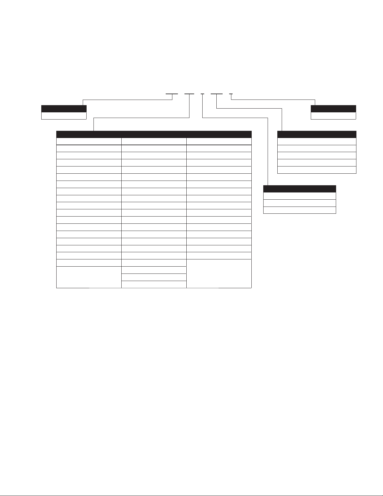
Chapter 1—Variable Speed Drives Series III overview
Catalog number system
Figure 4. Johnson Controls Series III VSD—catalog numbering system
VS3 – 010 – 4 – UL1 – 0
Basic Naming
VS3 = Drive
VS3 hp Rating
208–240 V 380–500 V 525–600 V
001 = 1.0 hp, 4.8 A, 0.75 kW 1D5 = 1.5 hp, 3.3 A, 1.1 kW 003 = 3 hp, 4.5 A, 2.2 kW
1D5 = 1.5 hp, 6.6 A, 1.1 kW 002 = 2.0 hp, 4.3 A, 1.5 kW 005 = 5.0 hp, 7.5 A, 3.7 kW
002 = 2.0 hp, 7.8 A, 1.5 kW 003 = 3.0 hp, 5.6, 2.2 kW 7D5 = 7.5 hp, 10 A, 5.5 kW
003 = 3.0 hp, 11 A, 2.2 kW 004 = 4.0 hp, 7.6 A, 3 kW 010 = 10 hp, 13.5 A, 7.5 kW
004 = 4 hp, 12.5 A, 3.0 kW 005 = 5 hp, 9 A, 4 kW 015 = 15 hp, 18 A, 11 kW
005 = 5.0 hp, 17.5 A, 3.7 kW 7D5 = 7.5 hp, 12 A, 5.5 kW 020 = 20 hp, 22 A, 15 kW
7D5 = 7.5 hp, 25 A, 5.5 kW 010 = 10 hp, 16 A, 7.5 kW 025 = 25 hp, 27 A, 18.5 kW
010 = 10 hp, 31 A, 7.5 kW 015 = 15 hp, 23 A, 11 kW 030 = 30 hp, 34 A, 22 kW
015 = 15 hp, 48 A, 11 kW 020 = 20 hp, 31 A, 15 kW 040 = 40 hp, 41 A, 30 kW
020 = 20 hp, 61 A, 15 kW 025 = 25 hp, 38 A, 18.5 kW 050 = 50 hp, 52 A, 37 kW
025 = 25 hp, 75 A, 18.5 kW 030 = 30 hp, 46 A, 22 kW 060 = 60 hp, 62 A, 45 kW
030 = 30 hp, 88 A, 22 kW 040 = 40 hp, 61 A, 30 kW 075 = 75 hp, 80 A, 55 kW
040 = 40 hp, 114A , 30 kW 050 = 50 hp, 72 A, 37 kW 100 = 100 hp, 100 A, 75 kW
050 = 50 hp, 143 A, 37 kW 060 = 60 hp, 87 A, 45 kW 125 = 125 hp, 125 A, 90 kW
060 = 60 hp, 170 A, 45 kW 075 = 75 hp, 105 A, 55 kW 150 = 150 hp, 144 A, 110 kW
075 = 75 hp, 211 A, 55 kW 100 = 100 hp, 140 A, 75 kW 200 = 200 hp, 208 A, 132 kW
100 = 100 hp, 261 A, 75 kW 125 = 125 hp, 170 A, 90 kW 250 = 250 hp, 250 A, 160 kW
125 = 125 hp, 312 A, 90 kW 150 = 150 hp, 205 A, 110 kW
200 = 200 hp, 261 A, 132 kW
250 = 250 hp, 310 A, 160 kW
Bypass Option
0 = N/A
Style
UL1 = Open Drive UL Type 1
UL2 = Open Drive UL Type 12
EP0 = Open Drive IP20 with EMC Filter
EP1 = Open Drive IP21 with EMC Filter
EP2 = Open Drive IP54 with EMC Filter
Input / Output Voltage
2 = 230 V (208–240 V, –15%, +10%)
4 = 400 V (380–500 V, –15%, +10%)
5 = 600 V (525–600 V, –15%, +10%)
VARIABLE SPEED DRIVE SERIES III LIT-12012999—June 2018 www.johnsoncontrols.com
3
Page 28

Chapter 1—Variable Speed Drives Series III overview
Power ratings and product selection
VS3 drives—FRO, 230 Volt
Table 2. Open Type /IP20
Constant torque (CT)/high overload (IH) Variable torque (VT)/low overload (IL)
Frame size
230 V, 50 Hz
kW rating
FR0 0.55 0.75 3.7 0.75 1 4.8 VS3-324D8EB-C20C
0.75 1 4.8 1.1 1.5 6.6 VS3-326D6EB-C20C
1.1 1.5 6.6 1.5 2 7.8 VS3-327D8EB-C20C
Note: IP20 FR0 will be available in June 2019.
VS3 drives—FR1 - FR6, 230 Volt
Table 3. Type 1/IP21
Constant torque (CT)/high overload (IH) Variable torque (VT)/low overload (IL)
Frame size
FR1 0.55 0.75 3.7 0.75 1 4.8 VS3-324D8DN-C21C
FR2 3 – 12.5 3.7 5 17.5 VS3-32017DN-C21C
FR3 7.5 10 31 11 15 48 VS3-32048DN-C21C
FR4 15 20 61 18.5 25 75 VS3-32075DN-C21C
FR5 30 40 114 37 50 143 VS3-32143DN-C21C
FR6 55 75 211 75 100 261 VS3-32261DN-C21C
230 V, 50 Hz
kW rating
0.75 1 4.8 1.1 1.5 6.6 VS3-326D6DN-C21C
1.1 1.5 6.6 1.5 2 7.8 VS3-327D8DN-C21C
1.5 2 7.8 2 .2 3 11 VS3-32011DN-C21C
2.2 3 11 3 – 12.5 VS3-32012DN-C21C
3.7 5 17.5 5.5 7.5 25 VS3-32025DN-C21C
5.5 7.5 25 7.5 10 31 VS3-32031DN-C21C
11 15 4 8 15 2 0 61 VS3-32061DN-C21C
18.5 25 75 22 30 88 VS3-32088DN-C21C
22 30 88 30 40 114 VS3-32114DN-C21C
37 50 143 45 60 170 VS3-32170DN-C21C
45 60 170 55 75 211 VS3-32211DN-C21C
75 100 248 90 125 312 VS3-32312DN-C21C
230 V, 60 Hz hpCurrent
230 V, 60 Hz hpCurrent
A
A
230 V, 50 Hz
kW rating
230 V, 50 Hz
kW rating
230 V, 60 HzhpCurrent
230 V, 60 HzhpCurrent
A
A
VS3
Catalog number
VS3
Catalog number
Table 4. Type 12/IP54
Constant torque (CT)/high overload (IH) Variable torque (VT)/low overload (IL)
Frame size
230 V, 50 Hz
kW rating
FR1 0.55 0.75 3.7 0.75 1 4.8 VS3-324D8DN-C54C
0.75 1 4.8 1.1 1.5 6.6 VS3-326D6DN-C54C
1.1 1.5 6.6 1.5 2 7.8 VS3-327D8DN-C54C
1.5 2 7.8 2 .2 3 11 VS3-32011DN-C54C
2.2 3 11 3 – 12.5 VS3-32012DN-C54C
FR2 3 – 12.5 3.7 5 17.5 VS3-32017DN-C54C
3.7 5 17.5 5.5 7.5 25 VS3-32025DN-C54C
5.5 7.5 25 7.5 10 31 VS3-32031DN-C54C
FR3 7.5 10 31 11 15 48 VS3-32048DN-C54C
11 15 4 8 15 2 0 61 VS3-32061DN-C54C
FR4 15 20 61 18.5 25 75 VS3-32075DN-C54C
18.5 25 75 22 30 88 VS3-32088DN-C54C
22 30 88 30 40 114 VS3-32114DN-C54C
4
VARIABLE SPEED DRIVE SERIES III LIT-12012999—June 2018 www.johnsoncontrols.com
230 V, 60 Hz hpCurrent
A
230 V, 50 Hz
kW rating
230 V, 60 HzhpCurrent
A
VS3
Catalog number
Page 29

Chapter 1—Variable Speed Drives Series III overview
Table 4. Type 12/IP54, continued
Constant torque (CT)/high overload (IH) Variable torque (VT)/low overload (IL)
Frame size
230 V, 50 Hz
kW rating
FR5 30 40 114 37 50 143 VS3-32143DN-C54C
37 50 143 45 60 170 VS3-32170DN-C54C
45 60 170 55 75 211 VS3-32211DN-C54C
FR6 55 75 211 75 100 261 VS3-32261DN-C54C
75 100 248 90 125 312 VS3-32312DN-C54C
VS3 drives—FRO, 380-500 Volt
Table 5. Open Type /IP20
Constant torque (CT)/high overload (IH) Variable torque (VT)/low overload (IL)
Frame size
FR0 0.75 1 2.2 1.1 1.5 3.3 VS3-343D3EB-C20C
400 V, 50 Hz
kW rating
1.1 1.5 3.3 1.5 2 4.3 VS3-344D3EB-C20C
1.5 2 4.3 2 .2 3 5 .6 VS3-345D6EB-C20C
2.235.6357.6VS3-347D6EB-C20C
230 V, 60 Hz hpCurrent
460 V, 60 Hz hpCurrent
A
A
230 V, 50 Hz
kW rating
400 V, 50 Hz
kW rating
230 V, 60 HzhpCurrent
460 V, 60 HzhpCurrent
A
A
VS3
Catalog number
VS3
Catalog number
Note: IP20 FR0 will be available in June 2019.
VS3 series drives—380–500 volt
Table 6. Type 1/IP21
Constant torque (CT)/high overload (IH) Variable torque (VT)/low overload (IL)
Frame size
400 V, 50 Hz
kW rating
FR1 0.75 1 2.2 1.1 1.5 3.3 VS3-343D3DN-C21C
1.1 1.5 3.3 1.5 2 4.3 VS3-344D3DN-C21C
1.5 2 4.3 2 .2 3 5 .6 VS3-345D6DN-C21C
2.235.6357.6VS3-347D6DN-C21C
357.64–9 VS3-349D0DN-C21C
4–9 5.57.512 VS3-34012DN-C21C
FR2 5.5 7.5 12 7.5 10 16 VS3-34016DN-C21C
7.5 10 1 6 1 1 15 2 3 VS3-34023DN-C21C
11 15 2 3 15 2 0 31 VS3-34031DN-C21C
FR3 15 20 31 18.5 25 38 VS3-34038DN-C21C
18.5 25 38 22 30 46 VS3-34046DN-C21C
22 30 46 30 40 61 VS3-34061DN-C21C
FR4 30 40 61 37 50 72 VS3-34072DN-C21C
37 50 72 45 60 87 VS3-34087DN-C21C
45 60 87 55 75 105 VS3-34105DN-C21C
FR5 55 75 105 75 100 140 VS3-34140DN-C21C
75 100 140 90 125 170 VS3-34170DN-C21C
90 125 170 110 150 205 VS3-34205DN-C21C
FR6 110 150 205 132 200 261 VS3-34261DN-C21C
150 2 00 24 5 160 250 310 VS3-34310DN-C21C
460 V, 60 Hz hpCurrent
A
400 V, 50 Hz
kW rating
460 V, 60 HzhpCurrent
A
VS3
Catalog number
VARIABLE SPEED DRIVE SERIES III LIT-12012999—June 2018 www.johnsoncontrols.com
5
Page 30

Chapter 1—Variable Speed Drives Series III overview
Table 7. Type 12/IP54
Constant torque (CT)/high overload (IH) Variable torque (VT)/low overload (IL)
Frame size
400 V, 50 Hz
kW rating
FR1 0.75 1 2.2 1.1 1.5 3.3 VS3-343D3DN-C54C
1.1 1.5 3.3 1.5 2 4.3 VS3-344D3DN-C54C
1.5 2 4.3 2 .2 3 5 .6 VS3-345D6DN-C54C
2.235.6357.6VS3-347D6DN-C54C
357.6 4–9 VS3-349D0DN-C54C
4–9 5.57.512 VS3-34012DN-C54C
FR2 5.5 7.5 12 7.5 10 16 VS3-34016DN-C54C
7.5 10 1 6 1 1 15 2 3 VS3-34023DN-C54C
11 15 2 3 15 2 0 31 VS3-34031DN-C54C
FR3 15 20 31 18.5 25 38 VS3-34038DN-C54C
18.5 25 38 22 30 46 VS3-34046DN-C54C
22 30 46 30 40 61 VS3-34061DN-C54C
FR4 30 40 61 37 50 72 VS3-34072DN-C54C
37 50 72 45 60 87 VS3-34087DN-C54C
45 60 87 55 75 105 VS3-34105DN-C54C
FR5 55 75 105 75 100 140 VS3-34140DN-C54C
75 100 140 90 125 170 VS3-34170DN-C54C
90 125 170 110 150 205 VS3-34205DN-C54C
FR6 110 150 205 132 200 261 VS3-34261DN-C54C
150 2 00 24 5 160 250 310 VS3-34310DN-C54C
460 V, 60 Hz hpCurrent
A
400 V, 50 Hz
kW rating
460 V, 60 HzhpCurrent
A
VS3
Catalog number
VS3 drives—600 volt
Table 8. Type 1/IP21
Constant torque (CT)/high overload (IH) Variable torque (VT)/low overload (IL)
Frame size
600 V, 60 Hz
kW rating
FR1 1.5 2 3.3 2.2 3 4.5 VS3-354D5DN-C21C
2.2 3 4.5 3.7 5 7.5 VS3-357D5DN-C21C
3. 7 5 7. 5 5 .5 7. 5 1 0 VS3-35010DN-C21C
FR2 5.5 7.5 10 7.5 10 13.5 VS3-35013DN-C21C
7.5 10 1 3. 5 11 1 5 1 8 VS3-35018DN-C21C
11 15 18 15 20 22 VS3-35022DN-C21C
FR3 15 20 22 18.5 25 27 VS3-35027DN-C21C
18.5 25 27 22 30 34 VS3-35034DN-C21C
22 30 34 30 40 41 VS3-35041DN-C21C
FR4 30 40 41 37 50 52 VS3-35052DN-C21C
37 50 52 45 60 62 VS3-35062DN-C21C
45 60 62 55 75 80 VS3-35080DN-C21C
FR5 557580 75100100 VS3-35100DN-C21C
75 100 100 90 125 125 VS3-35125DN-C21C
90 125 125 110 150 144 VS3-35144DN-C21C
FR 6 110 150 144 15 0 200 20 8 VS3-35208DN-C21C
150 2 00 208 187 250 2 50 VS3-35250DN-C21C
600 V, 60 Hz hpCurrent
A
600 V, 60 Hz
kW rating
600 V, 60 HzhpCurrent
A
VS3
Catalog number
6
VARIABLE SPEED DRIVE SERIES III LIT-12012999—June 2018 www.johnsoncontrols.com
Page 31

Chapter 1—Variable Speed Drives Series III overview
Table 9. Type 12/IP54
Constant torque (CT)/high overload (IH) Variable torque (VT)/low overload (IL)
Frame size
600 V, 60 Hz
kW rating
FR1 1.5 2 3.3 2.2 3 4.5 VS3-354D5DN-C54C
2.2 3 4.5 3.7 5 7.5 VS3-357D5DN-C54C
3. 7 5 7. 5 5 .5 7. 5 1 0 VS3-35010DN-C54C
FR2 5.5 7.5 10 7.5 10 13.5 VS3-35013DN-C54C
7.5 10 1 3. 5 11 1 5 1 8 VS3-35018DN-C54C
11 15 18 15 20 22 VS3-35022DN-C54C
FR3 15 20 22 18.5 25 27 VS3-35027DN-C54C
18.5 25 27 22 30 34 VS3-35034DN-C54C
22 30 34 30 40 41 VS3-35041DN-C54C
FR4 30 40 41 37 50 52 VS3-35052DN-C54C
37 50 52 45 60 62 VS3-35062DN-C54C
45 60 62 55 75 80 VS3-35080DN-C54C
FR5 557580 75100100 VS3-35100DN-C54C
75 100 100 90 125 125 VS3-35125DN-C54C
90 125 125 110 150 144 VS3-35144DN-C54C
FR 6 110 150 144 15 0 200 20 8 VS3-35208DN-C54C
150 2 00 208 187 250 2 50 VS3-35250DN-C54C
600 V, 60 Hz hpCurrent
A
600 V, 60 Hz
kW rating
600 V, 60 HzhpCurrent
A
VS3
Catalog number
VARIABLE SPEED DRIVE SERIES III LIT-12012999—June 2018 www.johnsoncontrols.com
7
Page 32

Chapter 2—Keypad overview
Chapter 2—Keypad overview
The keypad is the interface between the drive and the user. It features an LCD display, 3 LED lights
and 11 buttons. With the control keypad, it is possible to control the speed of a motor, to supervise
the state of the equipment and to set the frequency converter’s parameters. See Figure 5.
Figure 6. Keypad and display
Programmable Soft Key 1
Increase Value
Scroll Menu Up
Back/Reset Button
Stop/Off Button
Move Cursor Left
Enter Menu
Confirm Selection
Programmable Soft Key 2
Auto Control Place Select
Move Cursor Right
Start /Hand Button
Decrease Value
Scroll Menu Down
8 VARIABLE SPEED DRIVE SERIES III LIT-12012999—June 2018 www.johnsoncontrols.com
Page 33

Keypad buttons
Chapter 2—Keypad overview
Buttons description
Table 10. Keypad buttons
Icon Button Description
Soft key 1,
Soft key 2
Back/Reset
Auto
Soft key 1, soft key 2:
The functions of these two buttons shall be the following:
•
Forward/Reverse, this shall change motor’s run direction.
•
Menu, this shall return to main menu.
•
Details, this shall display the details of the fault.
•
Bypass, this shall make drive go into bypass.
•
Jog, this shall activate jog. Jog can enabled via press OK Key and Soft2 Key(When the
Soft2Key is Jog) and disabled via release any one of the two keys.
•
Favorite, this shall add this parameter to the Favorite menu.
•
Delete, this shall delete this parameter from the Favorite menu.
Back/Reset:
This button has three integrated functions. The button operates as backward button
during normal mode. In edit mode, it is used as cancel operate. It is also used to reset
faults when faults occur.
•
Backs up one step.
•
Cancels Modify in edit mode.
•
Resets the active faults (all the active faults shall be reset by pressing this button more
than 2 seconds in any page).
•
Hold Stop and Back Reset for 5 seconds to return drive to factory default
•
At Main Menu page by hitting Back/Reset takes to Default Page.
Auto:
This button switches the drive into the auto control place.
Up
Down
Up and down arrows:
•
Move either up or down a menu list to select the desired menu item.
•
Editing a parameter bit by bit, while the active digit is scrolled.
•
Increase/decrease the reference value of the selected parameter.
•
In parameter comparison mode, scroll through the parameters of which current value is
different from comparison parameter value.
•
In parameter page when in read mode, move to the previous or next brother parameter of
this parameter.
9VARIABLE SPEED DRIVE SERIES III LIT-12012999—June 2018 www.johnsoncontrols.com
Page 34

Chapter 2—Keypad overview
Table 10. Keypad buttons, continued
Icon Button Description
Left
Left arrow:
•
Navigation button, movement to left when editing a parameter digit by digit.
•
Backs up one step.
•
At Main Menu page by hitting Back/Reset takes to Default Page.
Right
OK
Stop
Start
Right arrow:
•
Enter parameter group mode.
•
Enter parameter mode from group mode.
•
Enter parameter whole edit mode when this parameter can be written.
•
Enter parameter bit by bit edit mode from whole edit mode.
•
Navigation button, movement to right when editing a parameter bit by bit.
OK:
•
Will clear all the fault history if pressed for more than 5 seconds (including 5seconds) in
any page.
•
This button is used in the parameter edit mode to save the parameter setting.
•
To confirm the start-up list at the end of the Start-Up Wizard.
•
To confirm the comparison item in parameters comparison mode.
The following is the same with Right key:
•
Enter parameter whole edit mode when this parameter can be written.
•
Enter parameter group mode.
•
Enter parameter mode from group mode.
Stop/Off:
This button operates as the motor stop button for normal operation and places the drive
in the off control location. The default is for thisbutton to always be active. It can be
changed in parameter P4.1.3 to only when “Keypad” is selected as the control source.
•
Motor stop from the keypad.
•
Transitions drive into a Off control location preventing start from any control source.
Start/Hand:
This button operates as motor start button for normal operation when the “Keypad” is
selected as the active control source, as well as selects the Hand control place location.
When Keypad is the reference place after hitting the start button, it will jump directly
tothe Keypad Ref Screen. Places drive into Hand Control place. Hitting start again if
keypad is the control location will start the Drive.
10 VARIABLE SPEED DRIVE SERIES III LIT-12012999—June 2018 www.johnsoncontrols.com
Page 35

Chapter 2—Keypad overview
LED lights
Table 11. LED state indicators
Indicator Description
Run:
Indicates that the VFD is running and controlling the load in Drive
Run
Fault
Auto
or Bypass.
Blinks when a stop command has been given but the drive is still
ramping down.
Fault:
Turn on when there is one or more active drive fault(s).
Auto:
Hand/Off: If the Hand or Off control place is selected, the light
will be off.
Auto: If the Auto control place is selected, the light will be on.
LCD display
The keypad LCD indicates the status of the motor and the
drive and any faults in motor or drive functions. On the LCD,
the user sees information about the current location in the
menu structure and the item displayed.
Overview
Five lines shall be displayed in the screen. General view is
as following in Figure 5.
Figure 7. General view of LCD
Active
Selection
Drive Status
Direction Status
Control Place
Menu Location
The lines definition is as below:
The first line is State line, shows:
•
RUN/STP/NRD/FIM/TFM—If motor is running, the run
state shall display “RUN”, otherwise the state display
“STP”. “RUN” blinks when the stop command is sent but
the drive is decelerating. “NRD” is displayed if the drive
is not ready or does not have a signal “FIM” is displayed
to indicate it is in Fire Mode and the drive is in a Run
state. “TFM” is displayed when in the Fire Mode Test
Mode and the drive is in a Run State.
•
FWD/REV/JOG—If the motor running direction is
clockwise, display “FWD”, otherwise display “REV” “Jog”
if the drive is in Jog mode the status indication will occur.
•
KEY/I/O/BPS/RBP/BUS/OFF—If it is in bypass
currently, display “BPS”; when run command is given it
will got to “RBP”. otherwise, if the current control source
is I/O terminal, display “I/O”. If it is keypad, then display
“KEY”; otherwise display “BUS.” When indicates “OFF”
it indicates the drive will not accept a command from the
Hand or Auto Control place.
•
PAR/MON/FLT/OPE/QSW/FAV/TPM/BUx.—If the
current page is parameter menu, display “PAR”; If
monitor menu, then display “MON”; If fault menu, then
display “FLT”; If operation menu, then display “OPE”;
If quick start wizard, then display “QSW”; If optional
card menu, then display “BOA”; If favorite menu, then
display “FAV”; If main menu, then display “TPM”.
“BUx” indicates the drive being a backup drive when in
the redundant drive system.
The second line is Code line, shows the menu code.
The third line is Name line, shows the menu name or
parameters name.
The fourth line is Value line, shows the submenu name or
parameters value.
The fifth line is Soft key line, the functions of Soft key 1 and
Soft key 2 are changeable, and the real time is in the middle.
Welcome page
LCD shall show the welcome page when power on.
See Figure 6.
Soft Key 1
Function Label
Real Time Clock
(hh:mm)
Figure 8. Welcome page
Soft Key 2
Function Label
11VARIABLE SPEED DRIVE SERIES III LIT-12012999—June 2018 www.johnsoncontrols.com
Page 36

Chapter 2—Keypad overview
Upgrade page
After welcome page, keypad will check whether there is
different keypad firmware version in MCU’s serial flash. If
yes, then ask user whether to upgrade the keypad.
Figure 9. Upgrade page
STP FWD KEY QSW
Current Version: 1.01.0003
To Upgrade Version: 1.01.0004
To Upgrade? Press OK or BACK
13:53
Auto backup page
If keypad is plugged into a new drive, then auto backup
page will be shown to notice the user whether to do the
upload/download.
Figure 10. Auto backup page
STP FWD KEY MON
Download from keypad
No Action
Upload to keypad
Soft key description
There are two soft key buttons. They have different
definitions under different pages.
Table 12. Soft keys
Bypass Enabled
Keypad Display Softkey 1 Softkey 2
Main menu page Bypass Jog
Group node page
Parameter node page
favorite page
fault page
Monitor Page
Bypass Disabled
Keypad Display Softkey 1 Softkey 2
Main menu page
Group node page REVERSE/FORWARD Menu
Parameter node page Null/Favorite Menu
favorite page Delete Menu
fault page REVERSE/FORWARD Menu
Monitor Page REVERSE/FORWARD Menu
*Note: if Para ID2412 or Para ID2413 is set to hidden it
will hide this value.
1. In the main menu (root node), “JOG” shall be shown
on the right. If bypass is enabled, then “BYPASS” shall
be shown on the left. Otherwise, it will not be shown.
SeeFigure 10
Figure 11. Main menu
Bypass REVERSE/FORWARD
Bypass Null/Favorite
Bypass Delete
Bypass
Bypass
Null Jog
REVERSE/FORWARD
REVERSE/FORWARD
13:53
STP FWD KEY TPM
S: Startup Wizard
M: Monitor
P: Parameter
12 VARIABLE SPEED DRIVE SERIES III LIT-12012999—June 2018 www.johnsoncontrols.com
13:53BYPASS
JOG
Page 37

Chapter 2—Keypad overview
2. For the parameter group, the two soft keys
“REVERSE/FORWARD” and “BYPASS” shall be shown.
See Figure 11
Figure 12. Parent node page
STP FWD KEY PAR
P1: Basic Parameters
P2: Inputs
P3: Outputs
13:53BYPASS
3. For the parameter menu, if this parameter hasn’t been
added into the favorite list, two soft keys “FAVORITE”
and “BYPASS” shall be shown. If it has been added
into the favorite list, only one soft key “BYPASS” is
shown in the right.
Figure 13. Parameter page
STP FWD KEY PAR
REVERSE
4. If one parameter has been added to the favorite list, it
shall appear in the favorite menu. Then when you enter
into the favorite menu, two soft keys “DELETE” and
“BYPASS” shall be shown, and “DELETE” means you
can delete the selected parameter from favorite list.
See Figure 13
Figure 14. Parameter page from favorite menu
STP FWD KEY FLT
P2.5.1: AI2 Mode
M1.2: Reference Frequency
M1.3: Motor Speed
BYPASS
5. For the fault group, two soft keys “DETAILS” and
“BYPASS” shall be shown. See Figure 14. For more
information, see Page 16
Figure 15. Fault page
13:53
STP FWD KEY FLT
P2.5.1
AI2 Mode
0 - 20mA
BYPASS
13:53
FAVORITE
F1.1: Fault
Over Voltage
04.08.12 13:53:45
BYPASS
13:53
DETAILS
13VARIABLE SPEED DRIVE SERIES III LIT-12012999—June 2018 www.johnsoncontrols.com
Page 38

Chapter 3—Menu overview
Chapter 3—Menu overview
Main menu page
The data on the keypad are arranged in menus and
sub-menus. The first menu level consists of M, P, F, B, T,
Oand S, and it is called the Main Menu.
Figure 16. Main menu page
STP FWD KEY TPM
S: Startup Wizard
M: Monitor
P: Parameter
13:53BYPASS
JOG
Menu navigation
This section provides basic instruction on navigating each section in the menu structure.
Figure 17. Main menu navigation
Back/left key Right/OK key
M1 – Basic
...
M10 – Multi-Monitoring
M1.1
Output Frequency
0.00 Hz
P1.1 – Min Frequency
UP key
Down key
M - Monitor
P - Parameters
... ...
F - Fault
B – Optional Boards
T- Favorite
P13 - System
F1 – Active Fault
F2 – History Fault
F3 – Fault Log
P1.16 – Auto 2 Reference
P1.1P1 – Basic Parameters
Min Frequency
0.00 Hz
O – Operate Mode
S – Startup Wizard
14 VARIABLE SPEED DRIVE SERIES III LIT-12012999—June 2018 www.johnsoncontrols.com
Page 39

Menu structure
Table 13. Keypad menus
Item Description Item Description
Monitor M1 - Basic Fault F1 - Active Fault
M2 - IO Status F2 - History fault
M3 - Optional Boards F3 - Fault Log
M4 - Energy savings Option Boards B1 - Slot A
M5 - FB Monitor Menu B2 - Slot B
M6 - PID Monitor Favorite
M7 - Timer/Interval Control Operate Menu O1 - Output Frequency
M8- User Defined Output O2 - Freq Reference
M9 - MWH Monitor O3 - Motor Speed
M10 - Multi-Monitoring O4 - Motor Current
Parameter P1 - Basic Parameter O5 - Motor Torque
P2 - Inputs O6 - Motor Power
P3 - Outputs O7 - Motor Voltage
P4 - Drive Control O8 - DC-link Voltage
P5 - Motor Control O9 - Unit Temperature
P6 - Protections O10 - Motor Temperature
P7 - PID Controller 1 R11 - Keypad Reference
P8 - PID Controller 2 R12 - PID1 Keypad Set Point 1
P9 - Fire Mode R13 - PID1 Keypad Set Point 2
P10 - Bypass Startup Wizard S - Startup Wizard
P11 - Real Time Clock
P12 - Communictions
P13 - System
Chapter 3—Menu overview
ote: N Will vary depending on application selected
15VARIABLE SPEED DRIVE SERIES III LIT-12012999—June 2018 www.johnsoncontrols.com
Page 40

Chapter 3—Menu overview
M — Monitor
In monitor page, user shall not be able to edit the parameters except multi-monitor parameter. Multi-monitor parameters
allowfor displaying 3 monitor values on display. The three values can be changed to any of the listed values.
The navigation for monitor is as Figure 17.
Figure 18. M—Monitor
STP FWD KEY TPM
S - Startup Wizard
M - Monitor
P - Parameter
BYPASS JOG
13:53
STP FWD KEY MON
M9 – MWH Monitor –
M10: Multi-Monitoring
M1: Basic
BYPASS REVERSE13:53
Right / OK key twice
STP FWD KEY MON
Output Frequency –
0.00 Hz
Freq Reference – 0.00Hz
Motor Speed - 0
BYPASS REVERSE13:53
Right / OK key
Down Key 10 times
Right key
STP FWD KEY MON
M10: Multi-Monitoring
M1 – Basic
M2 – IO Status
BYPASS REVERSE
13:53
Right / OK key
STP FWD KEY MON
M1.13: RTC Battery Status–
M1.1: Output Frequency
M1.2: Freq Reference
BYPASS REVERSE13:53
STP FWD KEY MON
Output Frequency 0.00 Hz
M1.2 - Freq Reference
Motor Speed – 0 rpm
BYPASS REVERSE13:53
UP key
Down key
twice
STP FWD KEY MON
M9: MWH Monitor
M10 – Multi-Monitoring
M1: Basic
BYPASS REVERSE
Down key
13:53
STP FWD KEY MON
M1.1: Output Frequency–
M1.2: Freq Reference
M1.3: Motor Speed
BYPASS REVERSE13:53
STP FWD KEY MON
Output Frequency – 45Hz
M1.4 - Motor Current
Motor Speed – 0 rpm
BYPASS REVERSE
13:53
Ok key
STP FWD KEY MON
Output Frequency – 45Hz
Motor Current – 0.0A
Motor Speed – 0 rpm
BYPASS REVERSE
13:53
16 VARIABLE SPEED DRIVE SERIES III LIT-12012999—June 2018 www.johnsoncontrols.com
Page 41

Chapter 3—Menu overview
F — Fault
There are three fault pages. The first one is F1 active faults;
the second one will pop-up automatically when fault occurs;
the third one is F2 fault history.
If there is no active fault/history fault, then “No fault” shall
be shown.
Active fault
The navigation for active faults is as Figure 18.
Figure 19. Active faults
STP FWD KEY TPM
P: Parameters–
F: Fault
B: Optional Boards
BYPASS JOG13:53
STP FWD KEY FLT
F1.3: Over Current–
F1.1: Over Voltage
F1.2: System Fault
BYPASS REVERSE13:53
Right / OK key
STP FWD KEY FLT
F3: Fault Log
F1: Active Fault
F2: History Fault
BYPASS REVERSE13:53
Has Active Faults
Right/OK key
After the DETAIL soft key is pressed, the following detail
information about the fault shall be shown: fault code,
type, power day count, power hour count, frequency,
current, voltage, power, torque, DC voltage, unit
temperature, run status, direction, warning, zero speed,
Mwh count, at reference.
Right/OK Key
STP FWD KEY FLT
F1.1: Fault–
Over Voltage
04:08:12 13:53:45
BYPASS DETAILS13:53
STP FWD KEY FLT
F3: Fault Log–
F1: Active Fault
F2: History Fault
BYPASS REVERSE13:53
Soft Key 2
Right/OK Key
No Active Fault
STP FWD KEY FLT
Code: 2
Type: Fault
Operation Days: 0
MENU13:53
Down Key
STP FWD KEY FLT
Type: Fault
Operation Days: 0
Operation hours: 13
MENU13:53
STP FWD KEY FLT
No Fault
BYPASS
13:53
REVERSE
17VARIABLE SPEED DRIVE SERIES III LIT-12012999—June 2018 www.johnsoncontrols.com
Page 42

Chapter 3—Menu overview
Pop-up fault
The navigation for the pop-up active fault is as Figure 19.
Figure 20. Pop-up active faults
Back key to the
last page
STP FWD KEY FLT
F1.2: Fault
Over Voltage
Soft key 2
2012.04.08 12:30:45
BYPASS
The latest active fault page shall pop up when there is
a new active fault, the pop-up fault page is the same as the
active fault page.
Pressing the back/reset key less than 2 seconds shall back
to the last page user is watching.
Pressing the back/reset key more than 2 seconds shall
reset all active faults when all the active fault condition
is not satisfied.
13:53
DETAILS
STP
FWD KEY FLT
Code: 2
Type: Fault
Total Power Day Count: 0
MENU13:53
User shall be able to navigate all the active faults by
up/down key.
The page for active faults and pop-up faults are the same,
except one: the response to the “Back” key. In active faults
page, if the Back key is pressed, it returns to the last level
menu. In pop-up faults page, it returns to the last page.
18 VARIABLE SPEED DRIVE SERIES III LIT-12012999—June 2018 www.johnsoncontrols.com
Page 43

Fault history
The navigation for fault history is as Figure 20.
In any page, OK button is used to clear all the
active faults and fault history by pressing more than
5s without password.
Figure 21. Fault history
Chapter 3—Menu overview
STP FWD KEY TPM
P: Parameters
F: Fault
B: Optional Boards
BYPASS
13:53
STP FWD KEY FLT
F2.10: Over Current
F2.1: Over Voltage
F2.2: System Fault
BYPASS REVERSE13:53
Right/OK
Key
STP FWD KEY FLT
F2.1: Fault
Over Voltage
04.08.12 13;53;45
BYPASS
13:53
DETAILS
JOG
Right/OK ke
Soft Key 2
STP FWD KEY FLT
F1: Active Fault
F2: HistoryFault
F3: Fault Log
BYPASS REVERSE13:53
Has Active Faults
Right/OK Key
STP FWD KEY FLT
Code: 2
Type: Faul
t
Operation Days: 0
Down key
MENU13:53
STP FWD KEY
F1: Active Fault
F2: HistoryFault
F3: Fault Log
BYPASS
13:53
FLT
REVERSE
Right/OK key
No Active Fault
STP FWD KEY FLT
Type: Fault
Total Power Day Count: 0
Operation Hours: 13
STP
FWD KEY FLT
No Fault
BYPASS
13:53
REVERSE
MENU13:53
19VARIABLE SPEED DRIVE SERIES III LIT-12012999—June 2018 www.johnsoncontrols.com
Page 44

Chapter 3—Menu overview
Fault Log
The Fault Log will store the last 50 faults in it with 1 being
the most recent and 50 being the oldest. Only the fault
code, name and time stamp are stored with these faults.
P — Parameter
The navigation for the parameter menu is shown
in
Figure 21.
In parameter page, the parameter code shall be shown in
the second line (such as P1.1).
In parameter page, the parameter name shall be shown in
the third line (such as Min Frequency).
Figure 22. Parameter setting
STP FWD KEY PAR
P1.1
Min Frequency
0.00 Hz
13:53
Up/down key to
STP FWD KEY PAR
P1.1
Min Frequency
0.10 Hz
BYPASS
STP FWD KEY PAR
P1.1
Min Frequency
0.10 Hz
BYPASS
edit during 0 - 9
13:53
Ok key to
confirm
13:53
FAVORITE
FAVORITE
Left key to
move the
edit bit
STP FWD KEY PAR
P1.1
Min Frequency
0.00 Hz
FAVORITEFAVORITE
BYPASSBYPASS
13:53
In parameter page, the value of parameter and unit shall be
shown in the fourth line (0.00 Hz).
If the parameter is read and write, then pressing the right
key shall make the parameter value flash, which means that
the value can be edited.
If the parameter is read only, then pressing the right
key will not have any effect, which means that the value
can’t be edited.
Right key to
edit by digital
STP FWD KEY TPM
M: Monitor
P: Parameter
F: Fault
BYPASS JOG13:53
STP FWD KEY PAR
P1.1
Min Frequency
0.00 Hz
Up key
13:53
Ok key
13:53
FAVORITE
FAVORITE
FAVORITE
BYPASS 13:53
STP FWD KEY PAR
P1.1
Min Frequency
0.01 Hz
BYPASS
STP FWD KEY PAR
P1.1
Min Frequency
0.01 Hz
BYPASS
STP FWD KEY PAR
P13: System
Right/OK key
P1: Bas ic Param eters
P2: Input
BYPASS REVERS E13:53
STP FWD KEY PAR
P1.16 - Auto 2 Reference
Right key
two times
P1.1:Min Frequency
P1.2: Max Frequency
BYPASS REVERSE
13:53
Right/OK
key
There are several special pages:
•
1. P 13.1.3 Parameter Sets. See Figure 22.
User shall be able to load or store parameters. The options
are as follows: Reload Defaults, Reload Set 1, Reload Set
2, Store Set 1, Store Set 2, Reset, Reload Defaults VM. The
special points are:
During this operation, “waiting…” shall flash, which
means it is in process
•
When it is finished, “OK” shall be shown
•
Drive shall restart after default parameters are loaded
•
“Reload Defaults VM” is for the sales stand. Do not use
on a fully functioning drive
20 VARIABLE SPEED DRIVE SERIES III LIT-12012999—June 2018 www.johnsoncontrols.com
Page 45

Figure 23. Parameter sets
STP FWD KEY PAR
P12: Communication
P13: System
P1: Basic Parameters
BYPASS
13:53
Right/OK and
REVERSE
down keys
STP FWD KEY PAR
P13.1.2: Application
P13.1.3: Parameter Sets
P13.1.4: Up to Keypad
Chapter 3—Menu overview
BYPASS
Right key twice
REVERSE13:53
and Up key
STP FWD KEY PAR
P13.1.3
Parameter Sets
Reload defaults
BYPASS
13:53
FAVORITE
Down key
Up key
STP FWD KEY PAR
P13.1.3
Parameter Sets
No
13:53
FAVORITEBYPASS
STP FWD KEY PAR
P13.1.3
Parameter Sets
Reload Set1
13:53
FAVORITEBYPASS
21VARIABLE SPEED DRIVE SERIES III LIT-12012999—June 2018 www.johnsoncontrols.com
Page 46

Chapter 3—Menu overview
2. Up to keypad and P13.1.5 Down from keypad
During this operation, “waiting…” shall flash, which
means it is in process. When it is finished, “OK”
shallbeshown. This stores the parameters to
keypad for transferring.
Figure 24. Down from keypad
STP FWD KEY PAR
P12: Communication
P13: System
P1: Basic Parameters
BYPASS
13:53
and Down Key four times
REVERSE
Right/OK twice
STP FWD KEY PAR
P13.1.4: Up to Keypad
Down key
P13.1.5: Down From Keypad
P13.1.6: Parameter Comparison
BYPASS
13:53
REVERSE
Down from keypad is to download parameters from
keypad to drive. Up to keypad takes the parameters from
the drive and loads them to the keypad.
STP FWD KEY PAR
P13.1.5
Down from Keypad
No
BYPASS
13:53
FAVORITE
Right/OK twice
and Up Key
STP FWD KEY PAR
P13.1.5
Down from Keypad
All Parameters…
BYPASS
13:53
FAVORITE
Ok Key
STP FWD KEY PAR
P13.1.5
Down from Keypad
Waiting...
13:53
Up key
STP FWD KEY PAR
P13.1.5
Down from Keypad
All, No Motor
BYPASS
13:53
FAVORITE
22 VARIABLE SPEED DRIVE SERIES III LIT-12012999—June 2018 www.johnsoncontrols.com
Page 47

Chapter 3—Menu overview
3. P13.1.6 Parameters Comparison
After the operation, the number of different parameter
will be shown. Then press the right key; the first
different parameter shall be shown.
The parameter name shall be shown in the second line,
and the value which is from keypad/default/set1/set2
shall be shown in the third line, the current value shall
be shown in the fourth line.
Figure 25. Parameters comparison
STP FWD KEY PAR
P13.1.5: Down From Keypad
P13.1.6: Parameter Comparison
P13.1.7: Password
BYPASS
STP FWD KEY PAR
P13.1.6
Compare with Keypad
5
13:53
13:53
REVERSE
Right/OK twice
and Up Key
Right Key
Right key
Allows changing
STP FWD KEY PAR
P13.1.6
Parameter Comparison
Compare with Keypad
BYPASS
STP FWD KEY PAR
Fan Control
Continous
Temperature
13:53
13:53
If the user wants to modify the current value, user shall
be able to enter the edit mode by right key.
User shall be able to browse all the different parameters
by up/down key.
During this operation, “waiting…” shall ash, which
means it is in process.
When it is nished, “OK” shall be shown.
See Figure 24.
STP FWD KEY PAR
P13.1.6
OK Key
Parameter Comparison
Waiting...
FAVORITE
Parameter Name
Compared Value
(Keypad, Default, Set1, Set2)
Current Value in Drive
13:53
STP FWD KEY PAR
Fan Control
Continous
Temperature
13:53
Down Key
STP FWD KEY PAR
Backlight Time
2 min
1 min
13:53
Up Key
Down Key
STP FWD KEY PAR
Fan Control
Continous
Continous
13:53
23VARIABLE SPEED DRIVE SERIES III LIT-12012999—June 2018 www.johnsoncontrols.com
Page 48

Chapter 3—Menu overview
4. P13.1.7 Password
Password protects the parameters’ security. Zero means
not used, otherwise in use. If password is in use, user
can still see the values of parameters, but needs to
enter the password before editing. User must enter
current password before changing the password.
0000 shall mean that the password is not used, the
password is 0000 by default.
The password range shall be 0001–9999, the setting of
password and checking of password are as Figure 25.
Figure 26. Password
STP FWD KEY PAR
P13.1.6 - Parameter Comparison
P13.1.7 - Password
P13.1.8 - Parameter Lock
BYPASS REVERSE13:53
STP FWD KEY PAR
P21.1.7
Password
In use
BYPASS BYPASS
13:53
FAVORITE
Right/OK key
OK key
STP FWD KEY PAR
P13.1.7
Password
Not use
BYPASS 13:53
STP FWD KEY PAR
P13.1.7
Password
0001
13:53
FAVORITE
FAVORITE
Enter the password setting page. If the password
is 0000, then the “Not use” shall be shown. If the
password is not 0000, then the “in use” shall be shown.
If the password is in use, and user inputs the wrong
password, then the “failed” shall be shown.
After “failed” is shown 3 seconds, the page shall return
to the parameter read page.
If the password is in use, and user inputs the right
password, then the value shall flash, which indicates
that it can be edited.
STP FWD KEY PAR
Right key
P13.1.7
Password
0000
BYPASS
13:53
FAVORITE
Up key
STP FWD KEY PAR
P2.4.1 - Al 1 Mode
P2.4.2 - Al 1 Signal Range
P2.4.3 - Al 1 Custom Min
BYPASS BYPASS
STP FWD KEY PAR
P2.2.4
AI1 Signal Range
0-100%
BYPASS
13:53
13:53
REVERSE
FAVORITE
After 3s
Right/OK key
STP
OK key
Password righ t
STP FWD KEY PAR
P2.4.2
AI1 Signal Range
0-100%
STP FWD KEY PAR
P2.4.2
Password?
0001
BYPASS
STP FWD KEY PAR
P2.4.2
Password?
Failed
BYPASS
13:53
13:53
OK key Password wrong
13:53
FAVORITE
FAVOIRTE
FAVORITE
Right key
Password in use
STP FWD KEY PAR
P2.4.2
Password?
0000
BYPASS
13:53
FAVORITE
Up key
24 VARIABLE SPEED DRIVE SERIES III LIT-12012999—June 2018 www.johnsoncontrols.com
Page 49

Chapter 3—Menu overview
Value edit
This topic shows the methods to edit value, and what
will happen to edit value when password is in use and
parameter lock is enabled.
We have three methods to edit value: edit by key press-hold,
edit bit by bit, edit click by click.
For details, please see Figure 26. For the editable
parameter, press “Right” key once to enter the read mode
Figure 27. Edit parameter value
STP FWD KEY PAR
P1.1
Min Frequency
0.00Hz
13:53BYPASS FAVORITE
Up key
STP FWD KEY PAR
P1.1
Min Frequency
0.01Hz
13:53BYPASS FAVORITE
Left key
Left key
STP FWD KEY
P1.1
Min Frequency
0.00Hz
STP
P1.1
Min Frequency
0.01Hz
FWD KEY
(just read the value of this parameter), press “Right” key
again to enter the edit mode (user can modify the value
of this parameter), press “Right” key again to enter the
bit-by-bit edit mode.
User shall use Left/Right key to change the current editable
bit. When editing one number, it increases/decreases
circularly, for example, pressing Up key can change to
9from0.
PAR
Right key
twice
13:53BYPASS FAVORITE
Up key Down key
PAR
13:53BYPASS FAVORITE
Up key 9
times
STP FWD KEY PAR
P1.16
P1.1 - Min Frequency
P1.2
Auto 2 Reference
Max Frequency
13:53BYPASS REVERSE
STP FWD KEY PAR
P1.1
Min Frequency
0.00Hz
13:53BYPASS FAVORITE
STP FWD KEY PAR
P1.1
Min Frequency
0.00Hz
13:53BYPASS FAVORITE
STP
P1.1
Min Frequency
0.10Hz
FWD KEY PAR
13:53BYPASS FAVORITE
25VARIABLE SPEED DRIVE SERIES III LIT-12012999—June 2018 www.johnsoncontrols.com
Page 50

Chapter 3—Menu overview
1. If password is in use, password shall be needed to
check before edit parameter value.
2. If no action in 1min, the password shall need to be
checked again.
3. If Parameter locked is enabled, *Locked* shall be shown
if user tries to edit the parameter.
Figure 28. Parameter locked
STP FWD KEY PAR
P2.4.1- AI1 Mode
P2.4.2
P2.4.3
AI1 Signal Range
AI1 Custom min
Right/OK key
STP FWD KEY PAR
P2.4.2
AI1 Signal Range
0
100%
REVERSE MENU13:53
T—Favorite
Favorites collect the user’s favorite parameters. User can
add one parameter into favorite list by “FAVORITE” soft key,
and can delete it from favorite list by “DELETE” soft key.
If a parameter has not been added into the favorite list, the
soft keys “FAVORITE” will be shown in parameter page (see
Figure 12 on Page 12). If it has been added into the favorite
list, the soft key “FAVORITE” will not be shown.
If a parameter has been added to the favorite list, it shall
appear in the favorite menu. Then when you enter into the
favorite menu, the soft keys “DELETE” will be shown. This
allows you to remove the selected parameter from favorite
list (see Figure 12 on Page 12).
After one parameter is removed from favorite list, the next
parameter in the favorite list will be selected by default.
FAVORITE 13:53
Right key
Locked
STP FWD KEY PAR
P2.4.2
AI1 Signal Range
*Locked*
FAVORITE
13:53
MENU
After
MENU
26 VARIABLE SPEED DRIVE SERIES III LIT-12012999—June 2018 www.johnsoncontrols.com
Page 51

Chapter 4—Startup
Startup wizard page
The Startup Wizard is a sub-menu of main menu. Once user
enters into this menu, the Startup Wizard will begin.
In the Startup Wizard, you will be prompted for essential
information needed by the drive so that it can start
controlling your motor. During this process, you can also
select the application that best suits your needs.
If user changes the Application, the drive and keypad will reset.
Startup wizard
In the Startup Wizard, you will be prompted for essential
information needed by the drive so that it can start
controlling your process. In the Wizard, you will need the
following keypad buttons:
Up/Down buttons.
U
e these to change value.
s
OK button.
Confirm selection with this button, and enter into
next question.
Back/Reset button.
If this button was pressed at the first question,
the Startup Wizard will be cancelled.
If this button is pressed in any step on the Startup
Wizard, the Startup Wizard will be cancelled.
Once you have connected power to your frequency
converter, and the Startup Wizard is enabled, follow these
instructions to easily set up your drive.
Chapter 4—Startup
Table 14. Startup wizard instructions
Item Description
1 Startup Wizard Press OK?
2 Application 0 = basic
1 = PID
2 = Advanced
3 Language 0 = English
1 = Chinese
2 = Deutsch
4 Real Time Clock yy.mm.dd
hh:mm:ss
5 Daylight Saving 0 = Off
1 = EU
2 = US
6 Min Frequency Min: 0.00Hz
Max: Max Frequency
7 Max Frequency Min: Min Frequency
Max: 400.00Hz
8 Motor Nom Current Min: 0.1A
Max: 500.0A
9 Current Limit Min: Ih*1/10
Max: Ih*2
10 Motor Nom Speed Min: Ih*1/10
Max: Ih*2
11 Mot or P F Min : 0 .30
Max: 1.0
12 Motor Nom Voltage Min: 180V
Max: 690V
13 Motor Nom Frequency Min: 30.00 Hz
Max: 400.00 Hz
14 Accel Time 1 Min: 0.1 sec
Max:3000.0 sec
15 Decel Time 1 Min: 0.1 sec
Max:3000.0 sec
16 Hand Control Place 0 = Keypad
1 = I/O Terminal Start 1
2 = I/O Terminal Start 2
3 = Feildbus
17 Hand Reference 0 = AI1
1 = AI2
2 = Slot A: AI1
3 = Slot B: AI1
4 = AI1 Joystick
5 = AI2 Joystick
6 = Keypad
7 = Feildbus
9 = Max Frequency
10 = AI1 + AI2
11 = AI1 - AI2
12 = AI2 - AI1
27VARIABLE SPEED DRIVE SERIES III LIT-12012999—June 2018 www.johnsoncontrols.com
Page 52

Chapter 4—Startup
Table 14. Startup wizard instructions continued
Item Description
17 Hand Reference, continued 13 = AI1 * AI2
14 = AI1 or AI2
15 = Min(AI1,AI2)
16 = Max(AI1,AI2)
17 = PID1 Control Output
18 = PID2 Control Output
18 Auto 1 Control Place 0 = I/O terminal Start 1
1 = Fieldbus
2 = I/O terminal start 2
3 = Keypad
19 Auto 1 Reference 0 = AI1
1 = AI2
2 = Slot A: AI1
3 = Slot B: AI1
4 = AI1 Joystick
5 = AI2 Joystick
6 = Keypad
7 = Feildbus
9 = Max Frequency
10 = AI1 + AI2
11 = AI1 - AI2
12 = AI2 - AI1
13 = AI1 * AI2
14 = AI1 or AI2
15 = Min(AI1,AI2)
16 = Max(AI1,AI2)
17 = PID1 Control Output
18 = PID2 Control Output
20 Bypass Enabled 0 = Disabled
1 = Enabled
21 Application Mini-Wizard Press OK?
PID and Advanced Application Mini-Wizard
The PID Mini-Wizard is activated in the Quick Setup menu.
This Wizard assumes that you are going to use the PID
controller in the “one feedback/one setpoint” mode. The
control place will be I/O A and the default process unit “%”.
The PID Mini-Wizard asks for the following values to be set:
Table 15. PID Mini-Wizard values
Item Description
20 PID 1 Process Unit Select Units
21 PID1 Process Unit Min Min: –99999.99
Max: PID1 Process Unit Max
22 PID1 Process Unit Max Min: PID1 Process Unit Min
Max: 99999.99
23 PID 1 Set Point 1 Source Select Function
24 PID 1 Keypad Set Point 1 Min: PID 1 Process Unit Min
Max: PID 1 Process Unit Max
25 PID 1 Feedback 1 Source Select Input
26 PID 1 Feedback 1 Min Min: –200%
Max: 200%
27 PID 1 Feedback 1 Max Min: –200%
Max: 200%
Now the Startup Wizard is done. It will not show again at
the next power up. If you want to reset it, please select it
from the main menu (“Startup Wizard”).
28 VARIABLE SPEED DRIVE SERIES III LIT-12012999—June 2018 www.johnsoncontrols.com
Page 53

Chapter 5—Basic application
The Basic Application is designed for preloaded application
sets for use with HVAC specific terminology and functions.
It has the patent Active Energy Control algorithm that will
improve your efficiency as well as minimize losses in your
motor throughout the defined speed range. It provides
the ability for the user to define its Hand and Auto control
and reference signals with the standard Off condition as
well. In addition there is the ability to scale the analog input
and output signals to be read based off the desired motor
response. There are also 8 digital inputs, 3 relay outputs,
and 1 digital output that can be programmed to allow for
control schemes that require the drive to have certain
functions. It provides full customization on the motor control
sequence with the ability to be in frequency or speed
control mode, and tuning of the V/Hz curve can be selected.
Drive/Motor protections can be customized to defined
actions for added user control. Below is a list of other
features that are available in the Basic Application.
Basic Application includes functions:
•
Bypass Control
•
Fire Mode
•
Pre heat/cold weather mode
•
Hand/Off/Auto in individual button for easy change of
control mode.
•
Programmable Protections
•
Programmable digital/analog input/output function
•
Programmable start/stop signal logic
•
Voltage and Current limiters
•
Energy Savings Calculator
•
Two independent set of Acceleration/Deceleration ramps
•
Skip frequency
•
Start source (Local/Remote control function)
•
Reference source
•
Flying start
•
Volts per Hertz control programmable
•
Real time clock—RTC time display
•
Auto restart on fault to drive or bypass
•
Programmable switching frequency
•
Multi-Preset speeds
•
Fan control
•
DC brake
Chapter 5—Basic application
I/O controls
•
Terminal To Function (TTF) Programming
The design behind the programming of the digital
inputs in the VS3 drive is to use “Terminal To Function”
programming, which is composed of multiple functions
that get assigned a digital input to that function. The
parameters in the drive are set up with specific functions
and by defining the digital input and slot in some cases,
depending on which options are available. For use of the
drives control board inputs, they will be referred to as
DigIN:1 through DigIN:8. When additional option cards
are used, they will be defined as DigIN:X:IOY:Z. The X
indicates the slot that the card is being installed in, which
will be either A or B. The IOY determines the type of card
it is, which would be IO1 or IO5. The Z indicates which
input is being used on that available option card.
•
Function To Terminal (FTT) Programming
The design behind the programming of the relay outputs
and digital output in the VS3 drive is to use “Function To
Terminal” programming. It is composed of a terminal,
be it a relay output or a digital output, that is assigned
a parameter. Within that parameter, it has different
functions that can be set.
The parameters of the Standard Application are
explained in Appendix A of this manual, “Description
of Parameters.”
The explanations are arranged according to the
parameter number. For the DI function, we use Terminal
programming method to function (TTF), where there is a
fixed input that gets programmed to a list of functions.
This allows for multiple inputs to be used for different
functions. Connecting a certain input with a certain
parameter function is done by give a parameter an
appropriate value. The value is formed by the location of
the input, either being on the standard control board or
an external option board and the slot it is located in.
VARIABLE SPEED DRIVE SERIES III LIT-12012999—June 2018 www.johnsoncontrols.com
29
Page 54

Chapter 5—Basic application
Force open/force close selection
The Force Open Selection would make the selected
function always off. Essentially this is a virtual switch that
is always open. The Force Close Selection would make the
selected function always on. Essentially this is a virtual
switch that is always closed. These options are assigned
to a function if we want to force a state without using a
hardware input.
The standard options are DigIn: Force Open - indication that
the parameter function is always going to be open, that
being said depending on the logic of the function this could
mean the function is always not active or always active.
When the selection of a function is DigIN: Force Closed indication that the parameter function is always going to be
closed, that being said again depending on the location of
the function this could mean the function is always active
or not active. Examples of these options would be ID190
Start Signal 1, when set to “Force Open” and the drive is
looking at I/O terminals for control, in this case the drive
would never start since this Function is always Open. If this
function is set to “Force closed” the drive would always be
in a start mode when in that control location.
Example:
If we set Run Enable to Force Closed the drive is always
enabled. If we set the same function to Force Open the
drive would never be Enabled. If a Digital input is to be used
to activate this Run Enable the function should be assigned
to a hardware input(See below for DIGIN Selections).
DIGIN selection
This allows Assignment of a hardware digital input to a
function, this is set in a format of DigIN:X where X is one of
the 8 Digital inputs on the Main control board.
Example:
If we set Run Enable to DigIN:6 the drive will be enabled
when digital input 6 (Terminal 8) is closed, and would not be
enabled when digital input 6 (Terminal 8) is open.
Option board digIN selection
This allows Assignment of a hardware digital input on an
option card to a function, this is set in a format of DigIN:
Y:IO1:X where Y is the slot the option card is inserted on
the Main control board and X is the Input on the Board and
IO1 is the type of option board used.
Example:
If we set Run Enable to DigIN:A:IO5:6 the drive will be
enabled when digital input 6 is closed on the IO5 option
card which is inserted in Slot A, and would not be enabled
when digital input 6 on the option card is open.
Timer channel selection
A Time Channel is a virtual path to link the digital
output of a timer function to a digital input function. To
utilize this feature a timer or interval would need to be
assigned to a time channel 1 through 3, and the input
function to be controlled would need to be assigned to
the same time channel.
Example:
If we set Run Enable to DigIN:TimeChannel1 the drive will
be enabled when the timer assigned to Time Channel 1 is
active or High, and would not be enabled when the Time
Channel is inactive or Low.
30
VARIABLE SPEED DRIVE SERIES III LIT-12012999—June 2018 www.johnsoncontrols.com
Page 55

Chapter 5—Basic application
Basic Application Control I/O configuration
•
Run 240 Vac and 24 Vdc control wiring in separate conduit
•
Communication wire to be shielded
Table 16. I/O connection
External Wiring Pin Signal Name Signal Default Setting Description
+10V Ref. Output Voltage - 10VDC Supply Source
1
2 AI1+
3 AI1- Analog Input 1 Ground - Analog Input 1 Common (Ground)
4 AI2+
5 AI2- Analog Input 2 Ground - Analog Input 2 Common (Ground)
6 GND I/O Signal Ground - I/O Ground for Reference and Control
7 DIN5 Digital Input 5 Preset Speed B0 Sets frequency output to Preset Speed 1
8 DIN6 Digital Input 6 Fire Mode Enables drive into Fire Mode
9 DIN7 Digital Input 7\TI+ Bypass Start Enables drive into Bypass mode waiting for drive start
10 DIN8 Digital Input 8\TI- Force Auto Input forces drive into Auto Control place
11 CMB DI5 to DI8 Common Grounded Allows source input
12 GND I/O Signal Ground - I/O Ground for Reference and Control
13 24Vo +24VDC Output - Control voltage output (100mA Max)
14 DO1 Digital Output 1 Ready Shows the drive is ready to run
15 24Vo +24VDC Output - Control voltage output (100mA Max)
16 GND I/O Signal Ground - I/O Ground for Reference and Control
17 AO1+ Analog Output 1 Output Frequency Shows Output frequency to motor 0 - 60Hz (4-20mA)
18 AO2+ Analog Output 2 Motor Current Shows Motor current of motor 0-FLA (4-20mA)
19 24Vi +24VDC Input - External control voltage input
20 DIN1 Digital Input 1 Run Forward Input starts drive in forward direction (start enable)
21 DIN2 Digital Input 2 Run Reverse Input starts drive in reverse direction(start enable)
22 DIN3 Digital Input 3 External Fault Input causes drive to fault
23 DIN4 Digital Input 4 Fault Reset Input resets active faults
24 CMA DI1 to DI4 Common Grounded Allows source input
25 A RS-485 Signal A/+ - Fieldbus Communication (Modbus, BACnet)
26 B RS-485 Signal B/- - Fieldbus Communication (Modbus, BACnet)
27 R3NO Relay 3 Normally Open Fault Relay output 3 shows VFD is Faulted
28 R1NC Relay 1 Normally Closed Bypass Run Relay output 1 shows VFD is in a bypass run state
29 R1CM Relay 1 Common
30 R1NO Relay 1 Normally Open
31 R3CM Relay 3 Common Fault Relay output 3 shows VFD is Faulted
32 R2NC Relay 2 Normally Closed Run Relay output 2 shows VFD is in a drive run state
33 R2CM Relay 2 Common
34 R2NO Relay 2 Normally Open
otes: N The above wiring demonstrates a SINK configuration. It is important that CMA and CMB are wired to ground (as
shown by dashed line). If a SOURCE configuration is desired, wire 24 V to CMA and CMB and close the inputs to
ground. When using the +10 V for AI1, it is important to wire AI1—ground (as shown by dashed line). If using +10 V
for AI1 or AI2, terminals 3, 5, and 6 need to be jumpered together.
AI1+ and AI2+ Support 10K potentiometer.
Analog Input 1 0-10V Voltage Speed Reference (Programmable to 4-20mA)
Analog Input 2 4-20mA Current Speed Reference (Programmable to 0-10V)
VARIABLE SPEED DRIVE SERIES III LIT-12012999—June 2018 www.johnsoncontrols.com
31
Page 56

Chapter 5—Basic application
Table 17. Drive communication ports
Port Communication
RJ45 Keypad Port
Upload/Download Parameters USB to RJ45
Remote Mount Keypad Ethernet
Upgrade Drive Firmware USB to RJ45
RJ45 Ethernet Port
Upload/Download Parameters Ethernet
BACnet IP Communications Ethernet
Modbus TCP Communications Ethernet
RS-485 Serial Port
Upload/Download Parameters
Upgrade Drive Firmware Two-Wire Twisted Pair
Modbus RTU Communications Two-Wire Twisted Pair
BACnet MS/ T P Communications Two-Wire Twisted Pair
Shielded wire recommended.
32
VARIABLE SPEED DRIVE SERIES III LIT-12012999—June 2018 www.johnsoncontrols.com
Page 57

Chapter 5—Basic application
Control I/O configuration
•
Run 240 Vac and 24 Vdc control wiring in separate conduit
•
Communication wire to be shielded
Basic application—parameters list
On the next pages you will find the lists of parameters within the respective parameter groups. The parameter descriptions
are given in Appendix A, “Description of Parameters.” The descriptions are arranged according to the parameter number.
Column explanations:
Code = Location indication on the keypad; shows the operator the present parameter number
Parameter = Name of parameter
Min = Minimum value of parameter
Max = Maximum value of parameter
Unit = Unit of parameter value; given if available
Default = Value preset by factory
ID = ID number of the parameter
Monitor
Table 18. Basic—M1
Code Parameter Min. Max. Unit Default ID Note
M1.1 Output Frequency Hz 1
M1.2 Freq Reference Hz 24
M1.3 Motor Speed rpm 2
M1.4 Motor Current A 3
M1.5 Motor Torque % 4
M1.6 Motor Power % 5
M1.7 Motor Voltage V 6
M1.8 DC-link Voltage V 7
M1.9 Unit Temperature C 8
M1.10 Motor Temperature % 9
M1.11 Latest Fault Code 28
M1.12 Instant Motor Power kW 1686
M1.13 RTC Battery Status 583 0 = Not Installed
1 = Installed
2 = Change Battery
3 = OverVoltage
Table 19. IO Status—M2
Code Parameter Min. Max. Unit Default ID Note
M2.1 Analog Input 1 Varies 10
M2.2 Analog Input 2 Varies 11
M2.3 Analog Output 1 Varies 25
M2.4 Analog Output 2 Varies 575
M2.5 DI1, DI2, DI3 12
M2.6 DI4, DI5, DI6 13
M2.7 DI7, DI8 576
M2.8 DO1,Virtual RO1,Virtual RO2 14
M2.9 RO1, RO2, RO3 557
VARIABLE SPEED DRIVE SERIES III LIT-12012999—June 2018 www.johnsoncontrols.com
33
Page 58

Chapter 5—Basic application
Table 20. Optional Boards — M3
Code Parameter Min. Max. Unit Default ID Note
M3.1 PT10 0 Temper ture C 10 00.0 27
Table 21. Energy Savings — M4
Code Parameter Min. Max. Unit Default ID Note
M4.1
Table 22. FB Monitor Menu — M5
Code Parameter Min. Max. Unit Default ID Note
M5.1 Control Board DIDO Status 2209 Bit 0 = DIN1 Status
M5.2 SlotA DIDO Status 2210 Bit 0 = IO1_DIN1 Status
M5.3 SlotB DIDO Status 2211 Bit 0 = IO1_DI1
Note:
Energy Savings Varies 0.000 2120
Parameter value will be set to be default when changing macros.
Bit 1 = DIN2 Status
Bit 2 = DIN3 Status
Bit 3 = DIN4 Status
Bit 4 = DIN5 Status
Bit 5 = DIN6 Status
Bit 6 = DIN7 Status
Bit 7 = DIN8 Status
Bit 8 = DO1 Status
Bit 9 = RO1 Status
Bit 10 = RO2 Status
Bit 11 = RO3 Status
Bit 12 = SlotA with board
Bit 13 = SlotB with board
Bit 14 = Virtual RO1 Status
Bit 15 = Virtual RO2 Status
Bit 1 = IO1_DIN2 Status
Bit 2 = IO1_DIN3 Status
Bit 3 = IO1_DO1 Status
Bit 4 = IO1_DO2 Status
Bit 5 = IO1_DO3 Status
Bit 6 = IO3_RO1 Status
Bit 7 = IO3_RO2 Status
Bit 8 = IO3_RO3 Status
Bit 9 = IO5_AC1 Status
Bit 10 = IO5_AC2 Status
Bit 11 = IO5_AC3 Status
Bit 12 = IO5_AC4 Status
Bit 13 = IO5_AC5 Status
Bit 14 = IO5_AC6 Status
Bit 1 = IO1_DI2
Bit 2 = IO1_DI3
Bit 3 = IO1_DO1
Bit 4 = IO1_DO2
Bit 5 = IO1_DO3
Bit 6 = IO3_RO1
Bit 7 = IO3_RO2
Bit 8 = IO3_RO3
Bit 9 = IO5_AC1
Bit 10 = IO5_ AC2
Bit 11 = IO5_AC3
Bit 12 = IO5_ AC4
Bit 13 = IO5_ AC5
Bit 14 = IO5_ AC6
Bit 15 = Not Used
34
VARIABLE SPEED DRIVE SERIES III LIT-12012999—June 2018 www.johnsoncontrols.com
Page 59

Chapter 5—Basic application
Table 22. FB Monitor Menu — M5 continued
Code Parameter Min. Max. Unit Default ID Note
M5.4 Application Status
Word
M5.5 Standard Status Word 2414 Bit 0 = See PAR ID 2415
29 Bit 0 = MC_Ready
Bit 1 = MC_Run
Bit 2 = MC_Fault or Fault
Tri p
Bit 3 = FB_Ref_Active
Bit 4 = MC_Stopping
Bit 5 = MC_Reverse
Bit 6 = MC_Warning
or AR
Bit 7 = MC_ZeroSpeed
Bit 8 = IO Control
Indicator
Bit 9 = Panel Control
Indicator
Bit 10 = Panel Fieldbus
Control Indicator
Bit 11 = MC_DC_Brake
Bit 12 = RunEnable
Bit 13 = Run Bypass
Bit 14 = External Brake
Control
Bit 15 = In Bypass Mode
(default = Ready)
Bit 1 = See PAR ID 2416
(default = Run)
Bit 2 = See PAR ID 2417
(default = Fault)
Bit 3 = See PAR ID 2418
(default = Fault Inver t)
Bit 4 = See PAR ID 2419
(default = Warning)
Bit 5 = See PAR ID 2420
(default = Reversed)
Bit 6 = See PAR ID 2421
(default = At Speed)
Bit 7 = See PAR ID 2422
(default = Zero Frequency)
Bit 8 - 15 = Not Used
Table 23. User Defined Output — M8
Code Parameter Min. Max. Unit Default ID Note
M8.1 Output Varies 2445
M8.2 Reference Varies 2447
Table 24. MWH Monitor — M9
Code Parameter Min. Max. Unit Default ID Note
M9.1 Total MWh Count Mwh 601
M9.2 Total Power Day Count 603
M9.3 Total Power Hr Count 606
M9.4 Trip MWh Count Mwh 604
M9.5 Trip Power Day Count 636
M9.6 Trip Power Hr Count 637
VARIABLE SPEED DRIVE SERIES III LIT-12012999—June 2018 www.johnsoncontrols.com
35
Page 60

Chapter 5—Basic application
Table 25. Multi-Monitoring — M10
Code Parameter Min. Max. Unit Default ID Note
M10.1 Multi-Monitoring 1,2,3 30
Parameters
Table 26. Basic Parameters — P1
Code Parameter Min. Max. Unit Default ID Note
P1.1
P1.2
P1.3
P1.4
P1.5
P1.6
P1.7
P1.8
P1.9
P1.10
P1.11
P1.12
P1.13
P1.14
P1.15
P1.16
Min Frequency 0.00 See Par ID 102 Hz 0.00 101
Max Frequency See Par ID 101 400.00 Hz Varies 102
Accel Time 1 0.1 3000.0 s 20.0 103
Decel Time 1 0.1 3000.0 s 20.0 104
Motor Nom Current DriveNomCurrCT*1/10 DriveNomCurrCT*2 A DriveNomCurrCT 486
Motor Nom Speed 300 20000 rpm Varies 489
Motor PF 0.30 1.00 0.85 490
Motor Nom Voltage 180 690 V Varies 487
Motor Nom Frequency 8.00 400.00 Hz Varies 488
HOA Source 0 2465 0 = I/O Terminal/Keypad/
Fieldbus
1 = Keypad
2 = IO Terminal
3 = Fieldbus
Hand Control Place 0 1695 0 = Keypad
1 = I/O Terminal Start 1
2 = I/O Terminal Start 2
3 = Fieldbus
Hand Reference 6 136 0 = AI1
1 = AI2
2 = Slot A: AI1
3 = Slot B: AI1
6 = Keypad
7 = Fieldbus Ref
9 = Max Frequency
10 = AI1 + AI2
11 = AI1 - AI2
12 = AI2 - AI1
13 = AI1 * AI2
14 = AI1 or AI2
15 = MIN(AI1,AI2)
16 = MAX(AI1,AI2)
Auto 1 Control Place 0 135 0 = I/O Terminal Star t 1
1 = Fieldbus
2 = I/O Terminal Start 2
3 = Keypad
Auto 1 Reference 1 137 See Par ID 136
Auto 2 Control Place 1 138 See Par ID 135
Auto 2 Reference 7 139 See Par ID 136
Note:
36
Parameter value can only be changed after the drive has stopped.
Parameter value will be set to be default when changing macros.
VARIABLE SPEED DRIVE SERIES III LIT-12012999—June 2018 www.johnsoncontrols.com
Page 61

Chapter 5—Basic application
Inputs
Table 27. Basic Setting — P2.1
Code Parameter Min. Min. Unit Default ID Note
P2.1.4
P2.1.5
Table 28. Digital Input — P2.2
Code Parameter Min. Min. Unit Default ID Note
P2.2.1
P2.2.2
P2.2.3
P2.2.4
P2.2.5
P2.2.6
AI Ref Scale Min Value 0.00 See Par ID 145 Hz 0.00 144
AI Ref Scale Max Value See Par ID 144 400.00 Hz 0.00 145
IO Terminal 1 Start Stop Logic 0 143 0 = Forward - Reverse
1 = Start - Reverse
2 = Start - Enable
3 = Start Pulse - Stop Pulse
IO Terminal 1 Start Signal 1 2 190 0 = DigIN:NormallyOpen
1 = DigIN:NormallyClose
2 = DigIN: 1
3 = DigIN: 2
4 = DigIN: 3
5 = DigIN: 4
6 = DigIN: 5
7 = DigIN: 6
8 = DigIN: 7
9 = DigIN: 8
10 = DigIN: A: IO1: 1
11 = DigIN: A: IO1: 2
12 = DigIN: A: IO1: 3
13 = DigIN: A: IO5: 1
14 = DigIN: A: IO5: 2
15 = DigIN: A: IO5: 3
16 = DigIN: A: IO5: 4
17 = DigIN: A: IO5: 5
18 = DigIN: A: IO5: 6
19 = DigIN: B: IO1: 1
20 = DigIN: B: IO1: 2
21 = DigIN: B: IO1: 3
22 = DigIN: B: IO5: 1
23 = DigIN: B: IO5: 2
24 = DigIN: B: IO5: 3
25 = DigIN: B: IO5: 4
26 = DigIN: B: IO5: 5
27 = DigIN: B: IO5: 6
28 = Time Channel 1
29 = Time Channel 2
30 = Time Channel 3
31 = RO1 Function
32 = RO2 Function
33 = RO3 Function
34 = Virtual RO1 Function
35 = Virtual RO2 Function
IO Terminal 1 Start Signal 2 3 191 See Par ID 190
IO Terminal 2 Start Stop Logic 0 2206 See Par ID 143
IO Terminal 2 Start Signal 1 2 2207 See Par ID 190
IO Terminal 2 Start Signal 2 3 2208 See Par ID 190
Note:
Parameter value can only be changed after the drive has stopped.
Parameter value will be set to be default when changing macros.
Input function is Level sensed.
Input function is edge sensed.
Input function is edge sensed when using StartP/StopP start logic.
VARIABLE SPEED DRIVE SERIES III LIT-12012999—June 2018 www.johnsoncontrols.com
37
Page 62

Chapter 5—Basic application
Table 28. Digital Input — P2.2, continued
Code Parameter Min. Min. Unit Default ID Note
P2.2.7
P2.2.8
P2.2.9
P2.2.10
P2.2.11
P2.2.12
P2.2.13
P2.2.14
P2.2.15
P2.2.16
P2.2.17
P2.2.18
P2.2.19
P2.2.20
P2.2.21
P2.2.22
P2.2.23
P2.2.24
P2.2.25
P2.2.26
P2.2.27
P2.2.28
P2.2.29
P2.2.30
P2.2.32
P2.2.33
P2.2.34
P2.2.35
P2.2.40
P2.2.42
P2.2.43
P2.2.44
Thermistor Input Select 0 881 0 = Digital Input
Rever se 0 198 See Par ID 190
Ext. Fault 1 NO 4 192 See Par ID 190
Ext. Fault 1 NC 1 193 See Par ID 190
Ext. Fault 1 Text 0 2297 0 = External Fault
Ext. Fault 2 NO 0 2293 See Par ID 190
Ext. Fault 2 NC 1 2294 See Par ID 190
Ext. Fault 2 Text 1 2298 See Par ID 2297
Ext. Fault 3 NO 0 2295 See Par ID 190
Ext. Fault 3 NC 1 2296 See Par ID 190
Ext. Fault 3 Text 2 2299 See Par ID 2297
Fault Reset 5 200 See Par ID 190
Run Enable 1 194 See Par ID 190
Preset Speed B0 6 205 See Par ID 190
Preset Speed B1 0 206 See Par ID 190
Preset Speed B2 0 207 See Par ID 190
Jog Enable 0 199 See Par ID 190
Accel/Decel Time Set 0 195 See Par ID 190
Accel/Decel Prohibit 0 201 See Par ID 190
No Access To Param 0 215 See Par ID 190
Auto Control 9 196 See Par ID 190
Hand Control 0 197 See Par ID 190
Auto 1/2 Select 0 209 See Par ID 190
HOA On/Off 1 2395 See Par ID 190
Parameter Set1/2 Sel 0 2312 See Par ID 190
AI Ref Source Select 0 208 See Par ID 190
Bypass Start 8 218 See Par ID 190
Bypass Overload 0 1246 See Par ID 190
DC Brake Active 0 202 See Par ID 190
Fire Mode 7 220 See Par ID 190
Fire Mode Ref 1/2 Select 0 221 See Par ID 190
Fire Mode Reverse 0 2119 See Par ID 190
1 = Thermistor Input
1 = Vibration Cut out
2 = High Motor temp
3 = Low Pressure
4 = High Pressure
5 = Low Water
6 = Damper Interlock
7 = Run Enable
8 = Freeeze Stat Trip
9 = Smoke Detect
10 = Seal Leakage
11 = Rod Breakage
Note:
38
Parameter value can only be changed after the drive has stopped.
Parameter value will be set to be default when changing macros.
Input function is Level sensed.
Input function is edge sensed.
VARIABLE SPEED DRIVE SERIES III LIT-12012999—June 2018 www.johnsoncontrols.com
Page 63

Chapter 5—Basic application
Table 29. Preset Speed — P2.3
Code Parameter Min. Max. Unit Default ID Note
P2.3.1
P2.3.2
P2.3.3
P2.3.4
P2.3.5
P2.3.6
P2.3.7
P2.3.8
Table 30. AI1 Settings — P2.4
Code Parameter Min. Max. Unit Default ID Note
P2.4.1 AI1 Mode 1 222 0 = 0 - 20 mA
P2.4.2
P2.4.3
P2.4.4
P2.4.5
P2.4.6
Preset Speed 1 0.00 See Par ID 102 Hz 5.00 105
Preset Speed 2 0.00 See Par ID 102 Hz 10.00 106
Preset Speed 3 0.00 See Par ID 102 Hz 15.00 118
Preset Speed 4 0.00 See Par ID 102 Hz 20.00 119
Preset Speed 5 0.00 See Par ID 102 Hz 25.00 120
Preset Speed 6 0.00 See Par ID 102 Hz 30.00 121
Preset Speed 7 0.00 See Par ID 102 Hz 35.00 122
Jog Reference See Par ID 101 See Par ID 102 Hz 0.00 117
1 = 0 -10 V
AI1 Signal Range 0 175 0 = 0-100%/0-20mA/0-10V
1 = 20-100%/4-20mA/2-10V
2 = Customized
AI1 Custom Min 0.00 See Par ID 177 % 0.00 176
AI1 Custom Max See Par ID 176 100.00 % 100.00 177
AI1 Filter Time 0.00 10.00 s 0.10 174
AI1 Signal Invert 0 181 0 = Not Inverted
1 = Inverted
Table 31. AI2 Settings — P2.5
Code Parameter Min. Max. Unit Default ID Note
P2.5.1 AI2 Mode 0 223 0 = 0 - 20 mA
P2.5.2
P2.5.3
P2.5.4
P2.5.5
P2.5.6
AI2 Signal Range 1 183 0 = 0-100%/0-20mA/0-
AI2 Custom Min 0.00 See Par ID 185 % 0.00 184
AI2 Custom Max See Par ID 184 100.00 % 100.00 185
AI2 Filter Time 0.00 10.00 s 0.10 182
AI2 Signal Invert 0 189 See Par ID 181
1 = 0 -10 V
2 = -10 - +10 V
10V/-10-10V
1 = 20-100%/4-20mA/2-
10V/-6-10V
2 = Customized
Note:
Parameter value will be set to be default when changing macros.
VARIABLE SPEED DRIVE SERIES III LIT-12012999—June 2018 www.johnsoncontrols.com
39
Page 64

Chapter 5—Basic application
Outputs
Table 32. Digital Output — P3.1
Code Parameter Min. Min. Unit Default ID Note
P 3.1.1
DO1 Function 1 151 0 = Not Used
1 = Ready
2 = Run
3 = Fault
4 = Fault Invert
5 = Warning
6 = Reversed
7 = At Speed
8 = Zero Frequency
9 = Freq Limit 1 Superv
10 = Freq Limit 2 Superv
13 = OverHeat Fault
14 = OverCurrent Regular
15 = OverVoltage Regular
16 = UnderVoltage Regular
17 = 4mA Ref Fault/Warning
20 = Torq Limit Superv
21 = Ref Limit Superv
22 = Control from I/O
23 = Un-Requested Rotation
24 = Thermistor Fault Output
25 = Fire Mode
26 = In Bypass Mode
27 = Ext Fault/Warning
28 = Auto Control
29 = Jog Speed Select
30 = Motor Therm Protection
31 = FB Digital Input 1
32 = FB Digital Input 2
33 = FB Digital Input 3
34 = FB Digital Input 4
36 = TC1 Status
37 = TC2 Status
38 = TC3 Status
40 = Power Limit Superv
41 = Temp Limit Superv
42 = Analog Input Superv
51 = Motor Current 1 Supv
52 = Motor Current 2 Supv
53 = Second AI Limit Supv
54 = DC Charge Switch Close
55 = Preheat Active
56 = Cold Weather Active
58 = 2th Stage Ramp
59 = STO Fault Output
60 = Run Bypass/Drive
61 = Bypass Overload
62 = Bypass Run
Direction
Frequency Active
Note:
40
Parameter value will be set to be default when changing macros.
VARIABLE SPEED DRIVE SERIES III LIT-12012999—June 2018 www.johnsoncontrols.com
Page 65

Chapter 5—Basic application
Table 32. Digital Output — P3.1 continued
Code Parameter Min. Max. Unit Default ID Note
P3.1.2
P3.1.3
P3.1.4
P3.1.5
P3.1.6
P3.1.7
P3.1.8
P3.1.9
P3.1.10 RO3 Off Delay 0.0 320.0 s 0.0 2117
P3.1.11
P3.1.12
P3.1.13 Virtual RO2 Function 0 2464 See Par ID 151
Table 33. Supervisions — P3.2
Code Parameter Min. Max. Unit Default ID Note
P3.2.1
P3.2.2
P3.2.3
P3.2.4
P3.2.5
P3.2.6
P3.2.7
P3.2.8
P3.2.9
P3.2.10
P3.2.11
P3.2.12
P3.2.13
P3.2.14
P3.2.15
P3.2.16
P3.2.17
P3.2.18
P3.2.19
P3.2.20
P3.2.21
P3.2.22
P3.2.23
P3.2.24
P3.2.25
P3.2.26
P3.2.27
P3.2.28
RO1 Function 62 152 See Par ID 151
RO1 On Delay 0.0 320.0 s 0.0 2112
RO1 Off Delay 0.0 320.0 s 0.0 2113
RO2 Function 2 153 See Par ID 151
RO2 On Delay 0.0 320.0 s 0.0 2114
RO2 Off Delay 0.0 320.0 s 0.0 2115
RO3 Function 3 538 See Par ID 151
RO3 On Delay 0.0 320.0 s 0.0 2116
RO3 Reverse 0 2118 0 = No
Virtual RO1 Function 0 2463 See Par ID 151
Freq Limit 1 Supv 0 154 0 = No Limit
Freq Limit 1 Supv Val 0.00 See Par ID 102 Hz 0.00 155
Freq Limit 1 Supv Hyst 0.10 1.00 Hz 0.10 2200
Freq Limit 2 Supv 0 157 See Par ID 154
Freq Limit 2 Supv Val 0.00 See Par ID 102 Hz 0.00 158
Freq Limit 2 Supv Hyst 0.10 1.00 Hz 0.10 2201
Torque Limit Supv 0 159 See Par ID 154
Torque Limit Supv Val -1000.0 1000.0 % 100.0 160
Torque Limit Supv Hyst 1.0 5.0 % 1.0 2202
Ref Limit Supv 0 161 See Par ID 154
Ref Limit Supv Val 0.00 See Par ID 102 Hz 0.00 162
Ref Limit Supv Hyst 0.10 1.00 Hz 0.10 2203
Temp Limit Supv 0 165 See Par ID 154
Temp Limit Supv Val -10.0 75.0 C 40.0 166
Temp Limit Supv Hyst 1.0 10.0 C 1.0 2204
Power Limit Supv 0 167 See Par ID 154
Power Limit Supv Val -200.0 200.0 % 0.0 168
Power Limit Supv Hyst 0.1 10.0 % 0.1 2205
AI Supv Select 0 170 0 = AI1
AI Limit Supv 0 171 See Par ID 154
AI Limit Supv Val 0.00 100.00 % 0.00 172
AI Supv Hyst 1. 00 10.00 % 1.00 2198
Motor Current 1 Supv 0 2189 See Par ID 154
Motor Current 1 Supv Value 0.0 DriveNomCurrCT*2 A DriveNomCurrCT 2190
Motor Current 1 Supv Hyst 0.1 1.0 A 0.1 2196
Motor Current 2 Supv 0 2191 See Par ID 154
Motor Current 2 Supv Value 0.0 DriveNomCurrCT*2 A DriveNomCurrCT 2192
Motor Current 2 Supv Hyst 0.1 1.0 A 0.1 2197
1 = Yes
1 = Low Limit Superv
2 = High Limit Superv
1 = AI2
Note:
Parameter value will be set to be default when changing macros.
VARIABLE SPEED DRIVE SERIES III LIT-12012999—June 2018 www.johnsoncontrols.com
41
Page 66

Chapter 5—Basic application
Table 33. Supervisions — P3.2 continued
Code Parameter Min. Max. Unit Default ID Note
P3.2.29
P3.2.30
P3.2.31
P3.2.32
Table 34. Analog Output 1 — P3.3
Code Parameter Min. Max. Unit Default ID Note
P3.3.1
P3.3.2
P3.3.3
P3.3.4
P3.3.5
P3.3.6
P3.3.7
Second AI Supv Select 0 2193 See Par ID 170
Second AI Limit Supv 0 2194 See Par ID 154
Second AI Limit Supv Val 0.00 100.00 % 0.00 2195
Second AI Supv Hy st 1.00 10.0 0 % 1.0 0 2199
AO1 Mode 0 227 See Par ID 222
AO1 Function 1 146 0 = Not Used
AO1 Minimum 1 149 0 = 0V / 0 mA
AO1 Filter Time 0.00 10.00 s 1.00 147
AO1 Scale 10 1000 % 100 150
AO1 Inversion 0 148 See Par ID 181
AO1 Offset -100.00 100.00 % 0.00 173
1 = Output Frequency
2 = Freq Reference
3 = Motor Speed (0-Nom)
4 = Motor Current (0-Nom)
5 = Motor Torque (0-Nom)
6 = Motor Power (0-Nom)
7 = Motor Voltage (0-Nom)
8 = DC-Bus Voltage
19 = AI1
20 = AI2
21 = Output Freq (-2-+2N)
22 = Motor Torque (-2-+2N)
23 = Motor Power (-2- +2N)
24 = PT100 Temperature
33 = SlotA PT100 Temp Channel 1
34 = Slot A PT100 Temp Channel 2
35 = SlotA PT100 Temp Channel 3
36 = SlotB PT100 Temp Channel 1
37 = SlotB PT100 Temp Channel 2
38 = SlotB PT100 Temp Channel 3
39 = User Defined Output
40 = Motor Current (-2-+2N)
1 = 2V / 4 mA
Table 35. Analog Output 2 — P3.4
Code Parameter Min. Max. Unit Default ID Note
P3.4.1
P3.4.2
P3.4.3
P3.4.4
P3.4.5
P3.4.6
P3.4.7
AO2 Mode 0 228 See Par ID 222
AO2 Function 4 229 See Par ID 146
AO2 Minimum 1 232 See Par ID 149
AO2 Filter Time 0.00 10.00 s 1.00 230
AO2 Scale 10 1000 % 100 233
AO2 Inversion 0 231 See Par ID 181
AO2 Offset -100.00 100.00 % 0.00 234
Note:
42
Parameter value will be set to be default when changing macros.
VARIABLE SPEED DRIVE SERIES III LIT-12012999—June 2018 www.johnsoncontrols.com
Page 67

Chapter 5—Basic application
Drive Control
Table 36. Basic Setting — P4.1
Code Parameter Min. Max. Unit Default ID Note
P4 .1.1
P4.1.2
P4.1.3
P4.1.4
P4.1.5
P4.1.6 Change PhaseSequence
P4.1.7
P4.1.9
P4 .1.10
P4 .1.11
P4 .1.12
P4 .1.13
P4 .1.14
P4 .1.15
P4 .1.16
P4 .1.17
P4 .1.18
Table 37. Brake — P4.2
Code Parameter Min. Max. Unit Default ID Note
P4.2.1
P4.2.2
P4.2.3
P4.2.4
P4.2.5
P4.2.6
P4.2.7
Table 38. Skip Frequency — P4.3
Code Parameter Min. Max. Unit Default ID Note
P4.3.1
P4.3.2
P4.3.3
P4.3.4
P4.3.5
P4.3.6
P4.3.7
Keypad Reference See Par ID 101 See Par ID 102 Hz 0.00 141
Keypad Direction 0 116 0 = Forward
1 = Reverse
Keypad Stop 1 114 0 = Enabled-Keypad Operation
1 = Always Enabled
Hand Key Enable 0 1724 0 = Enabled
1 = Disabled
Reverse Enable 1 1679 0 = Disabled
1 = Enabled
0 2515 0 = Change Disable
Motor
Power Up HOA Select 0 1685 0 = Hold Last
1 = Change Enable
1 = Hand Control
2 = Auto control
3 = Off
Run Delay Time 0 32500 s 0 2423
Start Mode 0 252 0 = Ramp
1 = Flying Start
Stop Mode 0 253 0 = Coasting
1 = Ramp
Ramp 1 Shape 0.0 10.0 s 0.0 247
Ramp 2 Shape 0.0 10.0 s 0.0 248
Accel Time 2 0.1 3000.0 s 10.0 249
Decel Time 2 0.1 3000.0 s 10.0 250
Power Loss Function 0 267 See Par ID 1679
Power Loss Time 0.3 5.0 s 2.0 268
2nd Stage Ramp Frequency See Par ID 101 See Par ID 102 Hz 30.00 2444
DC-Brake Current DriveNomCurrCT*15/100 DriveNomCurrCT*15/10 A DriveNomCurrCT*1/2 254
Start DC-Brake Time 0.00 600.00 s 0.00 263
Stop DC-Brake Frequency 0.10 10.00 Hz 1.50 262
Stop DC-Brake Time 0.00 600.00 s 0.00 255
Brake Chopper Define 0 251 0 = Disabled
Flux Brake 0 = Off
Flux Brake Current ActiveMotorNomCurr*1/10 See Par ID 107 A ActiveMotorNomCurr*1/2 265
Skip Range Ramp Factor 0.1 10.0 1.0
Skip F1 Low Limit
Skip F1 High Limit See Par ID 256 400.00 Hz 0.00
Skip F2 Low Limit 0.00 See Par ID 259 Hz 0.00
Skip F2 High Limit See Par ID 258 400.00 Hz 0.00
Skip F3 Low Limit 0.00 See Par ID 261 Hz 0.00 260
Skip F3 High Limit See Par ID 260 400.00 Hz 0.00 261
0.00 See Par ID 257 Hz 0.00
264
256
257
258
259
1 = B(Run) T(Rdy)
2 = External
3 = B(Rdy) T(Rdy)
4 = B(Run) T(No)
1 = On
otes: N Parameter value can only be changed after the drive has stopped.
Parameter value will be set to be default when changing macros.
VARIABLE SPEED DRIVE SERIES III LIT-12012999—June 2018 www.johnsoncontrols.com
43
Page 68

Chapter 5—Basic application
Table 39. Analog Output 2 — P3.4
Code Parameter Min. Max. Unit Default ID Note
P4.4.1
P4.4.2
P4.4.3
P4.4.4 Energy Savings Reset 2125 0 = Not Reset
Currency 0 2122 0 = $
Energy Cost Varies 0.00 2123
Data Type 0 2124 0 = Cumulative
1 = £
2 = €
3 = ¥
4 = Rs
5 = R$
6 = Fr
7 = kr
1 = Daily Avg
2 = Weekly Avg
3 = Monthly Avg
4 = Yearly Avg
1 = Reset
Motor Control
Table 40. Basic Setting — P5.1
Code Parameter Min. Max. Unit Default ID Note
P5.1.1
P5.1.2
P5.1.3
P5.1.4
P5.1.5
P5.1.6
P5.1.7
P5.1.8
P5.1.9
P5.1.1 0
P5.1.11
P5.1.1 2
Motor Control Mode 0 287 0 = Freq Control
Current Limit DriveNomCurrCT*1/10 DriveNomCurrCT*2 A DriveNomCurrCT*2 107
V/Hz Optimization 0 109 See Par ID 1679
V/H z R atio 3 108 0 = Line ar
Field Weakening Point 8.00 400.00 Hz Varies 289
Voltage at FWP 10.00 200.00 % 100.00 290
V/Hz Mid Frequency 0.00 See Par ID 289 Hz Varies 291
V/Hz Mid Voltage 0.00 100.00 % 100.00 292
Zero Frequency Voltage 0.00 40.00 % 0.00 293
Switching Frequency MinSwitchFreq MaxSwitchFreq kHz DefaultSwitchFreqCT 288
Sine Filter Enable 0 1665 See Par ID 1679
OverVoltage Control 1 294 See Par ID 1679
1 = Speed Control
1 = Squared
2 = Programmable
3 = Linear + Flux
Optimization
Protections
Table 41. Motor — P6.1
Code Parameter Min. Max. Unit Default ID Note
P 6.1.1
P6.1.2
P6.1.3
P6.1.4
P6.1.5
otes: N Parameter value can only be changed after the drive has stopped.
44
Output Phase Fault 2 308 0 = No Action
Ground Fault 2 309 See Par ID 308
Ground Fault Limit 0 30 % 15 2158
Motor Thermal
2 310 See Par ID 308
Protection
Motor Thermal F0
0.0 150.0 % 40.0 311
Current
Parameter value will be set to be default when changing macros.
VARIABLE SPEED DRIVE SERIES III LIT-12012999—June 2018 www.johnsoncontrols.com
1 = Warning
2 = Fault
3 = Fault, Coast
Page 69

Chapter 5—Basic application
Table 41. Motor — P6.1, continued
Code Parameter Min. Max. Unit Default ID Note
P6.1.6
P6.1.7
P6.1.8
P6.1.9
P 6.1.10
P 6.1.11
P 6.1.12
P 6.1.13
P 6.1.14
P 6.1.15
P 6.1.16
P 6.1.17
P 6.1.18
Motor Thermal Time 1 200 min 12 312
Stall Protection 0 313 See Par ID 308
Stall Current Limit 0.1 ActiveMotorNomCurr*2 A ActiveMotorNomCurr*13/10
Stall Time Limit 1.0 120.0 s 15.0
Stall Frequency Limit 1.00 See Par ID 102 Hz 25.00
Underload Protection 0
Underload Fnom Torque 10.0 150.0 % 50.0
Underload F0 Torque 5.0 150.0 % 10.0
Underload Time Limit 2.00 600.00 s 20.00
Thermistor Fault
2
Response
PT100 Fault Response 2
Preheat Mode 0
Preheat Control Source 31 2160 0 = DigIN:NormallyOpen
1 = DigIN:NormallyClose
2 = DigIN: 1
3 = DigIN: 2
4 = DigIN: 3
5 = DigIN: 4
6 = DigIN: 5
7 = DigIN: 6
8 = DigIN: 7
9 = DigIN: 8
10 = DigIN: A: IO1: 1
11 = DigIN: A: IO1: 2
12 = DigIN: A: IO1: 3
13 = DigIN: A: IO5: 1
14 = DigIN: A: IO5: 2
15 = DigIN: A: IO5: 3
16 = DigIN: A: IO5: 4
17 = DigIN: A: IO5: 5
18 = DigIN: A: IO5: 6
19 = DigIN: B: IO1: 1
20 = DigIN: B: IO1: 2
21 = DigIN: B: IO1: 3
22 = DigIN: B: IO5: 1
23 = DigIN: B: IO5: 2
24 = DigIN: B: IO5: 3
25 = DigIN: B: IO5: 4
26 = DigIN: B: IO5: 5
27 = DigIN: B: IO5: 6
28 = Time Channel 1
29 = Time Channel 2
30 = Time Channel 3
31 = Drive Temperature
32 = SlotA PT100 Temp
33 = SlotA PT100 Temp
34 = Slot A PT100 Temp
35 = SlotA Max PT100
36 = SlotB PT100 Temp
37 = SlotB PT100 Temp
38 = SlotB PT100 Temp
39 = SlotB Max PT100
40 = Slot A and SlotB Max
Channel 1
Channel 2
Channel 3
Tem p
Channel 1
Channel 2
Channel 3
Tem p
PT100 Temp
otes: N Parameter value can only be changed after the drive has stopped.
Parameter value will be set to be default when changing macros.
VARIABLE SPEED DRIVE SERIES III LIT-12012999—June 2018 www.johnsoncontrols.com
45
Page 70

Chapter 5—Basic application
Table 41. Motor — P6.1, continued
Code Parameter Min. Max. Unit Default ID Note
P6.1.19
P6.1.20
P6.1.21
Table 42. Drive — P6.2
Code Parameter Min. Max. Unit Default ID Note
P6.2.1
P6.2.2
P6.2.3
P6.2.4
P6.2.5
P6.2.6
P6.2.7
P6.2.8
P6.2.9
P6.2.10
P6.2.11
P6.2.12
P6.2.13
P6.2.14
P6.2.15 Cold Weather Password 2129
P6.2.16 Under Temp Fault Override 2130 See Par ID 2118
P6.2.17
Table 43. Communication — P6.3
Code Parameter Min. Max. Unit Default ID Note
P6.3.1
P6.3.2
P6.3.3
P6.3.4
Preheat Enter Temp
Preheat Quit Temp 20.0 40.0 ºC 20.0 2162
Preheat Output Volt 0.0 20.0 % 2.0 2163
Line Start Lockout 2 750 0 = Disabled, No Change
0.0
19.9 ºC 10.0 2161
1 = Enable, No Change
2 = Disabled, Changed
3 = Enable, Changed
Fault Reset Start 0 2483 0 = Start/Stop After Fault Reset
1 = Restart After Fault Reset
4mA Input Fault 0 306 0 = No Action
1 = Warning
2 = Warning: Previous Freq
3 = Warning: Preset Freq
4 = Fault
5 = Fault, Coast
4mA Fault Frequency 0.00 See Par ID 102 Hz 0.00 331
External Fault 2 307 See Par ID 308
Input Phase Fault 2 332 See Par ID 308
Uvolt Fault Response 2 330 See Par ID 308
Unit Under Temp Prot 2 1564 See Par ID 308
RTC Fault 1 955 See Par ID 308
Replace Battery Fault
1 1256 See Par ID 308
Response
Replace Fan Fault Response 1 1257 See Par ID 308
Cold Weather Mode 0 2126 See Par ID 1679
Cold Weather Volt. Level 0.0 20.0 % 2.0 2127
Cold Weather Time Out 0 10 min 3 2128
STO Fault Response 2 2427 0 = No Action
1 = Warning
2 = Fault
Fieldbus Fault Response 2 334 0 = No Action
1 = Warning
2 = Fault
3 = Fault, Coast
4 = Warning, Coast
OPTCard Fault Response 2 335 See Par ID 308
IP Address Confliction Resp 1 1678 See Par ID 308
Keypad Comm Fault
2 2157 See Par ID 308
Response
otes: N Parameter value can only be changed after the drive has stopped.
Parameter value will be set to be default when changing macros.
46
VARIABLE SPEED DRIVE SERIES III LIT-12012999—June 2018 www.johnsoncontrols.com
Page 71

Chapter 5—Basic application
Table 44. Auto Restart — P6.4
Code Parameter Min. Max. Unit Default ID Note
P6.4.1
P6.4.2
P6.4.3
P6.4.4
P6.4.5
P6.4.6
P6.4.7
P6.4.8
P6.4.9
P6.4.10
Table 45. Fire Mode — P9
Code Parameter Min. Max. Unit Default ID Note
P9.1
P9.2
P9.3
P9.4
P9.5
P9.6 Fire Mode Test Enable 2443 See Par ID 1679
AR Wait Time 1.00 300.00 s 1.00 321
AR Trail Time 0.00 600.00 s 30.00 322
AR Start Function 0 323 0 = Flying Star t
Undervoltage Attempts 0 10 1 324
OverVoltage Attempts 0 10 1 325
OverCurrent Attempts 0 3 1 326
4mA Fault Attempts 0 10 1 327
Motor Temp Fault Attempts 0 10 1 329
External Fault Attempts 0 10 0 328
Underload Attempts 0 10 1 336
Fire Mode Function 0 535 0 = Closing Contact
Fire Mode Ref Select
0 536 0 = Fire Mode Min Frequency
Function
Fire Mode Min Frequency See Par ID 101 See Par ID 102 Hz 15.00 537
Fire Mode Freq Ref 1 0.0 100.0 % 75.0 565
Fire Mode Freq Ref 2 0.0 100.0 % 100.0 564
1 = Ramp
1 = Opening Contact
1 = Fire Mode Ref
2 = Fieldbus Ref
3 = AI1
4 = AI2
5 = AI1 + AI2
Bypass
Table 46. Basic Setting — P10.1
Code Parameter Min. Max. Unit Default ID Note
P10.1.1
P10.1.2
P10.1.3
P10.1.4
P10.1.5
P10.1.6
P10.1.7
P10.1.8
P10.1.9
P10.1.10
P10.1.11
P10.1.12
P10.1.13
P10.1.14
P10.1.15
P10.1.16
P10.1.17
P10.1.18
otes: N Parameter value can only be changed after the drive has stopped.
Bypass Enable 1 1418 See Par ID 1679
Bypass Start Delay 1 32765 s 1 544
Auto Bypass 1 542 See Par ID 1679
Auto Bypass Delay 0 32765 s 10 543
OverCurrent Bypass Enable 1 547 See Par ID 1679
IGBT Fault Bypas Enable 1 546 See Par ID 1679
4mA Fault Bypass Enable 1 548 See Par ID 1679
UnderVoltage Bypass Enable 1 545 See Par ID 1679
OverVoltage Bypass Enable 1 549 See Par ID 1679
Motor OverTemp Bypass Enable 1 1698 See Par ID 1679
UnderLoad Bypass Enable 1 1699 See Par ID 1679
External Bypass Enable 1 1700 See Par ID 1679
Charge Switch Fault Bypass Enable 1 1701 See Par ID 1679
Saturation Trip Fault Bypass Enable 1 1702 See Par ID 1679
Under Temp Fault Bypass Enable 1 1703 See Par ID 1679
EEPROM Fault Bypass Enable 1 1704 See Par ID 1679
FRAM Fault Bypass Enable 1 1705 See Par ID 1679
Watchdog Fault Bypass Enable 1 1706 See Par ID 1679
Parameter value will be set to be default when changing macros.
VARIABLE SPEED DRIVE SERIES III LIT-12012999—June 2018 www.johnsoncontrols.com
47
Page 72

Chapter 5—Basic application
Table 46. Basic Setting — P10.1, continued
Code Parameter Min. Max. Unit Default ID Note
P10.1.19
P10.1.20
P10.1.21
P10.1.22
P10.1.23
P10.1.24
P10.1.25
Fan Cooling Fault Bypass Enable 1 1707 See Par ID 1679
Keypad Com Fault Bypass Enable 1 1708 See Par ID 1679
Option Card Fault Bypass Enable 1 1709 See Par ID 1679
RTC Clock Fault Bypass Enable 1 1710 See Par ID 1679
Ctrl Board OverTemp Fault Bypass Enable 1 1711 See Par ID 1679
Speed Search Start Fault Bypass Enable 1 1712 See Par ID 1679
Fieldbus Fault Bypass Enable 1 1713 See Par ID 1679
Communication
Table 47. FB Process Data Input Sel — P12.1
Code Parameter Min. Max. Unit Default ID Note
P12.1.1
P12.1.2
P12.1.3
P12.1.4
P12.1.5
P12.1.6
P12.1.7
P12.1.8
FB Process Data Input 1 Sel 0 2560 0 2533
FB Process Data Input 2 Sel 0 2560 2542 2534
FB Process Data Input 3 Sel 0 2560 2550 2535
FB Process Data Input 4 Sel 0 2560 103 2536
FB Process Data Input 5 Sel 0 2560 104 2537
FB Process Data Input 6 Sel 0 2560 107 2538
FB Process Data Input 7 Sel 0 2560 0 2539
FB Process Data Input 8 Sel 0 2560 0 2540
Table 48. FB Process Data Output Sel — P12.2
Code Parameter Min. Max. Unit Default ID Note
P12.2.1
P12.2.2
P12.2.3
P12.2.4
P12.2.5
P12.2.6
P12.2.7
P12.2.8
P12.2.9
FB Process Data Output 1 Sel 1 1556
FB Process Data Output 2 Sel 2 1557
FB Process Data Output 3 Sel 3 1558
FB Process Data Output 4 Sel 4 1559
FB Process Data Output 5 Sel 5 1560
FB Process Data Output 6 Sel 6 1561
FB Process Data Output 7 Sel 7 1562
FB Process Data Output 8 Sel 28 1563
Standard Status Word Bit0
1 2415 0 = Not Used
Function Select
1 = Ready
2 = Run
3 = Fault
4 = Fault Invert
5 = Warning
6 = Reversed
7 = At Speed
8 = Zero Frequency
9 = Freq Limit 1 Superv
10 = Freq Limit 2 Superv
13 = OverHeat Fault
14 = OverCurrent Regular
15 = OverVoltage Regular
16 = UnderVoltage Regular
17 = 4mA Ref Fault/ Warning
20 = Torq Limit Superv
21 = Ref Limit Superv
22 = Control from I/O
23 = Un-Requested Rotation
24 = Thermistor Fault Output
25 = Fire Mode
26 = In Bypass Mode
Direction
otes: N Parameter value can only be changed after the drive has stopped.
Parameter value will be set to be default when changing macros.
48
VARIABLE SPEED DRIVE SERIES III LIT-12012999—June 2018 www.johnsoncontrols.com
Page 73

Chapter 5—Basic application
Table 48. FB Process Data Output Sel -- P12.2, continued
Code Parameter Min. Max. Unit Default ID Note
P12.2.9
P12.2.10
P12.2.11
P12.2.12
P12.2.13
P12.2.14
P12.2.15
P12.2.16
Standard Status Word Bit0
1 2415 27 = Ext Fault/ Warning
Function Select
Standard Status Word Bit1 Function Select 2 2416 See Par ID 2415
Standard Status Word Bit2 Function Select 3 2417 See Par ID 2415
Standard Status Word Bit3 Function Select 4 2418 See Par ID 2415
Standard Status Word Bit4 Function Select 5 2419 See Par ID 2415
Standard Status Word Bit5 Function Select 6 2420 See Par ID 2415
Standard Status Word Bit6 Function Select 7 2421 See Par ID 2415
Standard Status Word Bit7 Function Select 8 2422 See Par ID 2415
28 = Auto Control
29 = Jog Speed Select
30 = Motor Therm Protection
31 = FB Digital Input 1
32 = FB Digital Input 2
33 = FB Digital Input 3
34 = FB Digital Input 4
36 = TC1 Status
37 = TC2 Status
38 = TC3 Status
40 = Power Limit Superv
41 = Temp Limit Superv
42 = Analog Input Superv
51 = Motor Current 1 Supv
52 = Motor Current 2 Supv
53 = Second AI Limit Supv
54 = DC Charge Switch Close
55 = Preheat Active
56 = Cold Weather Active
58 = 2th Stage Ramp Frequency
59 = STO Fault Output
60 = Run Bypass/Drive
61 = Bypass Overload
62 = Bypass Run
Active
RS485 Bus
Table 49. Basic Setting — P12.3.1
Code Parameter Min. Max. Unit Default ID Note
P12.3.1.1
Table 50. Modbus RTU — P12.3.2
Code Parameter Min. Max. Unit Default ID Note
P12.3.2.1 Slave Address 1 247 1 587
P12.3.2.2 Baud Rate 1 584 0 = 9600
P12.3.2.3 Parity Type 2 585 0 = None
P12.3.2.4 Modbus RTU Protocol Status 588 0 = Initial
P12.3.2.5 Comm Timeout Modbus RTU 0 60000 ms 10000 593
P12.3.2.6 Modbus RTU Fault Response 2516 0 = in Fieldbus Control
otes: N Parameter value can only be changed after the drive has stopped.
RS485 Comm Set 0 586 0 = Modbus RTU
1 = BACnet MS/TP
2 = SA Bus
1 = 19200
2 = 38400
3 = 57600
4 = 115200
1 = Odd
2 = Even
1 = Stopped
2 = Operational
3 = Faulted
1 = in all Control
Parameter value will be set to be default when changing macros.
VARIABLE SPEED DRIVE SERIES III LIT-12012999—June 2018 www.johnsoncontrols.com
49
Page 74

Chapter 5—Basic application
Table 51. BACnet MS/TP — P12.3.3
Code Parameter Min. Max. Unit Default ID Note
P12.3.3.1 MSTP Baud Rate 2 594 0 = 9600
P12.3.3.2
MSTP Device Address 0 127 1 595
P12.3.3.3 MSTP Instance Number 0 4194302 Varies 596
P12.3.3.4 MSTP Comm Timeout 0 60000 ms 10000 598
P12.3.3.5 MSTP Protocol Status 599 0 = Stopped
P12.3.3.6 MSTP Fault Code 600 0 = None
P12.3.3.7
P12.3.3.8
MSTP Fault Response 0 2526 See Par ID 2516
MSTP Max Master 127 1537
Table 52. SA Bus — P12.3.4
Code Parameter Min. Max. Unit Default ID Note
P12.3.4.1
P12.3.4.2
P12.3.4.3
P12.3.4.4 SA Bus Comm Timeout 0 60000 10000 1730
P12.3.4.5 SA Bus Protocol Status 1731 See Par ID 599
P12.3.4.6 SA Bus Fault Response 0 1732 See Par ID 2516
SA Bus Baud Rate 2 1727 See Par ID 584
SA Bus Device Address 204 254 204 1726
SA Bus Instance Number 0 4194302 0 1728
1 = 19200
2 = 38400
3 = 76800
4 = 115200
1 = Operational
2 = Faulted
1 = Sole Master
EtherNet Bus
Table 53. Basic Setting — P12.4.1
Code Parameter Min. Max. Unit Default ID Note
P12.4.1.1
P12.4.1.2 Active IP Address 150 7
P12.4.1.3 Active Subnet Mask 1509
P12.4.1.4 Active Default Gateway 1511
P12.4.1.5 MAC Address 1513
P12.4.1.6 St a tic IP A ddr ess 192 .168 .1. 2 5 4 15 01
P12.4.1.7
P12.4.1.8 St a tic Def aul t Ga tewa y 19 2.16 8.1.1 150 5
P12.4.1.9 Enable BACnetIP 0 1725 See Par ID 1679
Table 54. Modbus TCP — P12.4.2
Code Parameter Min. Max. Unit Default ID Note
P12.4.2.1 Connection Limit 5 609
P12.4.2.2 Modbus TCP Unit ID 1 610
P12.4.2.3 Comm Timeout Modbus TCP 0 60000 ms 10000 611
P12.4.2.4 Modbus TCP Protocol Status 612 See Par ID 611
P12.4.2.5 Modbus TCP Fault Response 0 2517 See Par ID 2516
IP Address Mode 1 1500 0 = Static IP
Static Subnet Mask 255.255.255.0 1503
1 = DHCP with AutoIP
otes: N Parameter value can only be changed after the drive has stopped.
Parameter value will be set to be default when changing macros.
50
VARIABLE SPEED DRIVE SERIES III LIT-12012999—June 2018 www.johnsoncontrols.com
Page 75

Chapter 5—Basic application
Table 55. BACnet IP — P12.4.3
Code Parameter Min. Max. Unit Default ID Note
P12.4.3.1 BACnet IP UDP port number 47808 1733 47808 = BAC0
P12.4.3.2
P12.4.3.3
P12.4.3.4
P12.4.3.5
P12.4.3.6
BACnet IP Foreign Device 0 1734 See Par ID 1679
BACnet IP BBMD IP 0.0.0.0 1735
BACnet IP BBMD Port 47808 1737 See Par ID 1733
BACnet IP Registration Interval 0 65535 10 1738
BACnet IP Comm Timeout 0 60000 0 1739
P12.4.3.7 BACnet IP Protocol Status 1740 See Par ID 599
P12.4.3.8
P12.4.3.9
BACnet IP Fault Behavior 0 1741 See Par ID 2516
BACnetIP Instance Number 0 4194302 Varies 1742
47809 = BAC1
47810 = BAC2
47811 = BAC3
47812 = BAC4
47813 = BAC5
47814 = BAC6
47815 = BAC7
47816 = BAC8
47817 = BAC9
47818 = BACA
47819 = BACB
47820 = BACC
47821 = BACD
47822 = BACE
47823 = BACF
System
Table 56. Basic Setting — P13.1
Code Parameter Min. Max. Unit Default ID Note
P13.1.1 Language 0 340 0 = English
P13.1.2
P13.1.3
Application 142 0 = Basic
Parameter Sets 619 0 = No
P13.1.4 Up To Keypad 620 See Par ID 2118
P13.1.5
Down From Keypad 621 0 = No
P13.1.6 Parameter Comparison 623 0 = No
P13.1.7 Password 0 9999 0 624
P13.1.8 Parameter Lock 0 625 0 = Change Enable
P13.1.9 Multimonitor Set 0 627 See Par ID 625
1 =
2 = Deutsch
1 = PID
2 = Advanced
1 = Reload Defaults
2 = Reload Set 1
3 = Reload Set 2
4 = Store Set 1
5 = Store Set 2
6 = Reset
7 = Reload Defaults VM
1 = All Parameters
2 = All, No Motor
3 = App Parameters
1 = Compare with Keypad
2 = Compare with Default
3 = Compare with Set 1
4 = Compare with Set 2
1 = Change Disable
otes: N Parameter value can only be changed after the drive has stopped.
Parameter value will be set to be default when changing macros.
VARIABLE SPEED DRIVE SERIES III LIT-12012999—June 2018 www.johnsoncontrols.com
51
Page 76

Chapter 5—Basic application
Table 56. Basic Setting — P13.1, continued
Code Parameter Min. Max. Unit Default ID Note
P13.1.10 Default Page 0 628 0 = None
P13.1.11 Timeout Time 0 65535 s 30 629
P13.1.12 Contrast Adjust 5 18 12 630
P13.1.13 Backlight Time 1 65535 min 10 631
P13.1.14 Fan Control 2 632 0 = Continuous
P13.1.15 Keypad ACK Timeout 200 5000 ms 200 633
P13.1.16 Keypad Retry Number 1 10 5 634
P13.1.17 Startup Wizard 0 626 0 = Yes
P13.1.18
P13.1.19
P13.1.20
P13.1.21
P13.1.22
Jog Sof tkey Hidden 0 2412 See Par ID 1679
Reverse Softkey Hidden 0 2413 See Par ID 1679
Output Display Unit 45 2424 0 = %
Output Display Unit Min -60000.00 See Par ID 2425 Varies 0.00 2460
Output Display Unit Max See Par ID 2460 60000.00 Varies Varies 2425
1 = Main Menu
2 = Multi-Monitor
3 = Favorite Menu
4 = Keypad Reference
1 = Temperature
2 = Run Follow
3 = Calculate IGBT Temp
1 = No
1 = 1/min
2 = rpm
3 = ppm
4 = pps
5 = l/s
6 = l/min
7 = l/h
8 = kg/s
9 = kg/min
10 = kg /h
11 = m3 /s
12 = m3/min
13 = m3/h
14 = m/s
15 = mbar
16 = bar
17 = Pa
18 = kPa
19 = mVS
20 = kW
21 =
22 = GPM
23 = gal/s
24 = gal/min
25 = gal/h
26 = lb/s
27 = lb/min
28 = lb/h
29 = CFM
30 = ft3/s
31 = ft3/min
32 = ft3/h
33 = ft/s
34 = in wg
35 = ft wg
36 = PSI
37 = lb/in2
38 = HP
39 =
40 = PA
41 = WC
42 = HG
43 = ft
44 = m
45 = Hz
46 = strokes/min
otes: N Parameter value can only be changed after the drive has stopped.
Parameter value will be set to be default when changing macros.
52
VARIABLE SPEED DRIVE SERIES III LIT-12012999—June 2018 www.johnsoncontrols.com
Page 77

Chapter 5—Basic application
Table 57. Version Info — P13.2
Code Parameter Min. Max. Unit Default ID Note
P13.2.1 Keypad Software Version 640
P13.2.2 Motor Control Software Version 642
P13.2.3 Application Software Version 644
P13.2.4 Software Bundle Version 1714
Table 58. Application Info — P13.3
Code Parameter Min. Max. Unit Default ID Note
P13.3.1 Brake Chopper 646 See Par ID 2118
P13.3.2 Brake Resistor Status 647 See Par ID 2118
P13.3.3 Serial Number 648
Table 59. User Info — P13.4
Code Parameter Min. Max. Unit Default ID Note
P13.4.1 Real Time Clock 0.0.0.1:1:13 566
0 = Off
P13.4.2 Daylight Saving 0 582
P13.4.3 Total MWh Count Mwh 601
P13.4.4 Total Power Day Count 603
P13.4.5 Total Power Hr Count 606
P13.4.6 Trip MWh Count Mwh 604
P13.4.7 Clear Trip MWh Count 635 See Par ID 2125
P13.4.8 Trip Power Day Count 636
P13.4.9 Trip Power Hr Count 637
P13.4.10 Clear Trip Power Count 639 See Par ID 2125
1 = EU
2 = US
Table 60. Operate Mode — O
Code Parameter Min. Max. Unit Default ID Note
O1 Output Frequency Hz 1
O2 Freq Reference Hz 24
O3 Motor Speed rpm 2
O4 Motor Current A 3
O5 Motor Torque % 4
O6 Motor Power % 5
O7 Motor Voltage V 6
O8 DC-link Voltage V 7
O9 Unit Temperature 8
O10 Motor Temperature % 9
R11
Keypad Reference See Par ID 101 See Par ID 102 Hz 0.00 141
otes: N Parameter value can only be changed after the drive has stopped.
Parameter value will be set to be default when changing macros.
VARIABLE SPEED DRIVE SERIES III LIT-12012999—June 2018 www.johnsoncontrols.com
53
Page 78

Chapter 6 — PID Application
Chapter 6 — PID application
Introduction
The PID Application is designed for preloaded application
sets for use with HVAC specific terminology and functions
when using PID control loops internal to the drive. This is
typically used with pump or fan process systems to maintain
a desired set point level. With using the PID Controller
reference selection the drive is setup to receive a setpoint
level from any of the standard control location and then it
also gets a feedback from typically some analog sensor to
indicate actual process conditions, then from there it will
adjust the output of the drive or an analog output to meet
the setpoint level. The reaction of this adjustment on the
output is determined by a Gain variable and an integral time
for most setups and can include the Derivative time. It
also will allow the drive to go into a sleep mode to prevent
continue run time and wear on the system. In addition it
includes all the standard settings from the previous Basic
Application in addition to a 2nd Motor parameter set for
control of 2 different motors with the same drive. It provides
the ability for the user to define its Hand and Auto control
and reference signals with the standard Off condition as
well. In addition there is the ability to scale the analog input
and output signals to be read based off the desired motor
response. There are also 8 digital inputs, 3 relay outputs,
and 1 digital output that can be programmed to allow for
control schemes that require the drive to have certain
functions. It provides full customization on the motor control
sequence with the ability to be in frequency or speed control
mode, and tuning of the V/Hz curve can be selected. Drive/
Motor protections can be customized to defined actions for
added user control. Below is a list of other features that are
available in the PID Application.
PID Application includes functions:
•
Bypass Control
•
Fire Mode
•
Damper Control
•
Pre heat/cold weather mode
•
Hand/Off/Auto in individual button for easy change of
control mode.
•
Damper Control
•
Programmable Protections
•
Programmable digital/analog input/output function
•
Programmable start/stop signal logic
•
Voltage and Current limiters
•
Energy Savings Calculator
•
Two independent set of Acceleration/Deceleration ramps
•
Start source (Local/Remote control function)
•
Reference source
•
Flying start
•
Volts per Hertz control programmable
•
Real time clock—RTC time display
•
RTC Timers and Interval control
•
Auto restart on fault to drive or bypass
•
Programmable switching frequency
•
Multi-Preset speeds
•
Fan control
I/O controls
•
Terminal To Function (TTF) Programming
The design behind the programming of the digital
inputsinthe VS3 drive is to use “Terminal To Function”
programming, which is composed of multiple functions that
get assigned a digital input to that function. The parameters
in the drive are set up with specific functions and by
defining the digital input and slot in some cases, depending
on which options are available. For use of the drives control
board inputs, they will be referred to as DigIN:1 through
DigIN:8. When additional option cards are used, they will be
defined as DigIN:X:IOY:Z. The X indicates the slot that the
card is being installed in, which will be either A or B. The
IOY determines the type of card it is, which would be IO1
or IO5. The Z indicates which input is being used on that
available option card.
•
Function To Terminal (FTT) Programming
The design behind the programming of the relay
outputs and digital output in the VS3 drive is to use
“Function To Terminal” programming. It is composed of
a terminal, be it a relay output or a digital output, that
is assigned a parameter. Within that parameter, it has
different functions that can be set.
The parameters of the Standard Application are explained in
Appendix A of this manual, “Description of Parameters.”
The explanations are arranged according to the parameter
number. For the DI function, we use Terminal programming
method to function (TTF), where there is a fixed input
that gets programmed to a list of functions. This allows
for multiple inputs to be used for different functions.
Connecting a certain input with a certain parameter function
is done by give a parameter an appropriate value. The value
is formed by the location of the input, either being on the
standard control board or an external option board and the
slot it is located in.
•
Skip frequency
54 VARIABLE SPEED DRIVE SERIES III LIT-12012999—June 2018 www.johnsoncontrols.com
Page 79

Chapter 6 — PID Application
Force open/force close selection
The Force Open Selection would make the selected
function always off. Essentially this is a virtual switch that
is always open. The Force Close Selection would make the
selected function always on. Essentially this is a virtual
switch that is always closed. These options are assigned
to a function if we want to force a state without using a
hardware input.
The standard options are DigIn: Force Open - indication that
the parameter function is always going to be open, that
being said depending on the logic of the function this could
mean the function is always not active or always active.
When the selection of a function is DigIN: Force Closed indication that the parameter function is always going to be
closed, that being said again depending on the location of
the function this could mean the function is always active
or not active. Examples of these options would be ID190
Start Signal 1, when set to “Force Open” and the drive is
looking at I/O terminals for control, in this case the drive
would never start since this Function is always Open. If this
function is set to “Force closed” the drive would always be
in a start mode when in that control location.
Example:
If we set Run Enable to Force Closed the drive is always
enabled. If we set the same function to Force Open the
drive would never be Enabled. If a Digital input is to be used
to activate this Run Enable the function should be assigned
to a hardware input(See below for DIGIN Selections).
Option board DigIN selection
This allows Assignment of a hardware digital input on an
option card to a function, this is set in a format of DigIN:
Y:IO1:X where Y is the slot the option card is inserted on
the Main control board and X is the Input on the Board and
IO1 is the type of option board used.
Example:
If we set Run Enable to DigIN:A:IO5:6 the drive will be
enabled when digital input 6 is closed on the IO5 option
card which is inserted in Slot A, and would not be enabled
when digital input 6 on the option card is open.
Timer channel selection
A Time Channel is a virtual path to link the digital output
of a timer function to a digital input function. To utilize
this feature a timer or interval would need to be assigned
to a time channel 1 through 3, and the input function to
be controlled would need to be assigned to the same
timechannel.
Example:
If we set Run Enable to DigIN:TimeChannel1 the drive will
be enabled when the timer assigned to Time Channel 1 is
active or High, and would not be enabled when the Time
Channel is inactive or Low.
DIGIN selection
This allows Assignment of a hardware digital input to a
function, this is set in a format of DigIN:X where X is one of
the 8 Digital inputs on the Main control board.
Example:
If we set Run Enable to DigIN:6 the drive will be enabled
when digital input 6 (Terminal 8) is closed, and would not be
enabled when digital input 6 (Terminal 8) is open.
55VARIABLE SPEED DRIVE SERIES III LIT-12012999—June 2018 www.johnsoncontrols.com
Page 80

Chapter 6 — PID Application
Control I/O configuration
•
Run 240 Vac and 24 Vdc control wiring in separate conduit
•
Communication wire to be shielded
Table 61. PID application default I/O connection
Default
AI1: 0 to 10V
External Wiring Pin Signal Name Signal Default Setting Description
ote: N The above wiring demonstrates a SINK configuration. It is important that CMA and CMB are wired to ground (as
OFF ON
AI2
AI2
1
2
3
AI1: 0 to 20mA
OFF ON
2
3
AI2: 0 to 20mA AI2: 0 to 10V AI2: -10V to 10V
OFF ON
2
3
OFF ON
2
3
1 +10V Ref. Output Voltage - 10VDC Supply Sour ce
2AI1+ Analog Input 1 0-10V Voltage Speed Reference (Programmable to 4-20mA)
3 AI1- Analog Input 1 Ground - Analog Input 1 Common (Ground)
4AI2+ Analog Input 2 4-20mA Current Speed Reference (Programmable to 0-10V)
5 AI2- Analog Input 2 Ground - Analog Input 2 Common (Ground)
6 GND I/O Signal Ground - I/O Ground for Reference and Control
7 DIN5 Digital Input 5 Preset Speed B0 Sets frequency output to Preset Speed 1
8 DIN6 Digital Input 6 Fire Mode Enables drive into Fire Mode
9 DIN7 Digital Input 7 \TI+ Bypass Start Enables drive into Bypass mode waiting for drive start
10 DIN8 Digital Input 8 \TI- Force Auto Input forces drive into Auto Control place
11 CMB DI5 to DI8 Common Grounded Allows source input
12 GND I/O Signal Ground - I/O Ground for Reference and Control
13 24Vo +24VDC Output - Control voltage output (100mA Max)
14 DO1 Digital Output 1 Ready Shows the drive is ready to run
15 24Vo +24VDC Output - Control voltage output (100mA Max)
16 GND I/O Signal Ground - I/O Ground for Reference and Control
17 AO1+ Analog Output 1 Output Frequency Shows Output frequency to motor 0 - 60Hz (4-20mA)
18 AO2+ Analog Output 2 Motor Current Shows Motor current of motor 0-FLA (4-20mA)
19 24Vi +24VDC Input - External control voltage input
20 DIN1 Digital Input 1 Run Forward Input starts drive in forward direction (star t enable)
21 DIN2 Digital Input 2 Run Reverse Input starts drive in reverse direction(start enable)
22 DIN3 Digital Input 3 External Fault Input causes drive to fault
23 DIN4 Digital Input 4 Fault Reset Input resets active faults
24 CMA DI1 to DI4 Common Grounded Allows source input
25 A RS-485 Signal A/+ - Fieldbus Communication (Modbus, BACnet)
26 B RS-485 Signal B/- - Fieldbus Communication (Modbus, BACnet)
27 R3NO Relay 3 Normally Open Fault Relay output 3 shows VFD is Faulted
28 R1NC Relay 1 Normally Closed Bypass Run Relay output 1 shows VFD is in a bypass run state
29 R1CM Relay 1 Common
30 R1NO Relay 1 Normally Open
31 R3CM Relay 3 Common Fault Relay output 3 shows VFD is Faulted
32 R2NC Relay 2 Normally Closed Run Relay output 2 shows VFD is in a drive run state
33 R2CM Relay 2 Common
34 R2NO Relay 2 Normally Open
shown by dashed line). If a SOURCE configuration is desired, wire 24 V to CMA and CMB and close the inputs to
ground. When using the +10 V for AI1, it is important to wire AI1—ground (as shown by dashed line). If using +10 V
for AI1 or AI2, terminals 3, 5, and 6 need to be jumpered together.
AI1+ and AI2+ Support 10K potentiometer.
56 VARIABLE SPEED DRIVE SERIES III LIT-12012999—June 2018 www.johnsoncontrols.com
Page 81

Table 62. Drive communication ports
Port Communication
RJ45 Keypad Port
Upload/Download Parameters USB to RJ45
Remote Mount Keypad Ethernet
Upgrade Drive Firmware USB to RJ45
RJ45 Ethernet Port
Upload/Download Parameters Ethernet
BACnet IP Communications Ethernet
Modbus TCP Communications Ethernet
RS-485 Serial Port
Upload/Download Parameters
Upgrade Drive Firmware Two-Wire Twisted Pair
Modbus RTU Communications Two-Wire Twisted Pair
BACnet MS/ T P Communications Two-Wir e Twisted Pair
Shielded wire recommended.
PID application—parameters list
On the next pages you will find the lists of parameters within
the respective parameter groups. The parameter descriptions
are given in Appendix A, “Description of Parameters.”
The descriptions are arranged according to the parameter
number.
Column explanations:
Code = Location indication on the keypad; shows the
operator the present parameter number
Parameter = Name of parameter
Min = Minimum value of parameter
Max = Maximum value of parameter
Unit = Unit of parameter value; given if available
Default = Value preset by factory
ID = ID number of the parameter
Chapter 6 — PID Application
57VARIABLE SPEED DRIVE SERIES III LIT-12012999—June 2018 www.johnsoncontrols.com
Page 82

Chapter 6 — PID Application
Table 63. Basic - M1
Code Parameter Min. Max. Unit Default ID Note
M1.1 Output Frequency Hz 1
M1.2 Freq Reference Hz 24
M1.3 Motor Speed rpm 2
M1.4 Motor Current A 3
M1.5 Motor Torque % 4
M1.6 Motor Power % 5
M1.7 Motor Voltage V 6
M1.8 DC-link Voltage V 7
M1.9 Unit Temperature ˚C 8
M1.10 Motor Temperature % 9
M1.11 Latest Fault Code 28
M1.12 Instant Motor Power kW 1686
M1.13 RTC Battery Status 583 0 = Not Installed
Table 64. IO Status — M2
Code Parameter Min. Max. Unit Default ID Note
M2.1 Analog Input 1 Varies 10
M2.2 Analog Input 2 Varies 11
M2.3 Analog Output 1 Varies 25
M2.4 Analog Output 2 Varies 575
M2.5 DI1, DI2, DI3 12
M2.6 DI4, DI5, DI6 13
M2.7 DI7, DI8 576
M2.8 DO1,Virtual RO1,Virtual RO2 14
M2.9 RO1, RO2, RO3 557
1 = Installed
2 = Change Battery
3 = OverVoltage
Table 65. Optional Boards — M3
Code Parameter Min. Max. Unit Default ID Note
M3.1 PT100 Temperture ˚C 1000.0 27
Table 66. Energy Savings — M4
Code Parameter Min. Max. Unit Default ID Note
M4.1
Energy Savings Varies 0.000 2120
58 VARIABLE SPEED DRIVE SERIES III LIT-12012999—June 2018 www.johnsoncontrols.com
Page 83

Chapter 6 — PID Application
Table 67. FB Monitor Menu — M5
Code Parameter Min. Max. Unit Default ID Note
M5.1 Control Board DIDO Status 2209 Bit 0 = DIN1 Status
M5.2 SlotA DIDO Status 2210 Bit 0 = IO1_DIN1 Status
M5.3 SlotB DIDO Status 2211 Bit 0 = IO1_DI1
Bit 1 = DIN2 Status
Bit 2 = DIN3 Status
Bit 3 = DIN4 Status
Bit 4 = DIN5 Status
Bit 5 = DIN6 Status
Bit 6 = DIN7 Status
Bit 7 = DIN8 Status
Bit 8 = DO1 Status
Bit 9 = RO1 Status
Bit 10 = RO2 Status
Bit 11 = RO3 Status
Bit 12 = SlotA with board
Bit 13 = SlotB with board
Bit 14 = Virtual RO1 Status
Bit 15 = Virtual RO2 Status
Bit 1 = IO1_DIN2 Status
Bit 2 = IO1_DIN3 Status
Bit 3 = IO1_DO1 Status
Bit 4 = IO1_DO2 Status
Bit 5 = IO1_DO3 Status
Bit 6 = IO3_RO1 Status
Bit 7 = IO3_RO2 Status
Bit 8 = IO3_RO3 Status
Bit 9 = IO5_AC1 Status
Bit 10 = IO5_ AC2 Status
Bit 11 = IO5_AC3 Status
Bit 12 = IO5_ AC4 Status
Bit 13 = IO5_ AC5 Status
Bit 14 = IO5_ AC6 Status
Bit 1 = IO1_DI2
Bit 2 = IO1_DI3
Bit 3 = IO1_DO1
Bit 4 = IO1_DO2
Bit 5 = IO1_DO3
Bit 6 = IO3_RO1
Bit 7 = IO3_RO2
Bit 8 = IO3_RO3
Bit 9 = IO5_AC1
Bit 10 = IO5_ AC2
Bit 11 = IO5_AC3
Bit 12 = IO5_ AC4
Bit 13 = IO5_ AC5
Bit 14 = IO5_ AC6
Bit 15 = Not Used
59VARIABLE SPEED DRIVE SERIES III LIT-12012999—June 2018 www.johnsoncontrols.com
Page 84

Chapter 6 — PID Application
Table 67. FB Monitor Menu — M5, continued
Code Parameter Min. Max. Unit Default ID Note
M5.4 Application Status Word 29 Bit 0 = MC_Ready
M5.5 Standard Status Word 2414 Bit 0 = See PAR ID 2415( default =
Bit 1 = MC_Run
Bit 2 = MC_Fault or Fault Trip
Bit 3 = FB_Ref_Active
Bit 4 = MC_Stopping
Bit 5 = MC_Reverse
Bit 6 = MC_Warning or AR
Bit 7 = MC_ZeroSpeed
Bit 8 = IO Control Indicator
Bit 9 = Panel Control Indicator
Bit 10 = Panel Fieldbus Control Indicator
Bit 11 = MC_DC_Brake
Bit 12 = RunEnable
Bit 13 = Run Bypass
Bit 14 = External Brake Control
Bit 15 = In Bypass Mode
Ready )
Bit 1 = See PAR ID 2416( default = Run )
Bit 2 = See PAR ID 2417( default = Fault )
Bit 3 = See PAR ID 2418( default = Fault
Invert )
Bit 4 = See PAR ID 2419( default =
Warning )
Bit 5 = See PAR ID 2420( default =
Reversed )
Bit 6 = See PAR ID 2421( default = At
Speed )
Bit 7 = See PAR ID 2422( default = Zero
Frequency )
Bit 8 - 15 = Not Used
Table 68. PID Monitor — M6
Code Parameter Min. Max. Unit Default ID Note
M6.1 PID1 Set Point Varies 16
M6.2 PID1 Feedback Varies 18
M6.3 PID1 Error Value Varies 20
M6.4 PID1 Output % 22
M6.5 PID1 Status 23 0 = Stopped
M6.6 PID2 Set Point Varies 32
M6.7 PID2 Feedback Varies 34
M6.8 PID2 Error Value Varies 36
M6.9 PID2 Output % 38
M6.10 PID2 Status 39 See Par ID 23
1 = Running
2 = Sleep Mode
60 VARIABLE SPEED DRIVE SERIES III LIT-12012999—June 2018 www.johnsoncontrols.com
Page 85

Chapter 6 — PID Application
Table 69. Timer/Interval Control — M7
Code Parameter Min. Max. Unit Default ID Note
M7.1 TC1, TC2, TC3 558
M7.2 Interval 1 559 0 = Inactive
M7.3 Interval 2 560 See Par ID 559
M7.4 Interval 3 561 See Par ID 559
M7.5 Interval 4 562 See Par ID 559
M7.6 Interval 5 563 See Par ID 559
M7.7 Timer 1 s 0 569
M7.8 Timer 2 s 0 571
M7.9 Timer 3 s 0 573
Table 70. User Defined Output — M8
Code Parameter Min. Max. Unit Default ID Note
M8.1 Output Varies 2445
M8.2 Reference Varies 2447
Table 71. MWH Monitor — M9
Code Parameter Min. Max. Unit Default ID Note
M9.1 Total MWh Count Mwh 601
M9.2 Total Power Day Count 603
M9.3 Total Power Hr Count 606
M9.4 Trip MWh Count Mwh 604
M9.5 Trip Power Day Count 636
M9.6 Trip Power Hr Count 637
1 = Active
Table 72. Multi-Monitoring — M10
Code Parameter Min. Max. Unit Default ID Note
M10.1 Multi-Monitoring 1,2,3 30
61VARIABLE SPEED DRIVE SERIES III LIT-12012999—June 2018 www.johnsoncontrols.com
Page 86

Chapter 6 — PID Application
Parameters
Table 73. Basic Parameters — P1
Code Parameter Min. Max. Unit Default ID Note
P1.1
P1.2
P1.3
P1.4
P1.5
P1.6
P1.7
P1.8
P1.9
P1.10
P1.11
P1.12
P1.13
P1.14
P1.15
P1.16
Min Frequency 0.00 See Par ID 102 Hz 0.00 101
Max Frequency See Par ID 101 400.00 Hz Varies 102
Accel Time 1 0.1 3000.0 s 20.0 103
Decel Time 1 0.1 3000.0 s 20.0 104
Motor Nom Current DriveNomCurrCT*1/10 DriveNomCurrCT*2 A DriveNomCurrCT 486
Motor Nom Speed 300 20000 rpm Varies 489
Motor PF 0.30 1.00 0.85 490
Motor Nom Voltage 180 690 V Varies 487
Motor Nom Frequency 8.00 400.00 Hz Varies 488
HOA Source 0 2465 0 = I/O Terminal/Keypad/Fieldbus
1 = Keypad
2 = IO Terminal
3 = Fieldbus
Hand Control Place 0 1695 0 = Keypad
1 = I/O Terminal Start 1
2 = I/O Terminal Start 2
3 = Fieldbus
Hand Reference 6 136 0 = AI1
1 = AI2
2 = Slot A: AI1
3 = Slot B: AI1
6 = Keypad
7 = Fieldbus Ref
9 = Max Frequency
10 = AI1 + AI2
11 = AI1 - AI2
12 = AI2 - AI1
13 = AI1 * AI2
14 = AI1 or AI2
15 = MIN(AI1,AI2)
16 = MAX(AI1,AI2)
17 = PID1 Control Output
18 = PID2 Control Output
Auto 1 Control Place 0 135 0 = I/O Terminal Start 1
1 = Fieldbus
2 = I/O Terminal Start 2
3 = Keypad
Auto 1 Reference 1 137 See Par ID 136
Auto 2 Control Place 1 138 See Par ID 135
Auto 2 Reference 7 139 See Par ID 136
Inputs
Table 74. Basic Setting — P2.1
Code Parameter Min. Max. Unit Default ID Note
P 2.1.1
P2.1.2
P2.1.3
P2.1.4
P2.1.5
ote: N Parameter value can only be changed after the drive has stopped.
62 VARIABLE SPEED DRIVE SERIES III LIT-12012999—June 2018 www.johnsoncontrols.com
Damper Start 0 483 0 = Normal
Damper Time Out 1 32500 s 5 484
Damper Delay 1 32500 s 5 485
AI Ref Scale Min Value 0.00 See Par ID 145 Hz 0.00 144
AI Ref Scale Max Value See Par ID 144 400.00 Hz 0.00 145
Parameter value will be set to be default when changing macros.
1 = Interlock Start
2 = Interlock Tout
3 = Interlock Delay
Page 87

Chapter 6 — PID Application
Table 75. Digital Input — P2.2
Code Parameter Min. Max. Unit Default ID Note
P2.2.1
P2.2.2
P2.2.3
P2.2.4
P2.2.5
P2.2.6
P2.2.7
P2.2.8
P2.2.9
P2.2.10
P2.2.11
IO Terminal 1 Start Stop
Logic
0 143 0 = Forward - Reverse
0 = Forward - Reverse
1 = Start - Reverse
2 = Start - Enable
3 = Start Pulse - Stop Pulse
190 0 = DigIN:NormallyOpen
1 = DigIN:NormallyClose
2 = DigIN: 1
3 = DigIN: 2
4 = DigIN: 3
5 = DigIN: 4
6 = DigIN: 5
7 = DigIN: 6
8 = DigIN: 7
9 = DigIN: 8
10 = DigIN: A: IO1: 1
11 = DigIN: A: IO1: 2
12 = DigIN: A: IO1: 3
13 = DigIN: A: IO5: 1
14 = DigIN: A: IO5: 2
15 = DigIN: A: IO5: 3
16 = DigIN: A: IO5: 4
17 = DigIN: A: IO5: 5
18 = DigIN: A: IO5: 6
19 = DigIN: B: IO1: 1
20 = DigIN: B: IO1: 2
21 = DigIN: B: IO1: 3
22 = DigIN: B: IO5: 1
23 = DigIN: B: IO5: 2
24 = DigIN: B: IO5: 3
25 = DigIN: B: IO5: 4
26 = DigIN: B: IO5: 5
27 = DigIN: B: IO5: 6
28 = Time Channel 1
29 = Time Channel 2
30 = Time Channel 3
31 = RO1 Function
32 = RO2 Function
33 = RO3 Function
34 = Virtual RO1 Function
35 = Virtual RO2 Function
191 See Par ID 190
2206 See Par ID 143
2207 See Par ID 190
2208 See Par ID 190
881 0 = Digital Input
1 = Thermistor Input
198 See Par ID 190
192 See Par ID 190
193 See Par ID 190
2297 0 = External Fault
1 = Vibration Cut out
2 = High Motor temp
3 = Low Pressure
4 = High Pressure
5 = Low Water
6 = Damper Interlock
7 = Run Enable
8 = Freeeze Stat Trip
9 = Smoke Detect
10 = Seal Leakage
11 = Rod Breakage
ote: N Parameter value can only be changed after the drive has stopped.
Parameter value will be set to be default when changing macros.
Input function is level sensed.
Input function is edge sensed when using StartP/StopP start logic.
63VARIABLE SPEED DRIVE SERIES III LIT-12012999—June 2018 www.johnsoncontrols.com
Page 88

Chapter 6 — PID Application
Table 75. Digital Input — P2.2, continued
Code Parameter Min. Max. Unit Default ID Note
P2.2.12
P2.2.13
P2.2.14
P2.2.15
P2.2.16
P2.2.17
P2.2.18
P2.2.19
P2.2.20
P2.2.21
P2.2.22
P2.2.23
P2.2.24
P2.2.25
P2.2.26
P2.2.27
P2.2.28
P2.2.29
P2.2.30
P2.2.31
P2.2.32
P2.2.33
P2.2.34
P2.2.35
P2.2.36
P2.2.37
P2.2.38
P2.2.39
P2.2.40
P2.2.41
P2.2.42
P2.2.43
P2.2.44
P2.2.45
P2.2.46
P2.2.47
Ext. Fault 2 NO 0 2293 See Par ID 190
Ext. Fault 2 NC 1 2294 See Par ID 190
Ext. Fault 2 Text 1 2298 See Par ID 2297
Ext. Fault 3 NO 0 2295 See Par ID 190
Ext. Fault 3 NC 1 2296 See Par ID 190
Ext. Fault 3 Text 2 2299 See Par ID 2297
Fault Reset 5 200 See Par ID 190
Run Enable 1 194 See Par ID 190
Preset Speed B0 6 205 See Par ID 190
Preset Speed B1 0 206 See Par ID 190
Preset Speed B2 0 207 See Par ID 190
Jog Enable 0 199 See Par ID 190
Accel/Decel Time Set 0 195 See Par ID 190
Accel/Decel Prohibit 0 201 See Par ID 190
No Access To Param 0 215 See Par ID 190
Auto Control 9 196 See Par ID 190
Hand Control 0 197 See Par ID 190
Auto 1/2 Select 0 209 See Par ID 190
HOA On/Off 1 2395 See Par ID 190
Second Motor Para Select 0 217 See Par ID 190
Parameter Set1/2 Sel 0 2312 See Par ID 190
AI Ref Source Select 0 208 See Par ID 190
Bypass Start 8 218 See Par ID 190
Bypass Overload 0 1246 See Par ID 190
PID1 Control Enable 1 550 See Par ID 190
PID2 Control Enable 1 553 See Par ID 190
PID1 Set Point Select 0 351 See Par ID 190
PID2 Set Point Select 0 352 See Par ID 190
DC Brake Active 0 202 See Par ID 190
Smoke Mode 0 219 See Par ID 190
Fire Mode 7 220 See Par ID 190
Fire Mode Ref 1/2 Select 0 221 See Par ID 190
Fire Mode Reverse 0 2119 See Par ID 190
Start Timer 1 0 224 See Par ID 190
Start Timer 2 0 225 See Par ID 190
Start Timer 3 0 226 See Par ID 190
Parameter value will be set to be default when changing macros.
ote: N
Input function is level sensed.
Input function is edge sensed.
64 VARIABLE SPEED DRIVE SERIES III LIT-12012999—June 2018 www.johnsoncontrols.com
Page 89

Chapter 6 — PID Application
Table 76. Preset Speed — P2.3
Code Parameter Min. Max. Unit Default ID Note
P2.3.1
P2.3.2
P2.3.3
P2.3.4
P2.3.5
P2.3.6
P2.3.7
P2.3.8
Table 77. AI1 Settings — P2.4
Code Parameter Min. Max. Unit Default ID Note
P2.4.1 AI1 Mode 1 222 0 = 0 - 20 mA
P2.4.2
P2.4.3
P2.4.4
P2.4.5
P2.4.6
Preset Speed 1 0.00 See Par ID 102 Hz 5.00 105
Preset Speed 2 0.00 See Par ID 102 Hz 10.00 106
Preset Speed 3 0.00 See Par ID 102 Hz 15.00 118
Preset Speed 4 0.00 See Par ID 102 Hz 20.00 119
Preset Speed 5 0.00 See Par ID 102 Hz 25.00 120
Preset Speed 6 0.00 See Par ID 102 Hz 30.00 121
Preset Speed 7 0.00 See Par ID 102 Hz 35.00 122
Jog Reference See Par ID 101 See Par ID 102 Hz 0.00 117
1 = 0 -10 V
AI1 Signal Range 0 175 0 = 0-100%/0-20mA /0-10V
1 = 20-100%/4-20mA/2-10V
2 = Customized
AI1 Custom Min 0.00 See Par ID 177 % 0.00 176
AI1 Custom Max See Par ID 176 100.00 % 100.00 177
AI1 Filter Time 0.00 10.00 s 0.10 174
AI1 Signal Invert 0 181 0 = Not Inverted
1 = Inverted
Table 78. AI2 Settings — P2.5
Code Parameter Min. Max. Unit Default ID Note
P2.5.1 AI2 Mode 0 223 0 = 0 - 20 mA
P2.5.2
P2.5.3
P2.5.4
P2.5.5
P2.5.6
AI2 Signal Range 1 183 0 = 0-100%/0-20mA/0-10V/-10-10V
AI2 Custom Min 0.00 See Par ID 185 % 0.00 184
AI2 Custom Max See Par ID 184 100.00 % 100.00 185
AI2 Filter Time 0.00 10.00 s 0.10 182
AI2 Signal Invert 0 189 See Par ID 181
1 = 0 -10 V
2 = -10 - +10 V
1 = 20-100%/4-20mA/2-10V/-6-10V
2 = Customized
ote: N Parameter value can only be changed after the drive has stopped.
Parameter value will be set to be default when changing macros.
Input function is level sensed.
65VARIABLE SPEED DRIVE SERIES III LIT-12012999—June 2018 www.johnsoncontrols.com
Page 90

Chapter 6 — PID Application
Outputs
Table 79. Digital Output — P3.1
Code Parameter Min. Max. Unit Default ID Note
P 3.1.1
P3.1.2
P3.1.3
P3.1.4
P3.1.5
DO1 Function 1 151 0 = Not Used
RO1 Function 62 152 See Par ID 151
RO1 On Delay 0.0 320.0 s 0.0 2112
RO1 Off Delay 0.0 320.0 s 0.0 2113
RO2 Function 2 153 See Par ID 151
1 = Ready
2 = Run
3 = Fault
4 = Fault Invert
5 = Warning
6 = Reversed
7 = At Speed
8 = Zero Frequency
9 = Freq Limit 1 Superv
10 = Freq Limit 2 Superv
11 = PI D1 Sup er v
12 = PID2 Superv
13 = OverHeat Fault
14 = OverCurrent Regular
15 = OverVoltage Regular
16 = UnderVoltage Regular
17 = 4mA Ref Fault/ Warning
20 = Torq Limit Superv
21 = Ref Limit Superv
22 = Control from I/O
23 = Un-Requested Rotation Direction
24 = Thermistor Fault Output
25 = Fire Mode
26 = In Bypass Mode
27 = Ext Fault/Warning
28 = Auto Control
29 = Jog Speed Select
30 = Motor Therm Protection
31 = FB Digital Input 1
32 = FB Digital Input 2
33 = FB Digital Input 3
34 = FB Digital Input 4
35 = Damper Control
36 = TC1 Status
37 = TC2 Status
38 = TC3 Status
40 = Power Limit Superv
41 = Temp Limit Superv
42 = Analog Input Superv
43 = Motor 1 Control
48 = Logic Fulfilled
49 = PID1 Sleep
50 = PID2 Sleep
51 = Motor Current 1 Supv
52 = Motor Current 2 Supv
53 = Second AI Limit Supv
54 = DC Charge Switch Close
55 = Preheat Active
56 = Cold Weather Active
58 = 2th Stage Ramp Frequency Active
59 = STO Fault Output
60 = Run Bypass/Drive
61 = Bypass Overload
62 = Bypass Run
ote: N Parameter value will be set to be default when changing macros.
66 VARIABLE SPEED DRIVE SERIES III LIT-12012999—June 2018 www.johnsoncontrols.com
Page 91

Chapter 6 — PID Application
Table 79. Digital Output — P3.1, continued
Code Parameter Min. Max. Unit Default ID Note
P3.1.6
P3.1.7
P3.1.8
P3.1.9
P 3.1.10
P 3.1.11
P 3.1.12
P 3.1.13
Table 80. Supervisions — P3.2
Code Parameter Min. Max. Unit Default ID Note
P3.2.1
P3.2.2
P3.2.3
P3.2.4
P3.2.5
P3.2.6
P3.2.7
P3.2.8
P3.2.9
P3.2.10
P3.2.11
P3.2.12
P3.2.13
P3.2.14
P3.2.15
P3.2.16
P3.2.17
P3.2.18
P3.2.19
P3.2.20
P3.2.21
P3.2.22
P3.2.23
P3.2.24
P3.2.25
P3.2.26
P3.2.27
P3.2.28
P3.2.29
P3.2.30
P3.2.31
P3.2.32
RO2 On Delay 0.0 320.0 s 0.0 2114
RO2 Of f Delay 0.0 320.0 s 0.0 2115
RO3 Function 3 538 See Par ID 151
RO3 On Delay 0.0 320.0 s 0.0 2116
RO3 Of f Delay 0.0 320.0 s 0.0 2117
RO3 Reverse 0 2118 0 = No
Virtual RO1 Function 0 2463 See Par ID 151
Virtual RO2 Function 0 2464 See Par ID 151
Freq Limit 1 Supv 0 154 0 = No Limit
Freq Limit 1 Supv Val 0.00 See Par ID 102 Hz 0.00 155
Freq Limit 1 Supv Hyst 0.10 1.00 Hz 0.10 2200
Freq Limit 2 Supv 0 157 See Par ID 154
Freq Limit 2 Supv Val 0.00 See Par ID 102 Hz 0.00 158
Freq Limit 2 Supv Hyst 0.10 1.00 Hz 0.10 2201
Torque Limit Supv 0 159 See Par ID 154
Torque Limit Supv Val -1000.0 1000.0 % 100.0 160
Torque Limit Supv Hyst 1.0 5.0 % 1.0 2202
Ref Limit Supv 0 161 See Par ID 154
Ref Limit Supv Val 0.00 See Par ID 102 Hz 0.00 162
Ref Limit Supv Hyst 0.10 1.00 Hz 0.10 2203
Temp Limit Supv 0 165 See Par ID 154
Temp Limit Supv Val -10.0 75.0 ˚C 40.0 166
Temp Limit Supv Hyst 1.0 10.0 ˚C 1.0 2204
Power Limit Supv 0 167 See Par ID 154
Power Limit Supv Val -200.0 200.0 % 0.0 168
Power Limit Supv Hyst 0.1 10.0 % 0.1 2205
AI Supv Select 0 170 0 = AI1
AI Limit Supv 0 171 See Par ID 154
AI Limit Supv Val 0.00 100.00 % 0.00 172
AI Supv Hyst 1.00 10.00 % 1. 00 2198
Motor Current 1 Supv 0 2189 See Par ID 154
Motor Current 1 Supv Value 0.0 DriveNomCurrCT*2 A DriveNomCurrCT 2190
Motor Current 1 Supv Hyst 0.1 1.0 A 0.1 2196
Motor Current 2 Supv 0 2191 See Par ID 154
Motor Current 2 Supv Value 0.0 DriveNomCurrCT*2 A DriveNomCurrCT 2192
Motor Current 2 Supv Hyst 0.1 1.0 A 0.1 2197
Second AI Supv Select 0 2193 See Par ID 170
Second AI Limit Supv 0 2194 See Par ID 154
Second AI Limit Supv Val 0.00 100.00 % 0.00 2195
Second AI Supv Hy st 1.00 10.00 % 1. 00 2199
1 = Yes
1 = Low Limit Superv
2 = High Limit Superv
1 = AI2
ote: N Parameter value will be set to be default when changing macros.
67VARIABLE SPEED DRIVE SERIES III LIT-12012999—June 2018 www.johnsoncontrols.com
Page 92

Chapter 6 — PID Application
Table 80. Supervisions — P3.2, continued
Code Parameter Min. Max. Unit Default ID Note
P3.2.33
P3.2.34
P3.2.35
P3.2.36
P3.2.37
P3.2.38
P3.2.39
P3.2.40
Table 81. Analog Output 1 — P3.3
Code Parameter Min. Max. Unit Default ID Note
P3.3.1
P3.3.2
P3.3.3
P3.3.4
P3.3.5
P3.3.6
P3.3.7
PID1 Superv Enable 0 1346 0 = Disabled
PID1 Superv Upper Limit See Par ID 1298 See Par ID 1300 Varies 0.00 1347
PID1 Superv Lower Limit See Par ID 1298 See Par ID 1300 Varies 0.00 1349
PID1 Superv Delay 0 3000 s 0 1351
PID2 Superv Enable 0 1408 See Par ID 1346
PID2 Superv Upper Limit See Par ID 1360 See Par ID 1362 Varies 0.00 1409
PID2 Superv Lower Limit See Par ID 1360 See Par ID 1362 Varies 0.00 1411
PID2 Superv Delay 0 3000 s 0 1413
AO1 Mode 0 227 See Par ID 222
AO1 Function 1 146 0 = Not Used
AO1 Minimum 1 149 0 = 0V / 0 mA
AO1 Filter Time 0.00 10.00 s 1.00 147
AO1 Scale 10 1000 % 100 150
AO1 Inversion 0 148 See Par ID 181
AO1 Offset -100.00 100.00 % 0.00 173
1 = Enabled
1 = Output Frequency
2 = Freq Reference
3 = Motor Speed (0-Nom)
4 = Motor Current (0-Nom)
5 = Motor Torque (0-Nom)
6 = Motor Power (0-Nom)
7 = Motor Voltage (0-Nom)
8 = DC-Bus Voltage
9 = PID1 Setpoint
10 = PID1 Feedback 1
11 = PID1 Feedback 2
12 = PID1 Control Error Value
13 = PID1 Control Output
14 = PID2 Setpoint
15 = PID2 Feedback 1
16 = PID2 Feedback 2
17 = PID2 Control Error Value
18 = PID2 Control Output
19 = AI1
20 = AI2
21 = Output Freq (-2-+2N)
22 = Motor Torque (-2-+2N)
23 = Motor Power (-2- +2N)
24 = PT100 Temperature
25 = FB Process Data Input 1
26 = FB Process Data Input 2
27 = FB Process Data Input 3
28 = FB Process Data Input 4
29 = FB Process Data Input 5
30 = FB Process Data Input 6
31 = FB Process Data Input 7
32 = FB Process Data Input 8
33 = SlotA PT100 Temp Channel 1
34 = Slot A PT100 Temp Channel 2
35 = SlotA PT100 Temp Channel 3
36 = SlotB PT100 Temp Channel 1
37 = SlotB PT100 Temp Channel 2
38 = SlotB PT100 Temp Channel 3
39 = User Defined Output
40 = Motor Current (-2-+2N)
1 = 2V / 4 mA
ote: N Parameter value will be set to be default when changing macros.
68 VARIABLE SPEED DRIVE SERIES III LIT-12012999—June 2018 www.johnsoncontrols.com
Page 93

Chapter 6 — PID Application
Table 82. Analog Output 2 — P3.4
Code Parameter Min. Max. Unit Default ID Note
P3.4.1
P3.4.2
P3.4.3
P3.4.4
P3.4.5
P3.4.6
P3.4.7
AO2 Mode 0 228 See Par ID 222
AO2 Function 4 229 See Par ID 146
AO2 Minimum 1 232 See Par ID 149
AO2 Filter Time 0.00 10.00 s 1.00 230
AO2 Scale 10 1000 % 100 233
AO2 Inversion 0 231 See Par ID 181
AO2 Offset -100.00 100.00 % 0.00 234
Drive Control
Table 83. Basic Setting — P4.1
Code Parameter Min. Max. Unit Default ID Note
P4 .1.1
P4.1.2
P4.1.3
P4.1.4
P4.1.5
P4.1.6 Change PhaseSequence
P4.1.7
P4.1.9
P4 .1.10
P4 .1.11
P4 .1.12
P4 .1.13
P4 .1.14
P4 .1.15
P4 .1.16
P4 .1.17
P4 .1.18
Keypad Reference See Par ID 101 See Par ID 102 Hz 0.00 141
Keypad Direction 0 116 0 = Forward
1 = Reverse
Keypad Stop 1 114 0 = Enabled-Keypad Operation
1 = Always Enabled
Hand Key Enable 0 1724 0 = Enabled
1 = Disabled
Reverse Enable 1 1679 See Par ID 1346
0 2515 0 = Change Disable
Motor
Power Up HOA Select 0 1685 0 = Hold Last
1 = Change Enable
1 = Hand Control
2 = Auto control
3 = Off
Run Delay Time 0 32500 s 0 2423
Start Mode 0 252 0 = Ramp
1 = Flying Start
Stop Mode 0 253 0 = Coasting
Ramp 1 Shape 0.0 10.0 s 0.0 247
Ramp 2 Shape 0.0 10.0 s 0.0 248
Accel Time 2 0.1 3000.0 s 10.0 249
Decel Time 2 0.1 3000.0 s 10.0 250
Power Loss Function 0 267 See Par ID 1346
Power Loss Time 0.3 5.0 s 2.0 268
2nd Stage Ramp Frequency See Par ID 101 See Par ID 102 Hz 30.00 2444
1 = Ramp
ote: N Parameter value can only be changed after the drive has stopped.
Parameter value will be set to be default when changing macros.
69VARIABLE SPEED DRIVE SERIES III LIT-12012999—June 2018 www.johnsoncontrols.com
Page 94

Chapter 6 — PID Application
Table 84. Brake — P4.2
Code Parameter Min. Max. Unit Default ID Note
P4.2.1
P4.2.2
P4.2.3
P4.2.4
P4.2.5
P4.2.6
P4.2.7
Table 85. Skip Frequency — P4.3
Code Parameter Min. Max. Unit Default ID Note
P4.3.1
P4.3.2
P4.3.3
P4.3.4
P4.3.5
P4.3.6
P4.3.7
DC-Brake Current DriveNomCurrCT*15/100 DriveNomCurrCT*15/10 A DriveNomCurrCT*1/2 254
Start DC-Brake Time 0.00 600.00 s 0.00 263
Stop DC-Brake Frequency 0.10 10.00 Hz 1.50 262
Stop DC-Brake Time 0.00 600.00 s 0.00 255
Brake Chopper Define 0 251 0 = Disabled
Flux Brake 0 266 0 = Off
Flux Brake Current ActiveMotorNomCurr*1/10 See Par ID 107 A ActiveMotorNomCurr*1/2 265
Skip Range Ramp Factor 0.1 10.0 1.0 264
Skip F1 Low Limit 0.00 See Par ID 257 Hz 0.00 256
Skip F1 High Limit See Par ID 256 400.00 Hz 0.00 257
Skip F2 Low Limit 0.00 See Par ID 259 Hz 0.00 258
Skip F2 High Limit See Par ID 258 400.00 Hz 0.00 259
Skip F3 Low Limit 0.00 See Par ID 261 Hz 0.00 260
Skip F3 High Limit See Par ID 260 400.00 Hz 0.00 261
1 = B(Run) T(Rdy)
2 = External
3 = B(Rdy) T(Rdy)
4 = B(Run) T(No)
1 = On
Table 86. Energy Savings Calc — P4.4
Code Parameter Min. Max. Unit Default ID Note
P4.4.1
P4.4.2
P4.4.3
P4.4.4 Energy Savings Reset 2125 0 = Not Reset
Currency 0 2122 0 = $
Energy Cost Varies 0.00 2123
Data Type 0 2124 0 = Cumulative
1 = £
2 = €
3 = ¥
4 = Rs
5 = R$
6 = Fr
7 = kr
1 = Daily Avg
2 = Weekly Avg
3 = Monthly Avg
4 = Yearly Avg
1 = Reset
ote: N Parameter value can only be changed after the drive has stopped.
Parameter value will be set to be default when changing macros.
70 VARIABLE SPEED DRIVE SERIES III LIT-12012999—June 2018 www.johnsoncontrols.com
Page 95

Chapter 6 — PID Application
Motor Control
Table 87. Basic Setting — P5.1
Code Parameter Min. Max. Unit Default ID Note
P5.1.1
P5.1.2
P5.1.3
P5.1.4
P5.1.5
P5.1.6
P5.1.7
P5.1.8
P5.1.9
P5.1.1 0
P5.1.11
P5.1.1 2
Table 88. Second Motor Parameter — P5.2
Code Parameter Min. Max. Unit Default ID Note
P5.2.1
P5.2.2
P5.2.3
P5.2.4
P5.2.5
Motor Control Mode 0 287 0 = Freq Control
Current Limit DriveNomCurrCT*1/10 DriveNomCurrCT*2 A DriveNomCurrCT*2 107
V/Hz Optimization 0 109 See Par ID 1346
V/H z R atio 3 108 0 = L inear
Field Weakening Point 8.00 400.00 Hz Varies 289
Voltage at FWP 10.00 200.00 % 100.00 290
V/Hz Mid Frequency 0.00 See Par ID 289 Hz Varies 291
V/Hz Mid Voltage 0.00 100.00 % 100.00 292
Zero Frequency Voltage 0.00 40.00 % 0.00 293
Switching Frequency MinSwitchFreq MaxSwitchFreq kHz DefaultSwitchFreqCT 288
Sine Filter Enable 0 1665 See Par ID 1346
OverVoltage Control 1 294 See Par ID 1346
Motor Nom Current 2 DriveNomCurrCT*1/10 DriveNomCurrCT*2 A DriveNomCurrCT 577
Motor Nom Speed 2 300 20000 rpm Varies 578
Motor PF 2 0.30 1.00 0.85 579
Motor Nom Volt 2 180 690 V Varies 580
Motor Nom Freq 2 8.00 400.00 Hz Varies 581
1 = Speed Control
1 = Squared
2 = Programmable
3 = Linear + Flux Optimization
Protections
Table 89. Motor — P6.1
Code Parameter Min. Max. Unit Default ID Note
P 6.1.1
P6.1.2
P6.1.3
P6.1.4
P6.1.5
P6.1.6
P6.1.7
P6.1.8
P6.1.9
P 6.1.10
P 6.1.11
P 6.1.12
P 6.1.13
P 6.1.14
ote: N Parameter value can only be changed after the drive has stopped.
Output Phase Fault 2 308 0 = No Action
Ground Fault 2 309 See Par ID 308
Ground Fault Limit 0 30 % 15 2158
Motor Thermal Protection 2 310 See Par ID 308
Motor Thermal F0 Current 0.0 150.0 % 40.0 311
Motor Thermal Time 1 200 min 12 312
Stall Protection 0 313 See Par ID 308
Stall Current Limit 0.1 ActiveMotorNomCurr*2 A ActiveMotorNomCurr*13/10 314
Stall Time Limit 1.0 120.0 s 15.0 315
Stall Frequency Limit 1.00 See Par ID 102 Hz 25.00 316
Underload Protection 0 317 See Par ID 308
Underload Fnom Torque 10.0 150.0 % 50.0 318
Underload F0 Torque 5.0 150.0 % 10.0 319
Underload Time Limit 2.00 600.00 s 20.00 320
Parameter value will be set to be default when changing macros.
1 = Warning
2 = Fault
3 = Fault, Coast
71VARIABLE SPEED DRIVE SERIES III LIT-12012999—June 2018 www.johnsoncontrols.com
Page 96

Chapter 6 — PID Application
Table 89. Motor — P6.1, continued
Code Parameter Min. Max. Unit Default ID Note
P 6.1.15
P 6.1.16
P 6.1.17
P 6.1.18
P 6.1.19
P6.1.20
P6.1.21
Thermistor Fault Response 2 333 See Par ID 308
PT100 Fault Response 2 337 See Par ID 308
Preheat Mode 0 2159 See Par ID 1346
Preheat Control Source 31 2160 0 = DigIN:NormallyOpen
1 = DigIN:NormallyClose
2 = DigIN: 1
3 = DigIN: 2
4 = DigIN: 3
5 = DigIN: 4
6 = DigIN: 5
7 = DigIN: 6
8 = DigIN: 7
9 = DigIN: 8
10 = DigIN: A: IO1: 1
11 = DigIN: A: IO1: 2
12 = DigIN: A: IO1: 3
13 = DigIN: A: IO5: 1
14 = DigIN: A: IO5: 2
15 = DigIN: A: IO5: 3
16 = DigIN: A: IO5: 4
17 = DigIN: A: IO5: 5
18 = DigIN: A: IO5: 6
19 = DigIN: B: IO1: 1
20 = DigIN: B: IO1: 2
21 = DigIN: B: IO1: 3
22 = DigIN: B: IO5: 1
23 = DigIN: B: IO5: 2
24 = DigIN: B: IO5: 3
25 = DigIN: B: IO5: 4
26 = DigIN: B: IO5: 5
27 = DigIN: B: IO5: 6
28 = Time Channel 1
29 = Time Channel 2
30 = Time Channel 3
31 = Drive Temperature
32 = SlotA PT100 Temp
Channel 1
33 = SlotA PT100 Temp
Channel 2
34 = Slot A PT100 Temp
Channel 3
35 = SlotA Max PT100 Temp
36 = SlotB PT100 Temp
Channel 1
37 = SlotB PT100 Temp
Channel 2
38 = SlotB PT100 Temp
Channel 3
39 = SlotB Max PT100 Temp
40 = Slot A and SlotB Max
PT100 Temp
Preheat Enter Temp 0.0 19.9 ˚C 10.0 2161
Preheat Quit Temp 20.0 40.0 ˚C 20.0 2162
Preheat Output Volt 0.0 20.0 % 2.0 2163
ote: N
Parameter value can only be changed after the drive has stopped.
Parameter value will be set to be default when changing macros.
72 VARIABLE SPEED DRIVE SERIES III LIT-12012999—June 2018 www.johnsoncontrols.com
Page 97

Chapter 6 — PID Application
Table 90. Drive — P6.2
Code Parameter Min. Max. Unit Default ID Note
P6.2.1
P6.2.2
P6.2.3
P6.2.4
P6.2.5
P6.2.6
P6.2.7
P6.2.8
P6.2.9
P6.2.10
P6.2.11
P6.2.12
P6.2.13
P6.2.14
P6.2.15 Cold Weather Password 2129
P6.2.16 Under Temp Fault Override 2130 See Par ID 2118
P6.2.17
Line Start Lockout 2 750 0 = Disabled, No Change
1 = Enable, No Change
2 = Disabled, Changed
3 = Enable, Changed
Fault Reset Start 0 2483 0 = Start/Stop After Fault
Reset
1 = Restart After Fault Reset
4mA Input Fault 0 306 0 = No Action
1 = Warning
2 = Warning: Previous Freq
3 = Warning: Preset Freq
4 = Fault
5 = Fault, Coast
4mA Fault Frequency 0.00 See Par ID 102 Hz 0.00 331
External Fault 2 307 See Par ID 308
Input Phase Fault 2 332 See Par ID 308
Uvolt Fault Response 2 330 See Par ID 308
Unit Under Temp Prot 2 1564 See Par ID 308
RTC Fault 1 955 See Par ID 308
Replace Battery Fault
1 1256 See Par ID 308
Response
Replace Fan Fault
1 1257 See Par ID 308
Response
Cold Weather Mode 0 2126 See Par ID 1346
Cold Weather Volt. Level 0.0 20.0 % 2.0 2127
Cold Weather Time Out 0 10 min 3 2128
STO Fault Response 2 2427 0 = No Action
1 = Warning
2 = Fault
Table 91. Communication — P6.3
Code Parameter Min. Max. Unit Default ID Note
P6.3.1
Fieldbus Fault Response 2 334 0 = No Action
1 = Warning
2 = Fault
3 = Fault, Coast
4 = Warning, Coast
P6.3.2
P6.3.3
OPTCard Fault Response 2 335 See Par ID 308
IP Address Confliction
1 1678 See Par ID 308
Resp
P6.3.4
Keypad Comm Fault
2 2157 See Par ID 308
Response
Table 92. Auto Restart — P6.4
Code Parameter Min. Max. Unit Default ID Note
P6.4.1
P6.4.2
P6.4.3
AR Wait Time 1.00 300.00 s 1.00 321
AR Trail Time 0.00 600.00 s 30.00 322
AR Start Function 0 323 0 = Flying Start
1 = Ramp
P6.4.4
P6.4.5
P6.4.6
P6.4.7
P6.4.8
P6.4.9
P6.4.10
Undervoltage Attempts 0 10 1 324
OverVoltage Attempts 0 10 1 325
OverCurrent Attempts 0 3 1 326
4mA Fault Attempts 0 10 1 327
Motor Temp Fault
010 1329
Attempts
External Fault Attempts 0 10 0 328
Underload Attempts 0 10 1 336
ote: N Parameter value can only be changed after the drive has stopped.
Parameter value will be set to be default when changing macros.
73VARIABLE SPEED DRIVE SERIES III LIT-12012999—June 2018 www.johnsoncontrols.com
Page 98

Chapter 6 — PID Application
PID Controller 1
Table 93. Basic Setting — P7.1
Code Parameter Min. Max. Unit Default ID Note
P 7.1.1
P7.1.2
P7.1.3
P7.1.4
P7.1.5
P7.1.6
P7.1.7
P7.1.8
P7.1.9
P 7.1.1 0
P 7.1.11
PID1 Control Gain 0.00 200.00 % 100.00 1294
PID1 Control ITime 0.00 600.00 s 1.00 1295
PID1 Control DTime 0.00 100.00 s 0.00 1296
PID1 Process Unit 0 1297 0 = %
PID1 Process Unit Min -99999.99 See Par ID 1300 Varies 0.00 1298
PID1 Process Unit Max See Par ID 1298 99999.99 Varies 100.00 1300
PID1 Process Unit Decimal 0 4 2 1302
PID1 Error Inversion 0 1303 See Par ID 181
PID1 Dead Band 0.00 99999.99 Varies 0.00 1304
PID1 Dead Band Delay 0.00 320.00 s 0.00 1306
PID1 Ramp Time 0.00 300.00 s 0.00 1311
1 = 1/min
2 = rpm
3 = ppm
4 = pps
5 = l/s
6 = l/min
7 = l/h
8 = kg/s
9 = kg/min
10 = kg /h
11 = m3 /s
12 = m3/min
13 = m3/h
14 = m/s
15 = mbar
16 = bar
17 = Pa
18 = kPa
19 = mVS
20 = kW
21 = ˚C
22 = GPM
23 = gal/s
24 = gal/min
25 = gal/h
26 = lb/s
27 = lb/min
28 = lb/h
29 = CFM
30 = ft3/s
31 = ft3/min
32 = ft3/h
33 = ft/s
34 = in wg
35 = ft wg
36 = PSI
37 = lb/in2
38 = HP
39 = ˚F
40 = PA
41 = WC
42 = HG
43 = ft
44 = m
ote: N Parameter value can only be changed after the drive has stopped.
Parameter value will be set to be default when changing macros.
74 VARIABLE SPEED DRIVE SERIES III LIT-12012999—June 2018 www.johnsoncontrols.com
Page 99

Chapter 6 — PID Application
Table 94. Monitor — P7.2
Code Parameter Min. Max. Unit Default ID Note
P7.2.1 FB PID1 Set Point 1 See Par ID 1298 See Par ID 1300 Varies 2542
P7.2.2 FB PID1 Set Point 2 See Par ID 1298 See Par ID 1300 Varies 2544
P7.2.3 FB PID1 Feedback 1 % 2550
P7.2.4 FB PID1 Feedback 2 % 2551
P7.2.5 FB PID1 Feedforward 1 % 2554
P7.2.6 FB PID1 Feedforward 2 % 2555
Setpoint
Table 95. Basic — P7.3.1
Code Parameter Min. Max. Unit Default ID Note
P 7. 3.1.1
P7.3.1.2
P7.3.1.3
PID1 Keypad Set Point 1 See Par ID 1298 See Par ID 1300 Varies 0.00 1307
PID1 Keypad Set Point 2 See Par ID 1298 See Par ID 1300 Varies 0.00 1309
PID1 Wake Up Action 0 2466 0 = Below Wake Up Level
1 = Above Wake Up Level
2 = Below Wake Up Level(PID ref.)
Wake up when below wakeup
level % set in Para ID 1318 or
1327 from PID Setpoint.
3 = Above Wake Up Level(PID ref.)
Wake up when above wakeup
level % set in Para ID 1318 or
1327 from PID Setpoint.
Table 96. Setpoint 1 — P7.3.2
Code Parameter Min. Max. Unit Default ID Note
P7.3.2.1 PID1 Set Point 1 Source 1 1312 0 = Not Used
P7.3.2.2 PID1 Set Point 1 Min -200.00 200.00 % 0.00 1313
P7.3.2.3
P7.3.2.4
P7.3.2.5
PID1 Set Point 1 Max -200.00 200.00 % 100.00 1314
PID1 Set Point 1 Sleep Enable 0 1315 See Par ID 1346
PID1 Set Point 1 Sleep
0 2396 0 = Output Frequency
Unit Sel
P7.3.2.6 PID1 Set Point 1 Sleep Level Varies 0.00 2450
P7.3.2.7
P7.3.2.8
PID1 Set Point 1 Sleep Delay 0 3000 s 0 1317
PID1 Set Point 1 Wake Up
-99999.99 99999.99 Varies 0.00 1318
Level
1 = PID1 Keypad Set Point 1
2 = PID1 Keypad Set Point 2
3 = AI1
4 = AI2
5 = Slot A: AI1
6 = Slot B: AI1
7 = FB Process Data Input 1
8 = FB Process Data Input 2
9 = FB Process Data Input 3
10 = FB Process Data Input 4
11 = FB Process Data Input 5
12 = FB Process Data Input 6
13 = FB Process Data Input 7
14 = FB Process Data Input 8
15 = PID2 Output
16 = FB PID1 Set Point 1
17 = FB PID1 Set Point 2
1 = Motor Speed
2 = Motor Current
3 = PID1 Feedback
ote: N Parameter value can only be changed after the drive has stopped.
Parameter value will be set to be default when changing macros.
75VARIABLE SPEED DRIVE SERIES III LIT-12012999—June 2018 www.johnsoncontrols.com
Page 100

Chapter 6 — PID Application
Table 96. Setpoint 1 — P7.3.2, continued
Code Parameter Min. Max. Unit Default ID Note
P7.3.2.9 PID1 Set Point 1 Boost -2.0 2.0 1.0 1320
P7.3.2.10
P7.3.2.11
Table 97. Setpoint 2 — P7.3.3
Code Parameter Min. Max. Unit Default ID Note
P7.3.3.1
P7.3.3.2
P7.3.3.3
P7.3.3.4
P7.3.3.5
P7.3.3.6
P7.3.3.7
P7.3.3.8
P7.3.3.9
P7.3.3.10
P7.3.3.11
PID1 Set Point 1 Comp Enable 0 1352 See Par ID 1346
PID1 Set Point 1 Comp Max -200.00 200.00 % 0.00 1353
PID1 Set Point 2 Source 2 1321 See Par ID 1312
PID1 Set Point 2 Min -200.00 200.00 % 0.00 1322
PID1 Set Point 2 Max -200.00 200.00 % 100.00 1323
PID1 Set Point 2 Sleep Enable 0 1324 See Par ID 1346
PID1 Set Point 2 Sleep Unit Sel 0 2397 See Par ID 2396
PID1 Set Point 2 Sleep Level Varies 0.00 2452
PID1 Set Point 2 Sleep Delay 0 3000 s 0 1326
PID1 Set Point 2 Wake Up Level -99999.99 99999.99 Varies 0.00 1327
PID1 Set Point 2 Boost -2.0 2.0 1.0 1329
PID1 Set Point 2 Comp Enable 0 1354 See Par ID 1346
PID1 Set Point 2 Comp Max -200.00 200.00 % 0.00 1355
Feedback
Table 98. Basic — P7.4.1
Code Parameter Min. Max. Unit Default ID Note
P 7. 4.1.1
P7.4.1.2
PID1 Feedback Function 0 1330 0 = Source 1
PID1 Feedback Gain -1000.0 1000.0 % 100.0 1331
1 = SQRT(Source 1)
2 = SQRT(Source 1 - Source 2)
3 = SQRT(Source 1) + SQRT(Source 2)
4 = Source 1 + Source 2
5 = Source 1 - Source 2
6 = MIN(Source 1,Source 2)
7 = MAX(Source 1,Source 2)
8 = MEAN(Source1,Source2)
ote: N Parameter value can only be changed after the drive has stopped.
Parameter value will be set to be default when changing macros.
76 VARIABLE SPEED DRIVE SERIES III LIT-12012999—June 2018 www.johnsoncontrols.com
 Loading...