

Johnson Controls VA9104-AGA-1S, VA9104-IUA-1S, VA9104-GGA-1S, VA9104-IGA-1S Installation Instructions Manual
Page 1
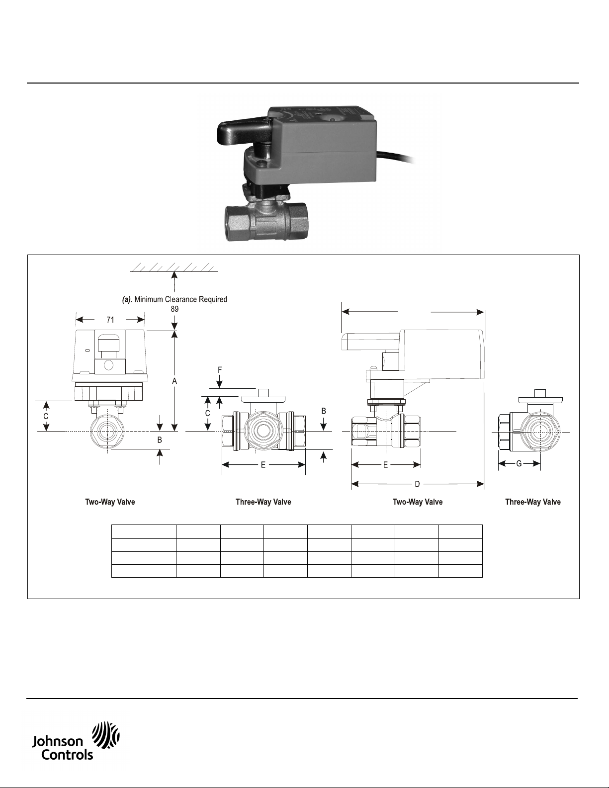
VA9104-AGA-1S / VA9104-IGA-1S / VA9104-IUA-1S / VA9104-GGA-1S
140
Valve Size (DN)*
A
B C D E F G
DN15 98 17 31 129 64 9 32
DN20 98 17 31 133 71 9 36
DN25 100 19 33 141 87 9 43
* (b). On models with the flow-characterizing disk, the disk is located in Port A. Port A must be the Valve inlet.
European Single Point of Contact: NA/SA Single Point of Contact: APAC Single Point of Contact:
JOHNSON CONTROLS
WESTENDHOF 3
45143 ESSEN
GERMANY
JOHNSON CONTROLS
507 E MICHIGAN ST
MILWAUKEE WI 53202
USA
JOHNSON CONTROLS
C/O CONTROLS PRODUCT MANAGEMENT
NO. 22 BLOCK D NEW DISTRICT
WUXI JIANGSU PROVINCE 214142 - CHINA
Electric Non-Spring Return Valve Actuators
Installation Instructions
P/N 14-88360-2331 Rev. G
Issue Date 04 2017
Figure 1: Dimensions in mm
© Copyright 2017 Johnson Controls. All rights reserved. Any unauthorized use or copying is strictly prohibited.
Johnson Controls® is registered trademark of Johnson Controls
All marks herein are the marks of their respective owners.
www.johnsoncontrols.com
Page 2
IS_VA9104-AGA-1S / VA9104-IGA-1S / VA9104-IUA-1S / VA9104-GGA-1S_14-88360-2331_Rev. G_04 2017
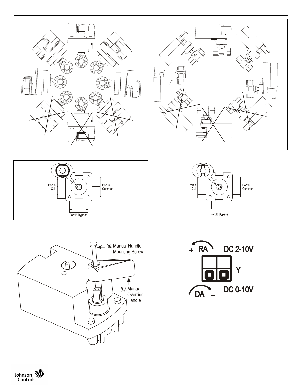
Figure 2: Mounting Positions for Chilled Water and condensing Atmosphere Applications
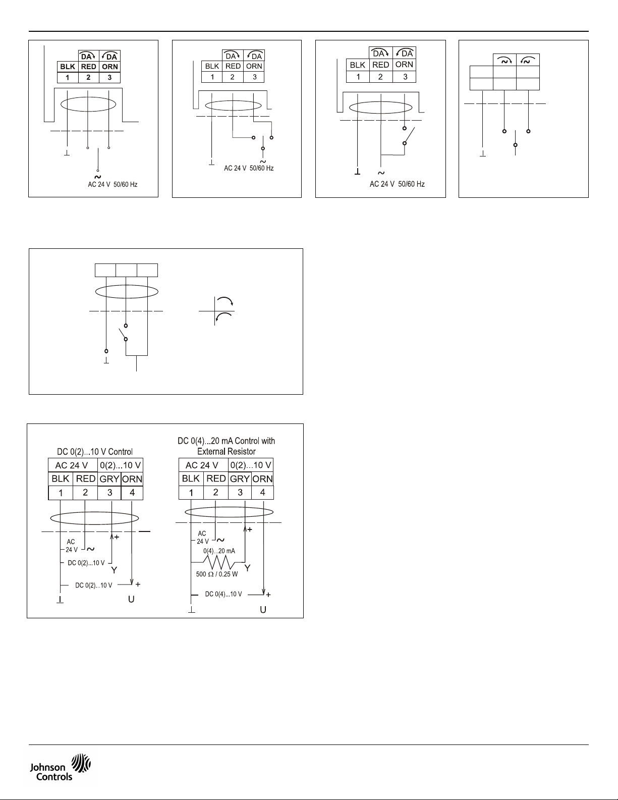
Figure 3: VG1000 Series 3-Way Ball Valve
(Port A Connected to Port C)
Figure 5: Installing the Handle
Figure 4: VG1000 Series 3-Way Ball Valve
(Port B Connected to Port C)
Figure 6: VA9104-GGA-1S Factory Switch Setting
This document is subject to change without notice
Page 3
IS_VA9104-AGA-1S / VA9104-IGA-1S / VA9104-IUA-1S / VA9104-GGA-1S_14-88360-2331_Rev. G_04 2017
BLU
S1
S1
ON DA
RA
OFF
AC 100...240 V 50/60 Hz
BRN ORN
BLU
AC 100...240 V 50/60 Hz
BRN ORN
1 2 3
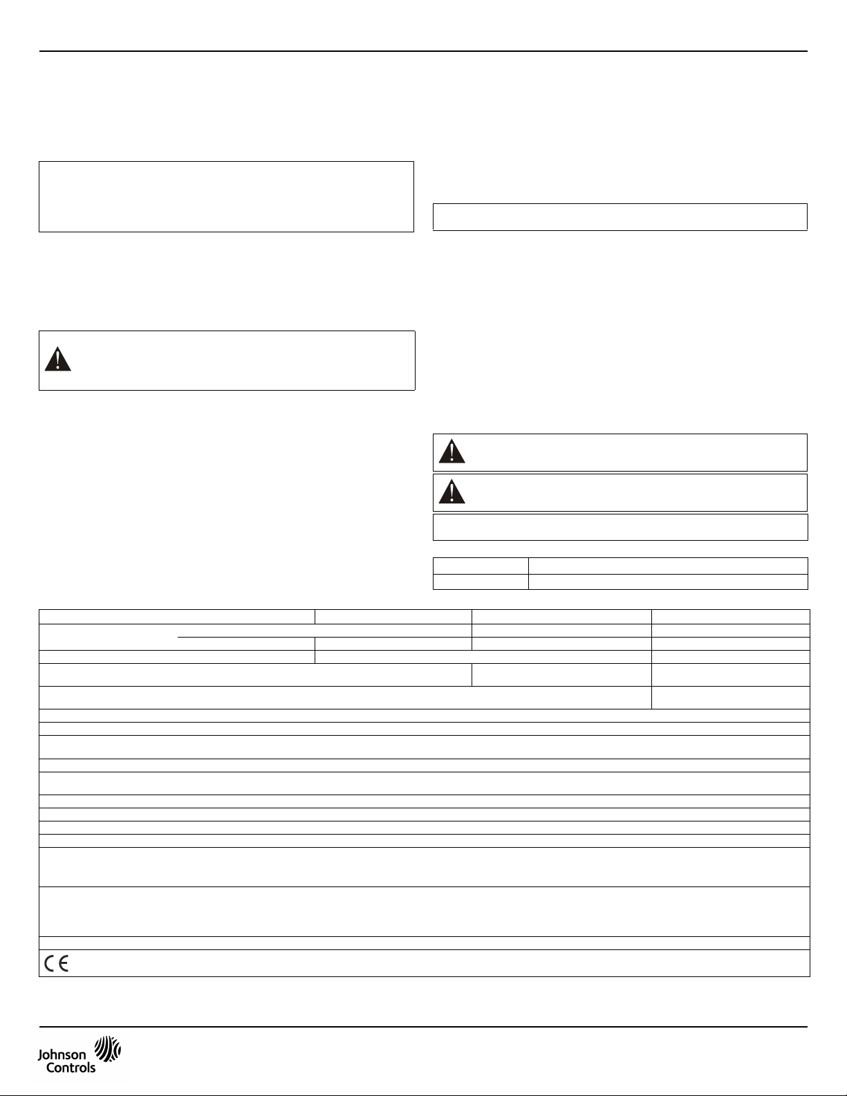
Figure 7: VA9104-AGA-1S
Control Wiring Diagram
Figure 11: VA9104-IUA-1S Control Wiring Diagram ON/OFF
Figure 8: VA9104-IGA-1S
Control Wiring Diagram Floating
Figure 9: VA9104-IGA-1S
Control Wiring Diagram ON/OFF
Figure 10: VA9104-IUA-1S
Control Wiring Diagram Floating
Figure 12: VA9104-GGA-1S Control Wiring Diagram
This document is subject to change without notice
Page 4
English
READ THIS INSTRUCTION SHEET AND THE SAFETY WARNINGS CAREFULLY
General Features
The VA9104 Series Actuators are direct-mount, non-spring return electric valve
actuators that operate on AC 24V or AC 100÷240V power supply. These synchronous,
motor-driven actuators are used to provide accurate positioning on Johnson Controls®
VG1000 Series DN15, DN20, and DN25 ball valves in Heating, Ventilating and Air
Conditioning (HVAC) applications.
The VA9104 Series Electric Non-Spring Return Actuators provide a running torque of 4 Nm.
IMPORTANT: Use this Actuator only to control valves under normal operating
conditions. Where failure or malfunction of the actuator could lead to personal injury
or property damage to the controlled equipment or other property, additional
precautions must be designed into the control system. Incorporate and maintain
other devices such as supervisory or alarm systems or safety or limit controls intended
to warn of, or protect against, failure or malfunction of the actuator.
Figure 1: Dimensions in mm
Installation
Figure 2: Mounting Positions for Chilled Water and condensing Atmosphere
Install the ball valve with the actuator at or above the centerline of the horizontal piping.
Mounting the Actuator
Figure 3: VG1000 Series 3-Way Ball Valve (Port A Connected to Port C)
Figure 4: VG1000 Series 3-Way Ball Valve (Port B Connected to Port C)
Figure 5: Installing the Handle
To mount the actuator to a ball valve:
1. Rotate the valve stem manually several times using an adjustable wrench to break
the torque that may have built up during long-term storage.
Then, rotate the valve stem so that Port A on the valve is open.
Note: Two-way valves in the fully open position have the index marking on the top
of the valve stem, parallel to the direction of flow. Two-way valves in the fully closed
position have the index marking perpendicular to the direction of flow. Three-way valves
feature two index markings on the top of the valve stem, with one of the index markings
parallel to the common port (see Figure 3 and Figure 4).
2. Place the handle on top of the drive shaft as shown in Figure 5.
The handle is keyed and can only be mounted in one orientation.
BEFORE INSTALLING AND SAVE IT FOR FUTURE USE
(a). Minimun Clearance Required
(b). On models with the flow-characterizing disk, the disk is located
in Port A. Port A must be the Valve inlet.
Applications
WARNING: Do not install or use this Actuator in or near environments
where corrosive substances or vapors could be present.
Exposure of the electric actuator to corrosive environments may
damage the internal components of the device, and will void the
warranty.
(a). Manual Handle Mounting Screw
(b). Manual Override Handle
IS_VA9104-AGA-1S / VA9104-IGA-1S / VA9104-IUA-1S / VA9104-GGA-1S_14-88360-2331_Rev. G_04 2017
Technical Specifications
Product Codes
Power Requirements
Control Type
Input Signal
Feedback Signal
Motor Input Impedance
Running Torque
Travel Time
(for 90° of Rotation)
Rotation Range
Cycles
Audible Noise Rating
Electrical Connections
Mechanical Connections
Enclosure
Ambient Conditions
Fluid Temperature Limits
(Actuator and Valve Assembly)
Shipping Weight
Compliance
- Operating
- Storage
- Water
- Steam
VA9104-AGA-1S VA9104-IGA-1S VA-104-IUA-1S VA9104-GGA-1S
AC 24V +25%/-20% at 50/60 Hz AC 100 to 240V -15%/+10% at 50/60 Hz AC 24V +25%/-20% at 50/60 Hz
Floating Control without Timeout ON/OFF and Floating Control with Timeout Modulating
200 ohms Nominal
4 Nm
60 Seconds at 60 Hz
72 Seconds at 50 Hz
93° ±3°, CW or CCW
100,000 Full Stroke Cycles;
2,500,000 Repositions at Rated Running Torque
35 dBA Nominal at 1 m
1.2 m Polyvinyl Chloride (PVC) cable
Up to13 mm Diameter Round Damper Shafts, or 10 mm Square Damper Shafts
IP 42
-20 to 60° C; 90% RH Maximum, Noncondensing
-40 to 85° C; 90% RH Maximum, Noncondensing
VG1205 and VG1805 Series Valves: -30 to +95 °C (140 °C with M9000-561 Thermal Barrier)
Rated for Steam Service only with M9000-561 Thermal Barrier
0.5 Kg
Johnson Controls declares that these products are in compliance with the essential requirements and other relevant provisions of the
EMC Directive and Low Voltage Directive
2.1 VA 3.0 VA 7.5 VA Supply and 0.07 A 3.6 VA
AC 24 V +25%/-20% at 50/60 Hz, SELV or Class II AC 100 to 240V -15%/+10% at 50/60 Hz
3. Insert the M4 x 60 long machine screw into the hole in the handle.
Use a flat blade screwdriver to drive the screw into the drive shaft until the screw
is below the top of the handle.
4. Check that the actuator coupler and handle are in the fully counterclockwise position
as viewed from the top of the actuator. If not, press the actuator gear release
and rotate the handle until the actuator coupler is fully counterclockwise.
5. Install the valve actuator over the ball valve mounting flange.
Depending on the installation, position the assembly in any one of four 90°
increments on the valve.
Note: For proper operation, the actuator must drive the valve counterclockwise to open
Port A when viewed from above the valve.
6. To secure the actuator to the valve, use a flat blade screwdriver.
Recommended torque is 0.9 to 1.4 Nm.
IMPORTANT: Do not overtighten the manual handle mounting screw.
Overtightening may strip the threads resulting in damage to the valve stem threads.
Selecting the direction of rotation
Figure 6: VA9104-GGA-1S Factory Switch Setting
VA9104-GGA actuators are factory set for Direct Acting (DA) mode and for a DC 0 to 10
V input control signal. In DA mode, a minimum control signal drives the actuator to the
full Counterclockwise (CCW) position, and a maximum control signal drives the actuator
to the full Clockwise (CW) position.
For Reverse Acting (RA) operation, a minimum control signal drives the actuator
to the full CW position and a maximum signal drives the actuator to the full CCW
position. To change the factory settings, remove the actuator cover and adjust
the switches on the circuit board.
Wiring
Figure 7: VA9104-AGA-1S Control Wiring Diagram
Figure 8: VA9104-IGA-1S Control Wiring Diagram - Floating
Figure 9: VA9104-IGA-1S Control Wiring Diagram - ON/OFF
Figure 10: VA9104-IUA-1S Control Wiring Diagram - Floating
Figure 11: VA9104-IUA-1S Control Wiring Diagram - ON/OFF
Figure 12: VA9104-GGA-1S Control Wiring Diagram
WARNING: Risk of Electric Shock Disconnect the power supply before
making electrical connections to avoid electric shock.
WARNING: Risk of Property Damage Do not apply power to the system
before checking all wiring connections. Short circuited or improperly
connected wires may result in permanent damage to the equipment.
IMPORTANT: Make all wiring connections in accordance with local, national, and
regional regulations. Do not exceed the electrical ratings of the Actuator.
Accessories
(Order Separetely)
Code Number Description
M9000-550 Mounting Hardware Replacement Kit
--- DC 0(2)...10 V Corresponds to input
Class II
DC 0(2) to 10 V or 0(4) to 20 mA
with field furnished 500 ohm resistor
span selection (DC 10V at 1 mA)
This document is subject to change without notice
1
Page 5

Français
LISEZ ATTENTIVEMENT LES PRÉSENTES INSTRUCTIONS ET LES CONSIGNES
DE SÉCURITÉ AVANT DE PROCÉDER À L’INSTALLATION ET CONSERVEZ-LES
Caractéristiques générales
Les commandes VA9104 sont des commandes électriques de vannes sans rappel par
ressort et à montage direct alimentées en AC 24 V ou AC 100÷240 V. Ces commandes
motorisées synchrones assurent un positionnement précis des vannes à bille Johnson
Controls® VG1000 DN15, DN20 et DN25 dans les applications de chauffage, ventilation
et climatisation (HVAC).
Les commandes électriques sans rappel par ressort VA9104 fonctionnent à un couple
de 4 Nm.
IMPORTANT: N’utilisez cette commande que pour réguler des vannes dans des
conditions de fonctionnement normales. Si les pannes ou défaillances de la
commande sont susceptibles d’entraîner des lésions corporelles, d’endommager
l’équipement régulé ou de provoquer d’autres dégâts matériels, on intégrera des
mesures de sécurité supplémentaires au système de régulation. On incorporera
d’autres dispositifs tels que des systèmes de surveillance ou d’alarme, ou encore des
commandes de sécurité ou de limitation, afin d’avertir ou de protéger les personnes en
cas de panne ou de défaillance de la commande.
Figure 1: Dimensions en mm
Installation
Figure 2: Positions de montage pour les applications en eau réfrigérée et
Installez la vanne à bille et la commande au niveau ou au-dessus de l’axe de la
tuyauterie horizontale.
Montage de la commande
Figure 3: Vanne à bille trois voies VG1000 (port A raccordé au port C)
Figure 4: Vanne à bille trois voies VG1000 (port B raccordé au port C)
Figure 5: Installation de la manette
Pour monter la commande sur une vanne à bille:
1. Faites tourner la tige de la vanne manuellement plusieurs fois à l’aide d’une clé
Remarque: Sur les vannes à deux voies en position entièrement ouverte, le repère
situé en haut de la tige est parallèle au sens d’écoulement. Sur les vannes à deux voies
en position entièrement fermée, ce repère est perpendiculaire au sens d’écoulement.
Les vannes à trois voies possèdent deux repères en haut de la tige, dont l’un est
parallèle au port commun (voir figure 3 et figure 4).
2. Placez la manette en haut de l’arbre de commande, comme illustré à la figure 5.
(a). Jeu minimum obligatoire
(b). Sur les modèles avec disque de caractérisation du débit, le disque est
atmosphère avec condensation
ATTENTION: N’installez pas et n’utilisez pas cette commande dans des
environnements susceptibles de renfermer des substances ou des
vapeurs corrosives, ni à proximité. L’exposition de la commande
électrique à des environnements corrosifs risque d’endommager ses
composants internes et peut ainsi annuler la garantie.
(a). Vis de fixation de la manette de commande manuelle
(b). Manette de commande manuelle de secours
réglable pour rompre le couple qui a pu se former en cas de stockage prolongé.
Faites ensuite tourner la tige de la vanne de manière à ce que son port A soit ouvert.
La manette est clavetée et ne peut être montée que dans un sens.
AUX FINS D’UTILISATION ULTÉRIEURE
situé dans le port A, qui doit correspondre à l’entrée de la vanne.
IS_VA9104-AGA-1S / VA9104-IGA-1S / VA9104-IUA-1S / VA9104-GGA-1S_14-88360-2331_Rev. G_04 2017
3. Insérez la vis usinée longue M4 x 60 dans l’orifice de la manette.
Utilisez un tournevis à lame plate pour faire pénétrer la vis dans l’arbre de commande
jusqu’à ce qu’elle se trouve sous la partie supérieure de la manette.
4. Vérifiez que le coupleur de la commande et la manette sont en position entièrement
anti-horaire, vus depuis le dessus de la commande. Si ce n’est pas le cas, appuyez
sur le dispositif de déverrouillage de l’engrenage de la commande et faites tourner la
manette jusqu’à ce que le coupleur se trouve entièrement dans le sens anti-horaire.
5. Installez la commande de la vanne sur la bride de montage de la vanne à bille.
Selon l’installation, positionnez l’ensemble au niveau de l’un des quatre incréments
de 90° sur la vanne.
Remarque: Pour que le système fonctionne convenablement, la commande doit piloter
la vanne dans le sens anti-horaire pour ouvrir le port A, vue depuis le dessus de la
vanne.
6. Pour fixer la commande sur la vanne, utilisez un tournevis à lame plate.
Le couple conseillé est de 0,9 à 1,4 Nm.
IMPORTANT: Ne serrez pas trop la vis de fixation de la manette de commande
manuelle, vous risqueriez de dénuder les filets et d’endommager le filetage de la tige
de la vanne.
Sélection du sens de rotation
Figure 6: Réglage d’usine du commutateur VA9104-GGA-1S
Les commandes VA9104-GGA sont réglées en usine pour un fonctionnement direct
(DA) et un signal de commande en entrée de 0 à 10 VDC. En mode DA, un signal de
régulation minimum place la commande en position entièrement anti-horaire et un
signal de régulation maximum la place en position entièrement horaire.
En fonctionnement inversé (RA), un signal de régulation minimum place la commande
en position entièrement horaire et un signal maximum la place en position entièrement
anti-horaire. Pour modifier les paramètres d’usine, retirez le couvercle de la commande
et réglez les commutateurs de la carte électronique.
Câblage
Figure 7: Schéma de câblage de la commande VA9104-AGA-1S
Figure 8: Schéma de câblage de la commande flottante VA9104-IGA-1S
Figure 9: Schéma de câblage de la commande marche/arrêt VA9104-IGA-1S
Figure 10: Schéma de câblage de la commande flottante VA9104-IUA-1S
Figure 11: Schéma de câblage de la commande marche/arrêt VA9104-IUA-1S
Figure 12: Schéma de câblage de la commande VA9104-GGA-1S
ATTENTION: Risque d’électrocution. Débranchez l’alimentation avant
de procéder aux raccordements électriques afin d’éviter les risques
d’électrocution.
ATTENTION: Risque de dégâts matériels. Ne mettez pas le système
sous tension avant d’avoir vérifié tous les raccordements.
Des fils en court-circuit ou mal raccordés pourraient endommager
l’équipement de façon irrémédiable.
IMPORTANT: Effectuez tous les raccordements de câblage en respectant la
réglementation locale, nationale et régionale. Ne dépassez pas les valeurs électriques
nominales de la commande.
Accessoires
(à commander séparément)
Référence Description
M9000-550 Kit de matériel de fixation de rechange
Caractéristiques techniques
Codes produits VA9104-AGA-1S VA9104-IGA-1S VA9104-IUA-1S VA9104-GGA-1S
Alimentation
Type de régulation
Signal d’entrée
Signal de feed-back
Impédance d’entrée du moteur
Couple de fonctionnement
Temps de course
(pour une rotation de 90°)
Plage de rotation
Cycles
Niveau sonore audible nominal
Raccordements électriques
Raccords mécaniques
Enceinte
Conditions ambiantes
Limites de température des fluides
(ensemble commande et vanne)
Poids d’expédition
- Fonctionnement
- Stockage
- Vapeur
Conformité
Commande flottante sans
Valeur nominale 200 ohms
4 Nm
60 s à 60 Hz
72 s à 50 Hz
93° ±3°, sens horaire ou anti-horaire
100 000 cycles à pleine course
2 500 000 repositionnements au couple de fonctionnement nominal
35 dBA nominaux à 1 m
Câble en PVC (polychlorure de vinyle) de 1,2 m
Axes de clapet ronds de diamètre max. 13 mm ou axes de clapet carrés de 10 mm max.
IP 42
-20 à 60 °C ; 90 % HR maximum, sans condensation
-40 à 85 °C ; 90 % HR maximum, sans condensation
Vannes VG1205 et VG1805: -30 à +95 °C 140 °C avec la barrière thermique M9000-561)
- Eau
Valeurs disponibles uniquement avec la barrière thermique M9000-561
0,5 kg
Johnson Controls déclare que ces produits sont conformes aux exigences essentielles et autres dispositions pertinentes de la Directive et de la Directive
basse tension.
24 VAC +25 %/-20 % à 50/60 Hz 100 à 240 VAC -15 %/+10 % à 50/60 Hz 24 VAC +25 %/-20 % à 50/60 Hz
2,1 VA 3,0 VA 7.5 VA Alimentation électrique et 0.07 A 3,6 VA
temporisation
24 VAC +25 %/-20 % à 50/60 Hz, SELV ou Classe II
Commande marche-arrêt et flottante avec temporisation Modulation
100 à 240 VAC -15%/+10% à 50/60 Hz,
--- 0(2) à 10 VDC Correspond à la sélection
Classe II
Ce document peut être sujet à modification sans préavis
0(2) à 10 VDC ou 0(4) à 20 mA
avec résistance de 500 ohms
fournie sur site
de la plage d’entrée (10 VDC à 1 mA)
2
Page 6

Deutsch
LESEN SIE DIESE ANLEITUNG UND DIE SICHERHEITSHINWEISE VOR DER
INSTALLATION SORGFÄLTIG DURCH UND BEWAHREN SIE SIE FÜR SPÄTERE
Allgemeine Merkmale
Bei den Stellantrieben der Serie VA9104 handelt es sich um direkte elektrische
Ventilstellantriebe ohne Federrücklauf, die mit 24V AC oder 100÷240V AC
Nennspannung betrieben werden. Diese synchronen, motorgesteuerten Stellantriebe
werden verwendet, um eine exakte Positionierung von Johnson Controls® Kugelventilen
der Serien VG1000 DN15, DN20 und DN25 in Heizungs-, Lüftungs- und
Klimaanlagensystemen zu gewährleisten.
Die elektrischen Stellantriebe ohne Federrücklauf der Serie VA9104 unterstützen ein
Betriebsdrehmoment von 4 Nm.
WICHTIG: Verwenden Sie diesen Stellantrieb nur, um Ventile unter normalen
Betriebsbedingungen zu steuern. Wenn der Ausfall oder eine Fehlfunktion des
Stellantriebs zu Personenschäden oder Sachbeschädigungen der gesteuerten Anlage
oder anderer Gegenstände führen könnte, müssen in dem Regelungssystem
zusätzliche Vorsichtsmaßnahmen vorgesehen werden. Bauen Sie andere Geräte ein,
wie beispielsweise Überwachungs- oder Alarmsysteme oder Sicherheits- oder
Begrenzerelemente, und achten Sie auf ihren fehlerfreien Betrieb, um vor Ausfall oder
Fehlfunktionen des Stellantriebs zu warnen oder davor zu schützen.
Abbildung 1: Abmessungen in mm
(a). Mindestabstand erforderlich
(b). Bei Modellen mit Scheibe zur Bestimmung der Flusseigenschaften
befindet sich die Scheibe in Anschluss A. Anschluss A muss der
Ventileingang sein.
Montage
Abbildung 2: Montagepositionen für Applikationen mit Kühlwasser und
Bringen Sie das Kugelventil mit dem Stellantrieb an oder oberhalb der Mittellinie der
horizontalen Rohrleitung an.
Kondensatfeuchte
ACHTUNG: Montieren oder verwenden Sie diesen Stellantrieb nicht in
Umgebungen oder in der Nähe von Umgebungen, wo korrosive
Substanzen oder Dämpfe auftreten können.
Wenn der elektrische Stellantrieb korrosiven Umgebungen ausgesetzt
ist, können die internen Komponenten des Geräts beschädigt werden
und die Garantie erlischt.
Montage des Stellantriebs
Abbildung 3: Dreiwegekugelventil der Serie VG1000
Abbildung 4: Dreiwegekugelventil der Serie VG1000
Abbildung 5: Griffmontage
Um den Stellantrieb auf einem Kugelventil zu montieren, gehen Sie wie folgt vor:
1. Drehen Sie den Ventilschaft unter Verwendung eines verstellbaren
Einmaulschlüssels mehrfach von Hand, um das Drehmoment zu lösen, das sich
möglicherweise während der langen Lagerung aufgebaut hat.
Anschließend drehen Sie den Ventilschaft so, dass Anschluss A am Ventil geöffnet ist.
Hinweis: Zweiwegeventile in vollständig geöffneter Position haben die Indexmarkierung
oben am Ventilschaft, parallel zur Flussrichtung. Zweiwegeventile in vollständig
geschlossener Position haben die Indexmarkierung senkrecht zur Flussrichtung.
Dreiwegeventile besitzen zwei Markierungen oben am Ventilschaft. Eine dieser
Markierungen steht parallel zum gemeinsamen Anschluss (siehe Abb. 3 und Abb 4).
(Anschluss A mit Anschluss C verbunden)
(Anschluss B mit Anschluss C verbunden)
(a). Montageschraube für den Handgriff
(b). Griff für die Handbetätigung
REFERENZZWECKE AUF
IS_VA9104-AGA-1S / VA9104-IGA-1S / VA9104-IUA-1S / VA9104-GGA-1S_14-88360-2331_Rev. G_04 2017
2. Bringen Sie den Griff oben am Achsenschaft an, wie in Abbildung 5 gezeigt.
Der Griff ist speziell gekennzeichnet und kann nur in einer Richtung montiert werden.
3. Setzen Sie die lange Metallgewindeschraube M4x60 in die Bohrung im Griff ein.
Drehen Sie die Schraube mit Hilfe eines Flachkopfschraubendrehers in den
Achsenschaft, bis sie unter der Griffoberseite verschwunden ist.
4. Stellen Sie sicher, dass der Stellantriebsadapter und der Griff vollständig gegen den
Uhrzeigersinn stehen, wenn man von der Oberseite des Stellantriebs darauf blickt.
Andernfalls drücken Sie die Antriebsentriegelung des Stellantriebs und drehen den
Griff, bis der Stellantriebsadapter vollständig gegen den Uhrzeigersinn positioniert ist.
5. Bringen Sie den Ventilstellantrieb über dem Montageflansch des Kugelventils an.
Platzieren Sie den Bausatz abhängig von der jeweiligen Montage in einem von vier
90°-Schritten auf dem Ventil.
Hinweis: Damit der Stellantrieb richtig funktioniert, muss er das Ventil gegen den
Uhrzeigersinn drehen, um Anschluss A zu öffnen (Sicht von oben auf das Ventil).
6. Um den Stellantrieb am Ventil zu sichern, verwenden Sie einen
Flachkopfschraubendreher. Das empfohlene Drehmoment beträgt 0,9 bis 1,4 Nm.
WICHTIG: Ziehen Sie die Montageschraube für den Handgriff nicht zu fest an.
Durch das Überdrehen können die Gewinde brechen, was zu einer Beschädigung der
Gewinde am Ventilschaft führt.
Wahl der Drehrichtung
Abbildung 6: VA9104-GGA-1S Werksseitige Schalterstellungen
VA9104-GGA-Stellantriebe sind werksseitig auf direktwirkenden Betrieb (DA, Direct
Acting) und für ein Eingangssteuersignal von 0 bis 10 V DC eingestellt. Im DA-Modus
steuert ein minimales Steuersignal den Stellantrieb vollständig gegen den
Uhrzeigersinn, und ein maximales Steuersignal steuert den Stellantrieb vollständig im
Uhrzeigersinn.
Für den RA-Betrieb (Reverse Acting, Umkehrbetrieb) steuert ein minimales Steuersignal
den Stellantrieb vollständig im Uhrzeigersinn, und ein maximales Signal steuert den
Stellantrieb vollständig gegen den Uhrzeigersinn. Um die Werkseinstellungen zu
verändern, entfernen Sie die Abdeckung des Stellantriebs und passen die Schalter auf
der Platine an.
Anschluss
Abbildung 7: VA9104-AGA-1S-Steuerung Schaltplan
Abbildung 8: VA9104-IGA-1S-Steuerung Schaltplan - 3-Punkt
Abbildung 9: VA9104-IGA-1S-Steuerung Schaltplan - AUF/ZU
Abbildung 10: VA9104-IUA-1S-Steuerung Schaltplan - 3-Punkt
Abbildung 11: VA9104-IUA-1S-Steuerung Schaltplan - AUF/ZU
Abbildung 12: VA9104-GGA-1S-Steuerung Schaltplan
ACHTUNG: Stromschlaggefahr – Trennen Sie das Gerät von der
Stromversorgung, bevor Sie elektrische Verbindungen einrichten, um
einen Stromschlag zu vermeiden.
ACHTUNG: Risiko von Sachschäden – Setzen Sie das System erst dann
unter Spannung, wenn Sie alle verdrahteten Verbindungen überprüft
haben. Kurzgeschlossene oder fehlerhaft angeschlossene Drähte
können zu einer dauerhaften Beschädigung der Anlage führen.
WICHTIG: Nehmen Sie alle Verdrahtungsverbindungen gemäß lokaler, nationaler und
regionaler Vorschriften vor. Überschreiten Sie keinesfalls die elektrischen Kennwerte
des Stellantriebs.
Zubehör
Teilenummer Beschreibung
M9000-550 Austauschbausatz Montagehardware
(separat zu bestellen)
Technische Daten
Produktnamen
Leistungsaufnahme AC 24V +25 %/-20 % bei 50/60 Hz AC 100 bis 240V -15%/+10 % bei 50/60 Hz AC 24V +25 %/-20 % bei 50/60 Hz
Steuerungstyp 3-Punkt-Steuerung ohne Zeitabschaltung AUF/ZU- oder 3-Punkt-Steuerung mit Zeitabschaltung Modulierende Steuerung
Eingangssignal AC 24 V +25 %/-20 % bei 50/60 Hz, SELV oder Klasse II
Feedback-Signal --- --- ---
Motoreingangsimpedanz 200 Ohm nominal
Betriebsdrehmoment 4 Nm
Laufzeit
(für 90° Drehung)
Drehbereich 93° ±3°, im Uhrzeigersinn oder gegen den Uhrzeigersinn
Zyklen
Schallpegelmessung 35 dBA nominal bei 1 m
Elektrische Anschlüsse 1,2 m PVC-Kabel (Polyvinylchlorid)
Mechanische Anschlüsse Bis zu 13 mm Durchmesser für runde Klappenachsen oder 10 mm für Vierkant-Klappenachsen
Gehäuse IP 42
Umgebungsbedingungen
Grenzwerte für die
Flüssigkeitstemperatur
(Stellantrieb und Ventilbausatz)
Versandgewicht 0,5 kg
Konformität
- im Betrieb -20 bis 60 °C; 90 % relative Luftfeuchtigkeit, nicht kondensierend
- Lagerung -40 bis 85 °C; 90 % relative Luftfeuchtigkeit, nicht kondensierend
- Wasser Ventile der Serien VG1205 und VG1805: -30 bis +95 °C (140 °C mit M9000-561 Wärmeschutz)
- Dampf Für Dampf Anwendungen zugelassen nur mit M9000-561 Wärmeschutz
VA9104-AGA-1S VA9104-IGA-1S VA9104-IUA-1S VA9104-GGA-1S
2,1 VA 3,0 VA 7.5 VA Nennspannung und 0.07 A 3,6 VA
AC 100 bis 240V -15%/+10% bei 50/60 Hz
60 Sekunden bei 60 Hz
72 Sekunden bei 50 Hz
100.000 volle Hubzyklen;
2.500.000 Neupositionierungen beim Nenndrehmoment für den Betrieb
Johnson Controls erklärt, dass diese Produkte konform sind mit den wesentlichen Anforderungen und sonstigen anwendbaren Bestimmungen der EMVRichtlinie und der Niederspannungsrichtlinie
Klasse II
DC 0(2) bis 10 V oder 0(4) bis 20 mA
mit vor Ort bereitgestelltem
Widerstand mit 500 Ohm
DC 0(2)...10 V Entspricht dem
ausgewählten Eingangssignalbereich
(DC 10V bei 1 mA)
Änderungen des Dokuments vorbehalten
3
Page 7

Italiano
LEGGERE ATTENTAMENTE QUESTE ISTRUZIONI E LE AVVERTENZE PRIMA
DELL'INSTALLAZIONE E CONSERVARLE PER USO FUTURO
Funzioni generali
Gli attuatori della serie VA9104 sono attuatori per valvole elettrici, senza ritorno a molla,
a montaggio diretto che funzionano con un'alimentazione AC di 24 V o AC 100÷240V.
Questi attuatori sincroni a motore sono usati per il posizionamento corretto nelle valvole
a sfera DN15, DN20 e DN25 Johnson Controls® della serie VG1000 in applicazioni
HVAC (Heating, Ventilating and Air Conditioning, ovvero riscaldamento, ventilazione e
condizionamento dell'aria).
Gli attuatori elettrici, senza molla di ritorno, della serie VA9104 offrono una coppia di
funzionamento di 4 Nm.
IMPORTANTE: Utilizzare questi attuatori per controllare le valvole in condizioni di
funzionamento normali. Qualora un guasto o un malfunzionamento dell'attuatore possa
provocare lesioni personali o danni all'apparecchiatura controllata o altri danni materiali,
è necessario adottare precauzioni aggiuntive nel sistema di controllo. Includere e
gestire altri dispositivi, ad esempio sistemi di supervisione o di allarme oppure controlli
di limitazione o sicurezza che hanno lo scopo di avvisare o proteggere da guasti o
malfunzionamenti dell'attuatore.
Figura 1: Dimensioni in mm
Installazione
Figura 2: Posizioni di montaggio per applicazioni ad acqua refrigerata e di
Installare la valvola a sfera con l'attuatore posizionato in corrispondenza o sopra la linea
centrale della tubazione orizzontale.
Montaggio dell'attuatore
Figura 3: Valvola a sfera a tre vie serie VG1000 (porta A connessa alla porta C)
Figura 4: Valvola a sfera a tre vie serie VG1000 (porta B connessa alla porta C)
Figura 5: Installazione della maniglia
Per montare l'attuatore su una valvola a sfera:
1. Ruotare lo stelo della valvola diverse volte utilizzando una chiave inglese regolabile
Nota: Nelle valvole a due vie in posizione completamente aperta, il contrassegno sulla
parte superiore dello stelo della valvola è parallelo alla direzione del flusso. Nelle valvole
a due vie in posizione completamente chiusa, il contrassegno è perpendicolare alla
direzione del flusso. Nelle valvole a tre vie sono presenti due contrassegni nella parte
superiore dello stelo della valvola, uno dei quali è parallelo alla porta comune (vedere
figure 3 e 4).
2. Posizionare la maniglia sulla parte superiore dell'albero motore, come mostrato nella
(a). Distanza minima richiesta
(b). Nei modelli dotati di disco di caratterizzazione del flusso, il disco si trova
nella porta A. La porta A deve essere l'entrata della valvola.
condensazione
AVVERTENZA: Non installare o utilizzare questo attuatore all'interno o in
prossimità di ambienti in cui possono essere presenti sostanze o vapori
corrosivi.
L'esposizione dell'attuatore ad ambienti corrosivi può danneggiare i
componenti interni del dispositivo e rendere nulla la garanzia.
(a). Vite di montaggio maniglia manuale
(b). Maniglia comando manuale
per rompere la coppia che potrebbe essersi creata durante il periodo di
immagazzinaggio.
Quindi, ruotare lo stelo della valvola in modo da aprire la porta A sulla valvola.
figura 5.
La maniglia è inchiavettata e può essere montata con un solo orientamento.
IS_VA9104-AGA-1S / VA9104-IGA-1S / VA9104-IUA-1S / VA9104-GGA-1S_14-88360-2331_Rev. G_04 2017
3. Inserire la vite senza dado M4 x 60 nel foro della maniglia.
Utilizzare un cacciavite a punta piatta per avvitare la vite nell'albero motore fino a
quando la vite non si trova sotto la parte superiore della maniglia.
4. Verificare che il giunto dell'attuatore e la maniglia si trovino nella posizione di fondo in
senso antiorario, nella vista da sopra l'attuatore. In caso contrario, premere la leva di
sblocco del movimento dell'attuatore e ruotare la maniglia fino a quando il giunto
dell'attuatore non si trova nella posizione di fondo in senso antiorario.
5. Installare l'attuatore per valvole sopra la flangia di montaggio della valvola a sfera.
In base all'installazione, posizionare l'assieme in uno dei quattro incrementi di 90°
sulla valvola.
Nota: Per il corretto funzionamento, l'attuatore deve guidare la valvola in senso
antiorario per aprire la porta A, nella vista da sopra la valvola.
6. Per fissare l'attuatore alla valvola, utilizzare un cacciavite a punta piatta.
La coppia consigliata è compresa tra 0,9 e 1,4 Nm.
IMPORTANTE: Non serrare troppo la vite di montaggio della maniglia manuale.
In caso contrario, i filetti potrebbero strapparsi e causare danni alla filettatura dello stelo
della valvola.
Selezione della direzione di rotazione
Figura 6: VA9104-GGA-1S Impostazione interruttore predefinita
Gli attuatori VA9104-GGA sono preimpostati per la modalità DA (Direct Acting) e per un
segnale di controllo di ingresso DC da 0 a 10 V. Nella modalità DA, un segnale di
controllo minimo guida l'attuatore nella posizione di fondo in senso antiorario, mentre un
segnale di controllo massimo guida l'attuatore nella posizione di fondo in senso orario.
Nel funzionamento RA (Reverse Acting), un segnale di controllo minimo guida
l'attuatore nella posizione di fondo in senso orario, mentre un segnale di controllo
massimo guida l'attuatore nella posizione di fondo in senso antiorario. Per modificare le
impostazioni predefinite, rimuovere la copertura dell'attuatore e regolare gli interruttori
sulla scheda.
Cablaggio
Figura 7: VA9104-AGA-1S Schema di cablaggio controllo
Figura 8: VA9104-IGA-1S Schema di cablaggio controllo - Flottante
Figura 9: VA9104-IGA-1S Schema di cablaggio controllo - ON/OFF
Figura 10: VA9104-IUA-1S Schema di cablaggio controllo - Flottante
Figura 11: VA9104-IUA-1S Schema di cablaggio controllo - ON/OFF
Figura 12: VA9104-GGA-1S Schema di cablaggio controllo
AVVERTENZA: Rischio di scossa elettrica. Scollegare l'alimentazione
prima di eseguire le connessioni elettriche per evitare il rischio di
scosse elettriche.
AVVERTENZA: Rischio di danni alla proprietà. Non alimentare il sistema
prima di aver controllato tutte le connessioni. Fili cortocircuitati o non
correttamente collegati possono causare danni permanenti
all'apparecchiatura.
IMPORTANTE: Effettuare tutti i cablaggi in conformità alle normative locali, nazionali e
regionali. Non superare le caratteristiche nominali elettriche dell'attuatore.
Accessori
(ordinati separatamente)
Codice Descrizione
M9000-550
Kit di montaggio hardware sostitutivo
Specifiche tecniche
Codici prodotti
Requisiti di alimentazione AC 24 V +25% / -20% a 50/60 Hz AC 100 a 240 V -15%/+10% a 50/60 Hz AC 24 V +25% / -20% a 50/60 Hz
Tipo di controllo Controllo flottante senza timeout Controllo ON/OFF e flottante senza timeout Modulante
Segnale di ingresso AC 24 V +25% / -20% a 50/60 Hz, SELV o Classe II AC 100 a 240 V -15%/-10% a 50/60 Hz,
Segnale di feedback --- --- --- DC 0(2)...10 V Corrisponde all'ampiezza
Impedenza di ingresso motore 200 ohm nominale
Coppia di funzionamento 4 Nm
Tempo corsa
(per una rotazione di 90°)
Intervallo di rotazione 93° ±3°, senso orario o antiorario
Cicli 100.000 cicli a corsa completa;
Classificazione rumore
percepibile
Connessioni elettriche Cavo PVC (Polyvinyl Chloride) di 1,2 m
Connessioni meccaniche Alberi della serranda tondi fino a 13 mm, o alberi della serranda quadrati fino a 10 mm.
Contenitore IP 42
Condizioni ambientali
Limiti di temperatura del fluido
(assieme attuatore e valvola)
Peso di spedizione 0,5 Kg
- Funzionamento Da -20 a 60 °C; 90% umidità relativa massima, senza condensa
- Conservazione Da -40 a 85 °C; 90% umidità relativa massima, senza condensa
- Acqua Valvole serie VG1205 e VG1805: da -30 a +95 °C (140 °C con Barriera Termica M9000-561)
- Vapore Approvato per applicazioni con vapore solo con Barriera Termica M9000-561
Conformità
VA9104-AGA-1S VA9104-IGA-1S VA9104-IUA-1S VA9104-GGA-1S
2,1 VA 3,0 VA 7.5 VA alimentazione e 0.07 A 3,6 VA
SELV Classe II
60 secondi a 60 Hz
72 secondi a 50 Hz
2.500.000 riposizionamenti alla coppia di funzionamento stimata
35 dBA nominale a 1 m
Johnson Controls dichiara che questi prodotti sono conformi ai requisiti fondamentali ed altre relative disposizioni della Direttiva EMC e della Direttiva bassa
tensione
DC 0(2) - 10 V o 0(4) - 20 mA
con resistenza di 500 ohm
del segnale di ingresso selezionata
(DC 10 V a 1 mA)
Questo documento può essere soggetto a modifiche senza preavviso
4
Page 8

Español
ANTES DE LA INSTALACIÓN, LEA ATENTAMENTE ESTAS INSTRUCCIONES Y
LAS ADVERTENCIAS DE SEGURIDAD, Y CONSÉRVELAS PARA SU USO FUTURO
Características generales
Los actuadores de la serie VA9104 son actuadores eléctricos de montaje directo con
válvula de retroceso sin muelle que funcionan a 24 VAC o 100÷240 VAC fuente de
alimentación. Estos actuadores sincrónicos accionados por motor se utilizan para
facilitar una colocación precisa en las válvulas esféricas Johnson Controls® DN15,
DN20 y DN25 de la serie VG1000 en aplicaciones de calefacción, ventilación y aire
acondicionado.
Los actuadores eléctricos de retroceso sin muelle de la serie VA9104 proporcionan un par
de funcionamiento de 4 Nm.
IMPORTANTE: Utilice este actuador únicamente para controlar las válvulas en
condiciones normales de funcionamiento. En el caso de que un fallo o un
funcionamiento defectuoso del actuador puedan provocar lesiones personales o daños
en el equipo controlado o en otros objetos, se deben diseñar precauciones adicionales
en el sistema de control. Incorpore y realice el mantenimiento de otros dispositivos,
como sistemas de alarma o supervisión, o bien controles de límites o de seguridad, con
el fin de advertir de fallos o de un funcionamiento defectuoso del actuador y proteger de
ellos.
Figura 1: Dimensiones en mm
Instalación
Figura 2: Posiciones de montaje para aplicaciones en atmósfera con
Instale la válvula esférica con el actuador a la altura de la línea central de la
canalización horizontal o por encima de esa línea.
Montaje del actuador
Figura 3: Válvula esférica de tres vías de la serie VG1000 (lumbrera A conectada
Figura 4: Válvula esférica de tres vías de la serie VG1000 (lumbrera B conectada
Figura 5: Instalación del mango
Para montar el actuador en una válvula esférica:
1. Gire manualmente el vástago de la válvula varias veces con una llave ajustable para
Nota: Las válvulas de dos vías en posición completamente abierta presentan la marca
indicadora encima del vástago de la válvula, en paralelo a la dirección del caudal. Las
válvulas de dos vías en posición completamente cerrada presentan la marca indicadora
en posición perpendicular a la dirección del caudal. Las válvulas de tres vías presentan
dos marcas indicadoras encima del vástago de la válvula, con una de las marcas
indicadoras orientada en paralelo a la lumbrera común (consulte la figura 3 y la figura 4).
(a). Holgura mínima necesaria
(b). En los modelos con disco de caracterización de flujo, el disco se
encuentra en la lumbrera A. La lumbrera A debe corresponder a la
entrada de la válvula.
condensación y agua refrigerada
ADVERTENCIA: No instale ni utilice este actuador en entornos en los
que pudiera haber vapores o sustancias corrosivas ni en sus
inmediaciones.
La exposición del actuador eléctrico a entornos corrosivos podría dañar
los componentes internos del dispositivo y anular la garantía.
a la lumbrera C)
a la lumbrera C)
(a). Tornillo de montaje manual del mango
(b). Mango de control manual
neutralizar el par que pueda haberse generado durante un almacenamiento de larga
duración.
A continuación, gire el vástago de la válvula de manera que la lumbrera A de la
válvula quede abierta.
IS_VA9104-AGA-1S / VA9104-IGA-1S / VA9104-IUA-1S / VA9104-GGA-1S_14-88360-2331_Rev. G_04 2017
2. Coloque el mango encima del eje impulsor, tal como se muestra en la figura 5.
El mango está acuñado y sólo se puede montar en una orientación.
3. Introduzca el tornillo largo para metales M4 x 60 en el orificio del mango.
Utilice un destornillador plano para introducir el tornillo en el eje impulsor hasta que
se encuentre por debajo de la parte superior del mango.
4. Compruebe que el acoplador del actuador y el mango se encuentran en posición de
giro completo en sentido contrario al de las agujas del reloj si se mira desde encima
del actuador. Si no es así, pulse la palanca de liberación del engranaje y gire el
mango hasta que el acoplador del actuador quede en posición de giro contrario al
sentido de las agujas del reloj.
5. Instale el actuador de válvula sobre la brida de montaje de la válvula esférica.
En función de la instalación, coloque el conjunto en cualquiera de los cuatro pasos
de 90° en la válvula.
Nota: Para un funcionamiento correcto, el actuador debe empujar la válvula en sentido
contrario al de las agujas del reloj para abrir la lumbrera A si se mira desde encima de la
válvula.
6. Para fijar el actuador a la válvula, utilice un destornillador plano.
Se recomienda un par de entre 0,9 y 1,4 Nm.
IMPORTANTE: No apriete excesivamente el tornillo de montaje del mango de control
manual. Si se aprieta excesivamente, se podría dañar la rosca del vástago de válvula.
Selección de la dirección de giro
Figura 6: Configuración de interruptores de fábrica del VA9104-GGA-1S
Los actuadores VA9104-GGA están configurados de fábrica para el modo de acción
directa (DA) y para una señal de control de entrada de 0 a 10 VDC. En el modo DA, una
señal mínima de control lleva al actuador a la posición de giro completo en sentido
contrario al de las agujas del reloj, mientras que una señal de control máxima lleva al
actuador a la posición de giro completo en el sentido de las agujas el reloj.
Para el funcionamiento de acción inversa (RA), una señal de control mínima lleva al
actuador a la posición de giro completo en el sentido de las agujas del reloj, y una señal
máxima lleva al actuador a la posición de giro completo en sentido contrario al de las
agujas del reloj. Para cambiar la configuración de fábrica, retire la cubierta del actuador
y ajuste los interruptores en la placa del circuito.
Cableado
Figura 7: Diagrama de cableado de control del VA9104-AGA-1S
Figura 8: Diagrama de cableado de control del VA9104-IGA-1S - flotante
Figura 9: Diagrama de cableado de control del VA9104-IGA-1S – ON/OFF
Figura 10: Diagrama de cableado de control del VA9104-IUA-1S - flotante
Figura 11: Diagrama de cableado de control del VA9104-IUA-1S – ON/OFF
Figura 12: Diagrama de cableado de control del VA9104-GGA-1S
ADVERTENCIA: Riesgo de descarga eléctrica. A fin de evitar descargas
eléctricas, desconecte la fuente de alimentación antes de establecer
conexiones.
ADVERTENCIA: Riesgo de daños materiales. No conecte a la corriente el
sistema antes de comprobar todas las conexiones del cableado. La
presencia de cables cortocircuitados o mal conectados puede dañar el
equipo de forma permanente.
IMPORTANTE: Realice todas las conexiones de cableado según las normativas
locales, nacionales y regionales. No exceda los márgenes de las especificaciones
eléctricas del actuador.
Accesorios
(se encargan por separado)
Número de código Descripción
M9000-550 Kit de reemplazo de hardware de montaje
Especificaciones técnicas
Códigos de producto
Requisitos energéticos 24 VCA +25%/-20% a 50/60 Hz 100 a 240 VCA -15%/+10% a 50/60 Hz 24 VCA +25%/-20% a 50/60 Hz
Tipo de control Control flotante sin tiempo de espera Control ON/OFF y flotante con tiempo de espera Modulación
Señal de entrada 24 VCA +25%/-20% a 50/60 Hz, Clase II o SELV
Señal de retroalimentación
(feedback)
Impedancia de entrada del motor 200 ohmios (nominal)
Par de funcionamiento 4 Nm
Tiempo de recorrido
(para rotación de 90°)
Rango de giro 93° ±3°, a la derecha o a la izquierda
Ciclos 100.000 ciclos de carrera completos;
Nivel de potencia audible 35 dBA (nominal) a 1 m
Conexiones eléctricas Cable de cloruro de polivinilo (PVC) de 1,2 m
Conexiones mecánicas Ejes reguladores redondos de hasta 13 mm de diámetro o ejes reguladores cuadrados de 10 mm
Caja IP 42
Condiciones ambientales
Límites de la temperatura
del fluido (conjunto de actuador
y válvula)
Peso de envío 0,5 kg
- En funcionamiento -20 a 60 °C; 90% HR máxima, sin condensación
- Almacenamiento -40 a 85 °C; 90% HR máxima, sin condensación
- Agua Válvulas de las series VG1205 y VG1805: -30 a +95 °C (140 °C con M9000-561 Barrera térmica)
- Vapor Aprobado para su uso con vapor sólo con M9000-561 Barrera Térmica
Conforme con
VA9104-AGA-1S VA9104-IGA-1S VA9104-IUA-1S VA9104-GGA-1S
2,1 VA 3,0 VA
--- --- --- 0(2) a 0,10 VCC - Corresponde al intervalo
60 segundos a 60 Hz
72 segundos a 50 Hz
2.500.000 reposiciones al par de funcionamiento nominal
Johnson Controls declara que estos productos cumplen los requisitos esenciales y demás disposiciones aplicables de la directiva EMC y la directiva
europea de baja tensión
7.5 VA
alimentación
100 a 240 VCA -15%/+10% a 50/60 Hz
y 0.07 A
Clase II
0(2) a 10 VCC o 0(4) a 20 mA
con resistencia de 500 ohmios
de entrada seleccionado (10 VCC a 1 mA)
3,6 VA
suministrada de campo
Este documento está sujeto a cambios sin previo aviso
5
Page 9

Nederlands
LEES DIT INSTRUCTIEBLAD EN DE VEILIGHEIDSWAARSCHUWINGEN
ZORGVULDIG VOORDAT DE INSTALLATIE WORDT UITGEVOERD, EN BEWAAR
DIT MATERIAAL ZODAT U HET IN DE TOEKOMST OOK NOG KUNT RAADPLEGEN
Algemene functies
De bekrachtigers van de serie VA9104 zijn direct te monteren, niet-geveerde elektrische
retourklepbekrachtigers die werken op een AC-voeding van 24 V of AC-voeding van
100÷240 V. Deze synchrone bekrachtigers met motoraandrijving worden gebruikt voor
accurate positionering van kogelkleppen in de VG1000-serie DN15, DN20 en DN25 van
Johnson Controls® in HVAC-toepassingen voor verwarming, ventilatie en
luchtbehandeling.
De VA9104-serie elektrische niet-veerretourbekrachtigers bieden een actief draaimoment
van 4 Nm.
BELANGRIJK: Gebruik deze bekrachtiger alleen voor de regeling van kleppen onder
normale bedrijfsomstandigheden. Wanneer de bekrachtiger niet goed of helemaal niet
werkt en dit persoonlijk letsel of beschadigingen van de apparatuur of andere
eigendommen tot gevolg kan hebben, moeten aanvullende voorzorgsmaatregelen in
het regelsysteem worden ingebouwd. Zorg voor andere apparaten zoals bewakings- of
alarmeringssystemen of beveiligings- of begrenzingsmechanismen die waarschuwen
bij, of bescherming bieden tegen, het uitvallen van de bekrachtiger.
Figuur 1: Afmetingen in mm
Installatie
Figuur 2: Montageposities voor toepassingen met gekoeld water en
Installeer de kogelklep met de bekrachtiger op of boven de hartlijn van het horizontale
buizenstelsel.
De bekrachtiger monteren
Figuur 3: Driewegkogelklep VG1000-serie (poort A aangesloten op poort C)
Figuur 4: Driewegkogelklep VG1000-serie (poort B aangesloten op poort C)
Figuur 5: De hendel installeren
De bekrachtiger monteren aan een kogelklep:
1. Draai de klepstang diverse keren handmatig met behulp van een verstelbare sleutel
Opmerking: Tweewegkleppen in de volledig geopende positie hebben de
indexmarkering aan de bovenkant van de klepstang, parallel aan de stroomrichting.
Tweewegkleppen in de volledig gesloten positie hebben de indexmarkering loodrecht op
de stroomrichting. Driewegkleppen hebben twee indexmarkeringen aan de bovenkant
van de klepstang, met een van de indexmarkeringen parallel aan de
gemeenschappelijke poort (zie Figuur 3 en Figuur 4).
2. Plaats de hendel aan de bovenkant van de aandrijfas, zoals in Figuur 5 is afgebeeld.
(a). Minimaal vereiste speling
(b). Op modellen met de stroomkenmerkschijf, bevindt de schijf zich
in poort A. Poort A moet de klepingang zijn.
condenserende atmosfeer
WAARSCHUWING: Installeer of gebruik deze bekrachtiger niet in of bij
omgevingen met mogelijk bijtende stoffen of dampen.
Bij blootstelling van de bekrachtiger aan corroderende omgevingen
kunnen de interne onderdelen van het apparaat beschadigd raken en
vervalt de garantie.
(a). Hendelmontageschroef voor handmatig
(b). Hendel voor handmatige wijziging
om het draaimoment te verbreken dat tijdens de langdurige opslag mogelijk is
ontstaan.
Draai de klepstang vervolgens zó, dat poort A op de klep open is.
De hendel is voorzien van een sleutel en kan maar in één richting worden
gemonteerd.
IS_VA9104-AGA-1S / VA9104-IGA-1S / VA9104-IUA-1S / VA9104-GGA-1S_14-88360-2331_Rev. G_04 2017
3. Steek de lange machineschroef (M4 x 60) in het gat in de hendel.
Gebruik een platte schroevendraaier om de schroef in de aandrijfas te draaien tot de
schroef zich onder de bovenkant van de hendel bevindt.
4. Controleer of het koppelstuk van de bekrachtiger en de hendel zich in de volledige
linksompositie bevinden, gezien vanaf de bovenkant van de bekrachtiger. Zo niet,
druk dan op de ontgrendeling van de transmissie van de bekrachtiger en draai de
hendel tot het koppelstuk van de bekrachtiger zich in de volledige linksompositie
bevindt.
5. Installeer de klepbekrachtiger over de montageflens van de kogelklep.
Plaats de constructie, afhankelijk van de installatie, in 90° of een veelvoud daarvan
op de klep.
Opmerking: Voor een goede werking moet de bekrachtiger de klep linksom aandrijven
om poort A te openen, gezien vanaf de bovenkant van de klep.
6. Voor de bevestiging van de bekrachtiger aan de klep gebruikt u een platte
schroevendraaier. Aanbevolen draaimoment is 0,9 tot 1,4 Nm.
BELANGRIJK: Draai de hendelmontageschroef voor handmatig niet te strak aan.
Te strak aandraaien kan de schroefdraad onbruikbaar maken, en zo ook de
schroefdraad van de kleptstang beschadigen.
De draairichting selecteren
Figuur 6: VA9104-GGA-1S - fabrieksinstelling voor schakelaars
VA9104-GGA-bekrachtigers zijn in de fabriek ingesteld op de DA-modus (Direct Acting)
en op een DC-ingangregelsignaal van 0 tot 10 V. In de DA-modus zorgt een minimaal
regelsignaal voor aandrijving van de bekrachtiger tot de volledige linksompositie en een
maximaal regelsignaal voor aandrijving van de bekrachtiger tot de volledige
rechtsompositie.
In de RA-modus (Reverse Acting) zorgt een minimaal regelsignaal voor aandrijving van
de bekrachtiger tot de volledige rechtsompositie en een maximaal regelsignaal voor
aandrijving van de bekrachtiger tot de volledige linksompositie. U kunt de
fabrieksinstellingen wijzigen door de afdekking van de bekrachtiger te verwijderen en de
schakelaars op de printplaat aan te passen.
Bedrading
Figuur 7: Bedradingsschema voor VA9104-AGA-1S
Figuur 8: Bedradingsschema voor VA9104-IGA-1S - variabel
Figuur 9: Bedradingsschema voor VA9104-IGA-1S - AAN/UIT
Figuur 10: Bedradingsschema voor VA9104-IUA-1S - variabel
Figuur 11: Bedradingsschema voor VA9104-IUA-1S - AAN/UIT
Figuur 12: Bedradingsschema voor VA9104-GGA-1S
WAARSCHUWING: Risico van elektrische schokken Schakel voordat u
elektrische verbindingen maakt de voeding uit, om elektrische
schokken te voorkomen.
WAARSCHUWING: Risico van beschadiging van eigendommen
Controleer alle bedradingen en aansluitingen voordat u de voeding naar
het systeem inschakelt. Kortsluitingen of verkeerd aangesloten
bedradingen kunnen permanente schade aan de apparatuur tot gevolg
hebben.
BELANGRIJK: Sluit alle bedradingen aan conform plaatselijke, landelijke en
regionale voorschriften. Blijf binnen de nominale elektrische waarden van de
bekrachtiger.
Accessoires
(apart te bestellen)
Codenummer Beschrijving
M9000-550
Montagekit vervangende hardware
Technische specificaties
Productcodes
Voedingsvereisten AC 24 V +25%/-20% bij 50/60 Hz AC 100 tot 240 V -15%/+10% bij 50/60 Hz AC 24 V +25%/-20% bij 50/60 Hz
Regeltype Variabele regeling zonder time-out AAN/UIT- en variabele regeling zonder time-out Proportioneel
Ingangssignaal AC 24 V +25%/-20% bij 50/60 Hz, SELV of klasse II AC 100 tot 240 V -15%/+10% bij 50/60 Hz
Feedbacksignaal --- --- --- DC 0(2)...10 V komt overeen met selectie
Motoringangsimpedantie 200 ohm nominaal
Actief draaimoment 4 Nm
Uitslagtijd
(voor draaihoek van 90°)
Draaibereik 93° ±3°, rechtsom of linksom
Cycli 100.000 cycli met volledige uitslag;
Nominale geluidswaarde 35 dBA nominaal op 1 m
Elektrische aansluitingen 1,2 m PVC-kabel
Mechanische aansluitingen Tot 13 mm diameter voor ronde demperassen, of 10 mm voor vierkante demperassen
Behuizing IP 42
Omgevingsomstandigheden
Vloeistoftemperatuurbereik
(klep en bekrachtiger)
Transportgewicht 0,5 kg
Voorschriften en normen
- In bedrijf -20 tot 60 °C; maximaal 90% RH, niet-condenserend
- Opslag -40 tot 85 °C; maximaal 90% RH, niet-condenserend
- Water Kleppen uit VG1205- en VG1805-serie: -30 tot +95 °C (140 °C met M9000-561 thermische barrière)
- Stoom Geschat voor stoom alleen M9000-561 Thermische Barrière
VA9104-AGA-1S VA9104-IGA-1S VA9104-IUA-1S VA9104-GGA-1S
2,1 VA 3,0 VA 7,5 VA Voeding en 0,07 A 3,6 VA
klasse II
60 seconden bij 60 Hz
72 seconden bij 50 Hz
2.500.000 positiewijzigingen bij nominaal actief draaimoment
Johnson Controls verklaart dat deze producten voldoen aan de essentiële vereisten en andere relevante bepalingen van de EMC-richtlijn en de richtlijn voor
laagspanning.
DC 0(2) tot 10 V of 0(4) tot 20 mA met in
veld gegenereerde weerstand van 500 ohm
van ingangbereik (DC 10 V bij 1 mA)
Dit document kan zonder kennisgeving worden gewijzigd
6
Page 10

Svenska
LÄS DET HÄR INSTRUKTIONSBLADET OCH SÄKERHETSANVISNINGARNA
NOGGRANT INNAN DU INSTALLERAR MODULEN OCH SPARA DEM FÖR
Allmänna funktioner
Ställdonen i VA9104-serien är elektriska ventilställdon utan fjäderåtergång som
direktmonteras och som fungerar med AC 24 V eller AC 100÷240 V Spänningsmatning.
De synkrona, motordrivna ställdonen används för att ge korrekta inställningar på
Johnson Controls® kulventiler DN15, DN20 och DN25 i VG1000-serien i värme-,
ventilations- och luftkonditioneringssystem (HVAC).
De elektriska ställdonen utan fjäderåtergång i VA9104-serien ger ett synkront moment
på 4 Nm.
VIKTIGT! Använd bara ställdonet för att styra ventiler under normala driftförhållanden.
Om felaktiga funktioner hos ställdonet kan leda till skador på person, den styrda
utrustningen eller annan egendom, måste ytterligare säkerhetsfunktioner integreras i
styrsystemet. Installera och underhåll andra enheter, till exempel övervaknings- eller
larmsystem eller säkerhets- eller begränsningskontroller som är avsedda att varna för,
eller skydda mot, fel hos ställdonet.
Figur 1: Mått i mm
(a). Minsta avstånd
(b). På modeller med flödespåverkande skiva finns skivan i port A.
Port A måste vara ventilingång.
FRAMTIDA BRUK
IS_VA9104-AGA-1S / VA9104-IGA-1S / VA9104-IUA-1S / VA9104-GGA-1S_14-88360-2331_Rev. G_04 2017
Installation
Figur 2: Monteringslägen för kylt vatten och kondenserande atmosfärsystem
Installera kulventilen med ställdonet vid eller ovanför den horisontella rörledningens
mittlinje.
VARNING! Ställdonet får inte installeras eller användas i eller i närheten
av miljöer där det kan finnas frätande ämnen eller ångor.
Om ställdonet utsätts för frätande miljöer kan enhetens interna
komponenter skadas och garantin upphör då att gälla.
Montera ställdonet
Figur 3: Trevägs kulventil i VG1000-serien (port A ansluten till port C)
Figur 4: Trevägs kulventil i VG1000-serien (port B ansluten till port C)
Figur 5: Installera handtaget
Så här monteras ställdonet på en kulventil:
1. Rotera ventilstången manuellt flera gånger med hjälp av en skiftnyckel för att bryta
Obs! På tvåvägsventiler i helt öppet läge finns indexmarkeringen uppe på
ventilstången, parallellt med flödesriktningen. På tvåvägsventiler i helt stängt läge finns
indexmarkeringen lodrätt mot flödesriktningen. Trevägsventiler har två indexmarkeringar
uppe på ventilstången. En av indexmarkeringarna är parallell med den gemensamma
porten (se figur 3 och figur 4).
(a). Monteringsskruv för manuellt handtag
(b). Handtag för manuell åsidosättning
vridmomentet som kan ha byggts upp under förvaringen.
Rotera sedan ventilstången så att port A på ventilen är öppen.
Tekniska specifikationer
Produktkoder
Spänningskrav
Styrningstyp
Ingångssignal
Signal för återkoppling
Impedans för motoringång
Synkront moment
Rörelsetid (för 90° rotering)
Rotationsområde
Cykler
Klassificering av hörbart brus
Elektriska anslutningar
Mekaniska anslutningar
Kåpa IP 42
Omgivningsförhållanden
– I drift
– Förvaring
Vätsketemperaturgränser
(ställdon och ventil
hopmonterade)
– Vatten
– Ånga
Transportvikt
VA9104-AGA-1S VA9104-IGA-1S VA9104-IUA-1S VA9104-GGA-1S
AC 24 V +25 %/–20 % vid 50/60 Hz AC 100 till 240 V -15 %/+10 % vid 50/60 Hz AC 24 V +25 %/–20 % vid 50/60 Hz
Flytande styrning utan tidsutlösning PÅ/AV-styrning och flytande styrning med tidsutlösning Modulering
200 ohm nominellt
4 Nm
60 sekunder vid 60 Hz
72 sekunder vid 50 Hz
93° ±3°, medsols eller motsols
100 000 kompletta cykler,
2 500 000 förflyttningar vid angivet synkront moment
35 dBA nominellt vid 1 m
1,2 m PVC-kabel
Runda spjällaxlar, upp till 13 mm diameter eller fyrkantiga spjällaxlar, 10 mm
–20...60 °C, 90 % maximal luftfuktighet, icke-kondenserande
–40...85 °C, 90 % maximal luftfuktighet, icke-kondenserande
Ventiler i VG1205- och VG1805-serien: –30... +95 °C (140 °C med M9000-561 värme Barrier)
Märk för Steam Tjänsten endast med M9000-561 Thermal Barrier
0,5 kg
2,1 VA 3,0 VA 7.5 VA ström och 0.07 3,6 VA
AC 24 V +25 %/–20 % vid 50/60 Hz, SELV eller klass II
--- --- --- DC 0(2) till 10 V motsvarar vald räckvidd
2. Placera handtaget ovanpå drivaxeln enligt bilden i figur 5.
Handtaget är nycklat och kan bara monteras i en riktning.
3. Sätt in maskinskruven M4 × 60 i hålet i handtaget.
Använd en spårmejsel och skruva in skruven i drivaxeln tills den är nedanför
handtagets ovansida.
4. Kontrollera att ställdonskopplaren och handtaget är i helt motsols läge sett från
ställdonets ovansida. Om de inte är det trycker du på ställdonets frikopplingsknapp
och roterar handtaget tills ställdonskopplaren är i helt motsols läge.
5. Installera ventilställdonet över kulventilens monteringsfläns.
Beroende på installationen placerar du anordningen i något av de fyra 90° stegen på
ventilen.
Obs! Ställdonet måste driva ventilen motsols till den öppna porten A sett från ventilens
ovansida för att det ska fungera korrekt.
6. Fäst ställdonet vid ventilen med hjälp av en spårmejsel.
Rekommenderat vridmoment är 0,9 till 1,4 Nm.
VIKTIGT! Skruva inte åt monteringsskruven för det manuella handtaget för hårt.
Skruvens och ventilstångens gängor kan skadas.
Välja roteringsriktning
Figur 6: Brytarens fabriksinställning för VA9104-GGA-1S
VA9104-GGA-ställdonen är fabriksinställda för direktdrift (DA) och en styringångssignal
på DC 0 till 10 V. I direktverkande läge (DA) drivs ställdonet till helt motsols läge av en
minimal styrsignal och till helt medsols läge av en maximal styrsignal.
I bakåtverkande läge (RA) drivs ställdonet till helt medsols läge av en minimal styrsignal
och till helt motsols läge av en maximal styrsignal. Ändra fabriksinställningarna genom
att ta bort ställdonets lock och justera brytarna på kretskortet.
Kabeldragning
Figur 7: Illustration kabeldragning för VA9104-AGA-1S
Figur 8: Illustration kabeldragning – flytande styrning för VA9104-IGA-1S
Figur 9: Illustration kabeldragning – PÅ/AV-styrning för VA9104-IGA-1S
Figur 10: Illustration kabeldragning – flytande styrning för VA9104-IUA-1S
Figur 11: Illustration kabeldragning – PÅ/AV-styrning för VA9104-IUA-1S
Figur 12: Illustration kabeldragning för VA9104-GGA-1S
VARNING! Risk för elektriska stötar. Undvik elektriska stötar genom att
koppla från strömkällan innan de elektriska anslutningarna görs.
VARNING! Risk för skador på egendom. Strömsätt inte systemet innan
alla kabelanslutningar har kontrollerats. Kortslutna eller felaktigt
anslutna kablar kan orsaka bestående skador på utrustningen.
VIKTIGT! Gör alla kabelanslutningar i enlighet med lokala, nationella och regionala
regler. Överskrid inte den elektriska klassificeringen för ställdonet.
Tillbehör
(beställs separat)
Kodnummer Beskrivning
M9000-550
AC 24 V +25 %/–20 % vid 50/60 Hz,
Utbytessats med monteringsbeslag
klass II
DC 0(2) till 10 V eller 0(4) till 20 mA
med installerad resistor på 500 ohm
för ingång (DC 10 V vid 1 mA)
Överensstämmelse
Johnson Controls uppger att dessa produkter överensstämmer med kraven och andra relevanta bestämmelser i EMC-direktiv och lågspänningsdirektiv
Det här dokumentet kan ändras utan föregående meddelande
7
Page 11

Česky
PŘED INSTALACÍ SI POZORNĚ PŘEČTĚTE TYTO POKYNY A BEZPEČNOSTNÍ
Všeobecné charakteristiky
Servopohony řady VA9104 jsou elektrické ventilové servopohony s nepružinovým
zpětným chodem určené pro přímou montáž a napájené AC 24 V AC 100÷240V
napájení. Tyto synchronní motorové pohony se používají k zajištění přesného
nastavování polohy kulových ventilů Johnson Controls® řady VG1000 o velikostech
DN15, DN20 a DN25 ve vzduchotechnických aplikacích (HVAC).
Elektrické servopohony s nepružinovým zpětným chodem řady VA9104 poskytují točivý
moment 4 Nm.
DŮLEŽITÉ: Tento servopohon používejte pouze k ovládání ventilů při běžných
provozních podmínkách. V případech, kdy by porucha nebo nesprávná funkce
servopohonu mohla mít za následek úraz osob nebo poškození ovládaného zařízení či
jiného majetku, musí být v regulačním systému navržena dodatečná preventivní
opatření. Do systému je vhodné začlenit a udržovat v něm další zařízení, jako
například dohlížecí nebo výstražné systémy a ovládací prvky mezních hodnot nebo
zabezpečení, určené k varování či ochraně v případě závady nebo chybné funkce
elektrického servopohonu.
Obr. 1: Rozměry v mm
Instalace
Obr. 2: Montážní polohy pro aplikace ve studené vodě a kondenzující
Namontujte kulový ventil se servopohonem na nebo nad středovou čáru vodorovného
potrubí.
Montáž servopohonu
Obr. 3: Trojcestný kulový ventil řady VG1000 (otvor A připojen k otvoru C)
Obr. 4: Trojcestný kulový ventil řady VG1000 (otvor B připojen k otvoru C)
Obr. 5: Montáž rukojeti
Postup při montáži servopohonu na kulový ventil:
1. Otočte několikrát ručně dříkem ventilu pomocí nastavitelného klíče, aby došlo k
uvolnění momentu, který mohl vzniknout při dlouhodobém skladování.
Poté otočte dřík ventilu tak, aby se otevřel otvor A ventilu.
Poznámka: Dvoucestné ventily mají v plně otevřené poloze značku indexu na horní
straně dříku ventilu, rovnoběžně se směrem průtoku. V plně uzavřené poloze mají
dvoucestné ventily značku indexu kolmo ke směru průtoku. Trojcestné ventily mají dvě
označení indexu na horní straně dříku ventilu, přičemž jedna z indexových značek je
rovnoběžná se společným otvorem (viz Obrázek 3 a Obrázek 4).
2. Umístěte rukojeť na horní část hnacího hřídele tak, jak je znázorněno na Obrázku 5.
Rukojeť je opatřena klínem a lze ji namontovat pouze v jednom směru.
VAROVÁNÍ A USCHOVEJTE JE PRO POZDĚJŠÍ POUŽITÍ
(a). Minimální požadovaná vůle
(b). U modelů s kotoučem pro nastavení průtokové charakteristiky je tento
kotouč umístěn v otvoru A. Otvor A musí být vstupním otvorem ventilu.
atmosféře
UPOZORNĚNÍ: Neinstalujte a nepoužívejte tento servopohon v
prostředích s možným výskytem korozivních látek nebo výparů.
Vystavení elektrického servopohonu účinkům korozivního prostředí
může způsobit poškození vnitřních součástí zařízení a je důvodem ke
ztrátě platnosti záruky.
(a). Upevňovací šroub rukojeti
(b). Rukojeť pro ruční přestavení
IS_VA9104-AGA-1S / VA9104-IGA-1S / VA9104-IUA-1S / VA9104-GGA-1S_14-88360-2331_Rev. G_04 2017
Technické údaje
Kódy produktů
Napájení
Typ regulace
Vstupní signál
Signál zpětné vazby
Vstupní impedance motoru
Točivý moment
Doba zdvihu
(pro otočení o 90°)
Rozsah otáčení
Počet cyklů
Hlučnost
Elektrická připojení
Mechanická připojení
Kryt IP 42
Podmínky prostředí
Mezní hodnoty teplot tekutin
(sestava servopohonu a ventilu)
Přepravní hmotnost
Shoda s požadavky
norem a smìrnic
– Provozní
– Při skladování
– Voda
– Pára
VA9104-AGA-1S VA9104-IGA-1S VA9104-IUA-1S VA9104-GGA-1S
AC 24 V +25 %/-20 % při 50/60 Hz AC 100 až 240 V +25 %/-20 % při 50/60 Hz AC 24 V + 25 %/-20 % při 50/60 Hz
Astatická regulace bez časového
jmenovitá 200 ohmů
4 Nm
60 sekund při 60 Hz
72 sekund při 50 Hz
93° ±3°, ve směru nebo proti směru hodinových ruček
100 000 cyklů s plným zdvihem,
2 500 000 polohových posunutí při jmenovitém točivém momentu
Jmenovitá 35 dBA ve vzdálenosti 1 m
Kabel z polyvinylchloridu (PVC) o délce 1,2 m
Kulaté hřídele klapek o průměru do 13 mm nebo čtyřhranné hřídele klapek do 10 mm
-20 až 60 °C; max. relativní vlhkost 90 %, bez kondenzace
-40 až 85 °C; max. relativní vlhkost 90 %, bez kondenzace
Ventily řady VG1205 a VG1805: -30 až +95 °C (140 °C s M9000-561 tepelné bariéry)
Jsou urceny pro parní služby pouze s M9000-561 tepelné bariéry
0,5 kg
Johnson Controls prohlašuje, že tyto výrobky jsou v souladu se základními požadavky a ostatními odpovídajícími ustanoveními směrnice
EMC a směrnice o nízkonapěťových zařízeních
2,1 VA 3,0 VA 7,5 VA Napájení a 0.07 A 3,6 VA
limitu
AC 24 V + 25 %/-20 % při 50/60 Hz, třída II nebo SELV AC 100 až 240 V -15 %/+10 % při 50/60 Hz,
--- --- --- DC 0(2)...10 V Odpovídá výběru
Astatická regulace a regulace zapínáním/vypínáním s časovým limitem Modulace
3. Vložte dlouhý montážní šroub M4 x 60 do otvoru v rukojeti.
Pomocí plochého šroubováku zarazte šroub do hnacího hřídele tak, aby byl pod
horním okrajem rukojeti.
4. Zkontrolujte, zda přípojka servopohonu i rukojeť jsou v krajní poloze proti směru
hodinových ruček při pohledu od horní strany servopohonu. Není-li tomu tak,
stiskněte tlačítko uvolnění převodu servopohonu a otočte rukojetí, dokud nebude
přípojka servopohonu v krajní poloze proti směru hodinových ruček.
5. Namontujte ventilový servopohon na montážní objímku kulového ventilu.
V závislosti na instalaci umístěte sestavu na ventil do kterékoli ze čtyř poloh v krocích
90°.
Poznámka: Při správné funkci musí servopohon otočit ventil proti směru hodinových
ruček, aby došlo k otevření otvoru A, při pohledu na ventil shora.
6. Upevněte servopohon k ventilu pomocí plochého šroubováku.
Doporučený utahovací moment činí 0,9 až 1,4 Nm.
DŮLEŽITÉ: Upevňovací šroub rukojeti nepřetahujte.
Přetažení může způsobit poškození závitů a poškodit také závity dříku ventilu.
Volba směru otáčení
Obr. 6: VA9104-GGA-1S – Tovární nastavení spínačů
Servopohony VA9104-GGA jsou z výroby nastaveny na režim Přímého chodu (DA) a
vstupní signál regulace DC 0 až 10 V. V režimu DA minimální signál regulace přestaví
servopohon do krajní polohy proti směru hodinových ruček (CCW) a maximální signál
regulace přestaví servopohon do krajní polohy ve směru hodinových ruček (CW).
Při provozu v režimu zpětného chodu (RA) minimální signál regulace přestavuje
servopohon do krajní polohy ve směru hodinových ruček a maximální signál regulace
přestavuje servopohon do krajní polohy proti směru hodinových ruček. Chcete-li změnit
výrobní nastavení, demontujte kryt servopohonu a upravte nastavení spínačů na desce
plošných spojů.
Zapojení
Obr. 7: VA9104-AGA-1S – Schéma zapojení regulace
Obr. 8: VA9104-IGA-1S – Schéma zapojení regulace – astatická
Obr. 9: VA9104-IGA-1S – Schéma zapojení regulace – zapínáním/vypínáním
Obr. 10: VA9104-IUA-1S – Schéma zapojení regulace – astatická
Obr. 11: VA9104-IUA-1S – Schéma zapojení regulace – zapínáním/vypínáním
Obr. 12: VA9104-GGA-1S – Schéma zapojení regulace
UPOZORNĚNÍ: Nebezpečí zasažení elektrickým proudem. Před
manipulací s elektrickým připojením odpojte kabel napájení, aby
nedošlo k úrazu elektrickým proudem.
UPOZORNĚNÍ: Nebezpečí poškození majetku. Před zapnutím napájení
systému zkontrolujte všechna zapojení. Krátká spojení a nesprávně
připojené kabely mohou mít za následek trvalé poškození zařízení.
DŮLEŽITÉ: Všechna zapojení kabelů musí odpovídat místním, národním a dalším
příslušným předpisům. Nepřekračujte jmenovité elektrické hodnoty servopohonu.
Příslušenství
(k samostatnému objednání)
Kódové číslo Popis
M9000-550 Náhradní sada upevňovacího materiálu
třída II
DC 0(2) až 10 V nebo 0(4) až 20 mA
s odporem 500 ohmů s polem
vstupního rozsahu (DC 10 V při 1 mA)
Tento dokument podléhá změnám bez předchozího upozornění
8
Page 12

Polski
PRZED INSTALACJĄ NALEŻY UWAŻNIE PRZECZYTAĆ TĘ INSTRUKCJĘ I
OSTRZEŻENIA DOTYCZĄCE BEZPIECZEŃSTWA ORAZ ZACHOWAĆ JE W CELU
Informacje ogólne
Siłowniki zaworowe VA9104 bez sprężynowego urządzenia powrotnego są montowane
bezpośrednio i są zasilane napięciem 24 V AC od AC 100÷240V zasilanie.
Synchroniczne siłowniki o napędzie elektrycznym są używane do precyzyjnego
pozycjonowania zaworów kulowych DN15, DN20 i DN25 z serii VG1000 firmy Johnson
Controls® w systemach ogrzewania, wentylacji i klimatyzacji (HVAC).
Siłowniki VA9104 bez sprężynowego urządzenia powrotnego mają moment obrotowy 4 Nm.
WAŻNE: Siłownika należy używać tylko do sterowania urządzeniami w normalnych
warunkach pracy. Jeśli awaria lub wadliwe działanie siłownika mogłoby doprowadzić
do obrażeń ciała lub uszkodzenia urządzenia sterowanego, względnie innego
wyposażenia, w systemie sterowania należy zastosować dodatkowe środki
ostrożności. W takim wypadku należy zainstalować i utrzymywać inne urządzenia, na
przykład systemy nadzorcze lub alarmowe, regulatory zabezpieczające lub
ograniczające, służące do ostrzegania lub zabezpieczenia przed awarią bądź
wadliwym działaniem siłownika.
Rysunek 1: Wymiary w mm
Instalacja
Rysunek 2: Montaż w przypadku zastosowań do zimnej wody i powietrza z
Zamontuj zawór kulowy wraz z siłownikiem na osi poziomego przewodu rurowego lub
powyżej.
Montaż siłownika
Rysunek 3: Trójdrożny zawór kulowy VG1000 (szczelina A połączona ze szczeliną C)
Rysunek 4: Trójdrożny zawór kulowy VG1000 (szczelina B połączona ze szczeliną C)
Rysunek 5: Instalowanie uchwytu
Aby przymocować siłownik do zaworu kulowego:
1. Obróć ręcznie trzpień zaworu kilka razy przy użyciu klucza nastawnego, aby
Uwaga: W przypadku zaworów dwudrożnych w położeniu całkowicie otwartym
oznaczenia wskaźników są umieszczone w górnej części trzpienia zaworu równolegle
do kierunku przepływu. W przypadku zaworów dwudrożnych w położeniu całkowicie
zamkniętym oznaczenia wskaźników są umieszczone prostopadle do kierunku
przepływu. Zawory trójdrożne mają dwa oznaczenia wskaźników w górnej części
trzpienia zaworu, a jedno z oznaczeń jest umieszczone równolegle do szczeliny
wspólnej (zobacz rysunki 3 i 4).
2. Umieść uchwyt nad wałem czynnym, jak pokazano na rysunku 5.
(a). Wymagany minimalny odstęp
(b). W przypadku modeli z tarczą charakterystyki przepływu tarcza znajduje
się w szczelinie A. Szczelina A musi być otworem wlotowym zaworu.
kondensacją
OSTRZEŻENIE: Siłownika nie należy instalować w miejscach, w których
występują substancje albo opary powodujące korozję, ani w ich pobliżu.
Narażenie elektrycznego siłownika na korozję może uszkodzić
wewnętrzne elementy urządzenia i spowodować utratę gwarancji.
(a). Wkręt do montażu uchwytu ręcznego
(b). Uchwyt do obsługi ręcznej
przełamać moment obrotowy, który mógł powstać w wyniku długiego
przechowywania.
Następnie obróć trzpień zaworu w taki sposób, aby szczelina A zaworu była otwarta.
Uchwyt jest kluczowany i może zostać zamocowany tylko w jednym położeniu.
PÓNIEJSZEGO UŻYCIA
IS_VA9104-AGA-1S / VA9104-IGA-1S / VA9104-IUA-1S / VA9104-GGA-1S_14-88360-2331_Rev. G_04 2017
Dane techniczne
Kody produktów
Zasilanie
Typ sterowania
Sygnał wejściowy
Sygnał sprzężenia zwrotnego
Impedancja wejściowa
silnika
Moment obrotowy
Czas przejścia
(dla obrotu 90°)
Zakres obrotu
Cykle
Poziom słyszalnego szumu
Połączenia elektryczne
Połączenia mechaniczne
Obudowa IP 42
Warunki otoczenia
— Przechowywanie
Limity temperatury cieczy
(siłownik z zaworem)
Ciężar wysyłkowy
Dane dotyczące
zgodności
— Praca
— Woda Zawory VG1205 i VG1805: od -30 do +95 °C (140 ° C-561 M9000 z przekładką termiczną)
— Para wodna Przystosowane do pracy z parą wodną tylko M9000-561 z przegrodą termiczną
VA9104-AGA-1S VA9104-IGA-1S VA9104-IUA-1S VA9104-GGA-1S
24 V AC +25%/-20% przy 50/60 Hz 100 do 240 V AC -15%/+10% przy 50/60 Hz
Sterowanie astatyczne bez przerw Sterowanie ON/OFF i astatyczne z przerwami Modulacja
200 omów (znamionowa)
4 Nm
60 sekund przy 60 Hz
72 sekundy przy 50 Hz
93° ±3°, w prawo lub w lewo
60 000 pełnych cykli skoku
2 500 000 zmian położenia przy znamionowym momencie obrotowym
35 dBA przy 1 m (znamionowy)
Kabel PCW 1,2 m
Wałki okrągłe przepustnicy o średnicy maksymalnej 13 mm lub wałki kwadratowe przepustnicy o średnicy 10 mm
Od –20 do 60°C; maksymalna wilgotność względna 90%, bez kondensacji
Od –40 do 85°C; maksymalna wilgotność względna 90%, bez kondensacji
0,5 kg
Firma Johnson Controls oświadcza, że niniejsze produkty są zgodne z istotnymi wymaganiami i innymi odpowiednimi przepisami zawartymi w
Dyrektywie dot. zgodności elektromagnetycznej i niskich napięć
2,1 VA 3,0 VA 7,5 VA Zasilanie i 0,07 A 3,6 VA
24 V AC +25%/-20% przy 50/60 Hz, SELV lub klasa II 100 do 240 V AC -15%/+10% przy 50/60 Hz,
--- --- ---
3. Włóż długi wkręt do części metalowych M4 x 60 do otworu w uchwycie.
Przykręcaj wkręt do wału czynnego przy użyciu wkrętaka płaskiego do momentu,
gdy wkręt znajdzie się poniżej górnej powierzchni uchwytu.
4. Upewnij się, że łącznik siłownika i uchwyt mają położenie odwrotne do ruchu
wskazówek zegara, patrząc z perspektywy górnej płaszczyzny siłownika. Jeśli nie,
naciśnij zwalniacz przekładni siłownika i obróć uchwyt do momentu, gdy łącznik
siłownika będzie mieć położenie całkowicie przeciwne do ruchu wskazówek zegara.
5. Zainstaluj siłownik zaworu nad kołnierzem do mocowania zaworu kulowego.
W zależności od położenia instalacji umieść zestaw na zaworze w jednej z czterech
pozycji odległych od siebie o 90°.
Uwaga: W celu prawidłowego działania siłownik musi napędzać zawór w kierunku
przeciwnym do otwartej szczeliny A, patrząc znad zaworu.
6. Aby przymocować siłownik do zaworu, należy użyć wkrętaka płaskiego.
Zalecany moment obrotowy wynosi od 0,9 do 1,4 Nm.
WAŻNE: Nie należy przekręcać wkrętu do montażu uchwytu ręcznego.
Przekręcenie może spowodować zdarcie gwintu i uszkodzenie gwintu trzpienia
zaworu.
Wybór kierunku obrotów
Rysunek 6: Ustawienie fabryczne przełącznika VA9104-GGA-1S
Siłowniki VA9104-GGA są ustawione fabrycznie do pracy w trybie bezpośrednim (DA,
Direct Acting) i przy wejściowym sygnale sterującym 0–10 V DC. W trybie DA minimalny
sygnał sterujący przesuwa siłownik do końcowego położenia przeciwnie do ruchu
wskazówek zegara (w lewo), a maksymalny sygnał sterujący przesuwa go do
końcowego położenia zgodnie z ruchem wskazówek zegara (w prawo).
W przypadku pracy w trybie odwróconym (RA, Reverse Acting) minimalny sygnał
sterujący przesuwa siłownik do końcowego położenia zgodnie z ruchem wskazówek
zegara, a maksymalny sygnał sterujący przesuwa go do końcowego położenia
przeciwnie do ruchu wskazówek zegara. Aby zmienić ustawienia fabryczne, należy
zdjąć pokrywę siłownika i dostosować przełączniki na płytce drukowanej.
Okablowanie
Rysunek 7: Schemat okablowania sterowania — VA9104-AGA-1S
Rysunek 8: Schemat okablowania sterowania astatycznego — VA9104-IGA-1S
Rysunek 9: Schemat okablowania sterowania ON/OFF — VA9104-IGA-1S
Rysunek 10: Schemat okablowania sterowania astatycznego — VA9104-IUA-1S
Rysunek 11: Schemat okablowania sterowania ON/OFF — VA9104-IUA-1S
Rysunek 12: Schemat okablowania sterowania — VA9104-GGA-1S
OSTRZEŻENIE: Zagrożenie porażeniem prądem elektrycznymPrzed
wykonaniem podłączenia elektrycznego należy odłączyć wszystkie
źródła zasilania, aby uniknąć porażenia prądem.
OSTRZEŻENIE: Ryzyko uszkodzenia mienia. Nie należy podłączać
zasilania do systemu przed sprawdzeniem wszystkich połączeń kabli.
Zwarcia lub nieprawidłowo podłączone kable mogą spowodować trwałe
uszkodzenie urządzeń.
WAŻNE: Okablowanie należy podłączyć zgodnie z normami lokalnymi, krajowymi
i regionalnymi. Nie należy przekraczać elektrycznych wartości znamionowych
siłownika.
Akcesoria
Numer katalogowy Opis
M9000-550 Zestaw zastępczy do montażu wyposażenia
(oddzielne zamówienia)
klasa II
24 V AC +25%/-20% przy 50/60 Hz
Od 0(2) do 10 V DC lub od 0(4) do 20 mA
z polowo zasilanym rezystorem 500 omów
Od 0(2) do 10 V DC, odpowiada wyborowi
zakresu wyjściowego (10 V DC przy 1 mA)
Informacje zawarte w tym dokumencie mogą ulec zmianie bez powiadomienia
9
 Loading...