

Page 1
Controls Group 507 E. Michigan Street
P.O. Box 423, Milwaukee, WI 53202
va8122 1900048 9thcc:na Valve actuator Rev:
VA-8122
Proportional Valve Actuator
Code No. LIT-1900048
02/01/00
logo:
left ft:
right ft:
standard
Sect# = 9
seQ# = 108
va8122.tif
The VA-8122 can be ordered factory coupled
to the 1/2 in. or 3/4 in. VG7000 Series bronze
valves for hot or cold water service only. The
VA-8122 can be used for retrofits of VT Series
Terminal Unit Valves (with slotted stems) and
VB-5x39 Series Flare Valves. Refer to the
approp r ia te va lv e literature for mo re
information.
Features
• AUTOCAL pushbutton allows the actuator
to define the control input range
proportionally over the stroke
• simplified setup and adjust proc edures
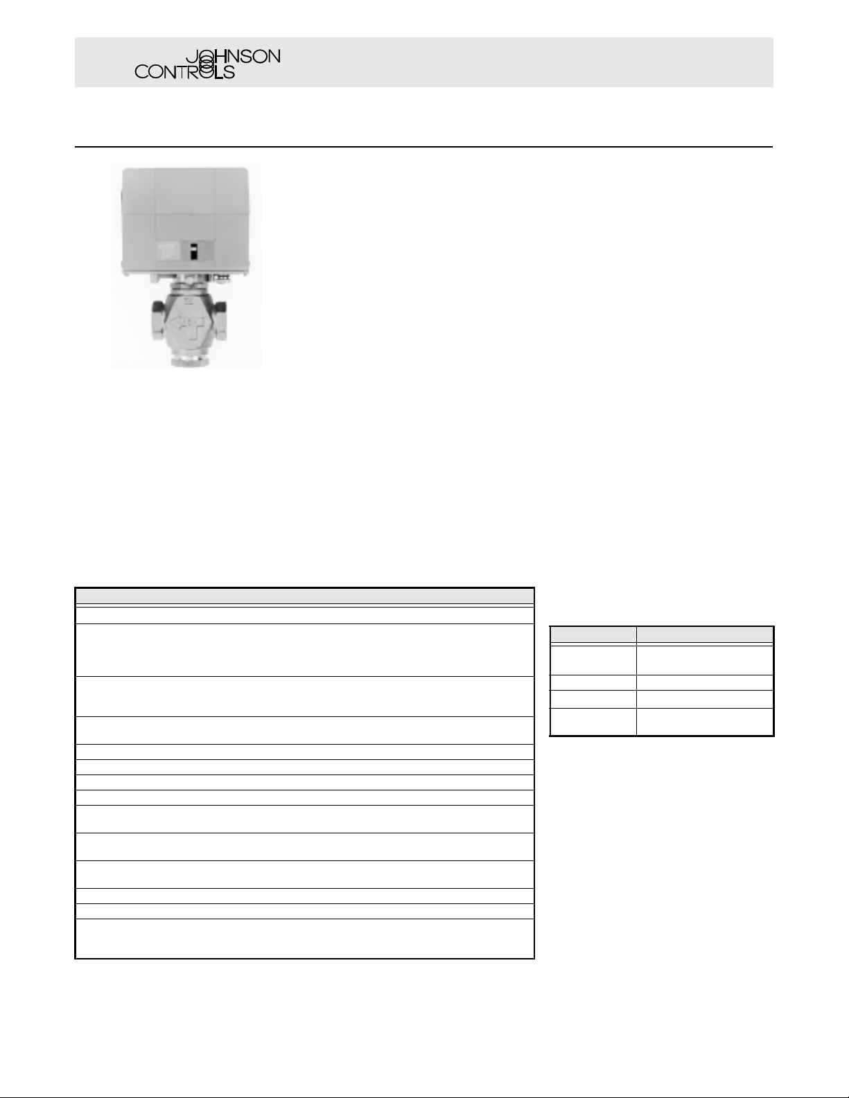
VA-8122-1 Valve Actuator
Description
The VA-8122 Proportional Valve Actu ator is
an electric actuator that provides proportional
contro l o f v alv es wit h up t o a 5/16 in . stro ke in
Heating, Ventilatin g, and Air Conditioning
(HVAC) applications. This compact, nonspring return actuator has a 22 lb minimum
seating force in a compact, easy-to-install
package.
decr ease installation costs
• selectable direction of action, Drive Down
or Drive Up, pro vi des appl ic at io n fl e xi bi lity
• wide range of control inputs meets the
needs of most applications
• power fail ur e detectio n an d low voltag e
indication prevent data corru ption of the
actuator's memory and warns of insufficient
suppl y voltage
• Light-Emitting Diode (LED) reduces
commis sionin g time and di splays op erati ng
status
Specifications
VA-8122 Proportional Valve Actuator
Power Requirements 24 VAC at 50/60 Hz, 5.0 VA supply minimum, Class 2
Jumper Selectable: 0 (2) to 10 VDC, 0 (4) to 20 VDC,
Input Signal
Input Impedance
5/16 in. Stroke Time
Force Shutoff and Breakaway: 22 lb (98 N) minimum
Cycles 60,000 full cycles; 1,500,000 repositions
Enclosure NEMA 1, IP20
Audible Noise Rating 35 dBA maximum at 3.28 ft (1 m)
Ambient Operating Conditions
Ambient Storage Conditions
Valve Media Temperature
Dimensions (H x W x D) 4.5 x 5.0 x 2.5 in. (114 x 127 x 64 mm)
Shipping Weig ht 1.6 lb (0.74 kg)
Agency Compliance
Factory Setting: 0 to 10 VDC,
Voltage Input: 0 to 10 VDC, 150,000 ohms and
Current Input: 0 to 20 mA, 500 ohms
50 Hz: Approximately 108 seconds nominal
60 Hz: Approximately 90 seconds nominal
35 to 135°F (2 to 57°C); 85°F (30°C)
Maximum dew point at 90% RH, non-condensing
-40 to 150°F (-40 to 65°C); 85°F (30°C)
Maximum dew point at 90% RH, non-condensing
Water: 195°F (90°C) maximum
Steam: Actuator is not rated for this application.
UL 873 Recognized, File E27734, Guide XAPX2
CSA C22.2 No. 139 Certified, File LR85083, Class 3221 02
CE Directive 89/336/EEC
6 (12) to 9 (18) VDC,0 (4) to 20 mA
Drive Down (DD) action on signal increase
0 to 20 VDC, 450,000 ohms
Applications
The actuator uses a reversible synchronous
motor to accurately position the valve. The
motor can reliab ly generate 22 pounds of
force in either the Drive Down or Drive Up
direction. Once the valve close s , a shutoff
force builds up. When this force reaches 22
pounds, a le ve r wit hin th e a ct uat or ope ra tes a
force sensor that stops the motor. The
constan t load at t he end of trav el en sure s tight
valve sea t shutoff a nd compensates for seat
wear.
Field ca libr a tion o f sh utof f i s n ot r e qu ire d. The
actuator mainta ins the shu toff force and its
last pos ition even if power is remove d.
Note: The valve stem can be positioned
manually by turning the manual
adjustment knob. Rotating the
knob counterclockwise moves the
valve st em up.
Repair Parts
Field repairs must not be made.
To Order
To order a p ropor ti onal valv e actu ator , c ontact
the near est Johnson Cont rols representative
and spe cif y pr o du ct co de nu mb er
Refer to the
Accessories
chart fo r acce ssorie s
VA-8122-1
availa ble.
Accessories
Code Number Description
VA-8020-100
VA-8020-601 Replacement cover only
VA-8020-605
M9000-105
(a) One kit is included with the actuator. If ordered
separately, it must be ordered in multiples of
five.
Mounting kit for VT Series
valves
(a)
Stem retainer and clip kit
Pluggable 3-position terminal
block
.
The performance specifications are nominal and conform to acceptable industry standards. For applications at conditions beyond these specifications, consult the local Johnson
Controls office. Johnson Controls, Inc. shall not be liable for damages resulting from misapplication or misuse of its products.
1/1
© 08/00 Johnson Controls, Inc
 Loading...