

Page 1
Valve and Actuator Manual 977
Actuators and Positioners Product Information Section
Technical Bulletin VA-8052
Issue Date 0489
VA-8052 Electric Valve Actuator
Installation & Calibration
The VA-8052-1 motor-driven
actuator provides proportional
control of valves with up to
3/4 in. lift in heating, ventilating,
and air conditioning
applications. This non-spring
return actuator has a 50 lb force
and requires a two-wire, voltage
signal (usually 0 to 10 VDC)
from the controller, and 24 VAC
power.
Installation
!
WARNING: Equipment
Damage Hazard. Do not
drive the VA-8052 actuator
unless it is mounted to a
valve. This can result in
permanent damage to the
actuator.
Installation of VA-8052-1 on
1/4 in. and 1/2 in. Stroke Valves
1. Unpack the VA-8052
Actuator and insure that the
feedback potentiometer
plunger is on top of the
coupler arm.
2. Install the valve packing
that is provided according
to the instructions included
with it.
3. Thread the 1/4 in. Palnut,
open side down, all the way
onto the valve stem.
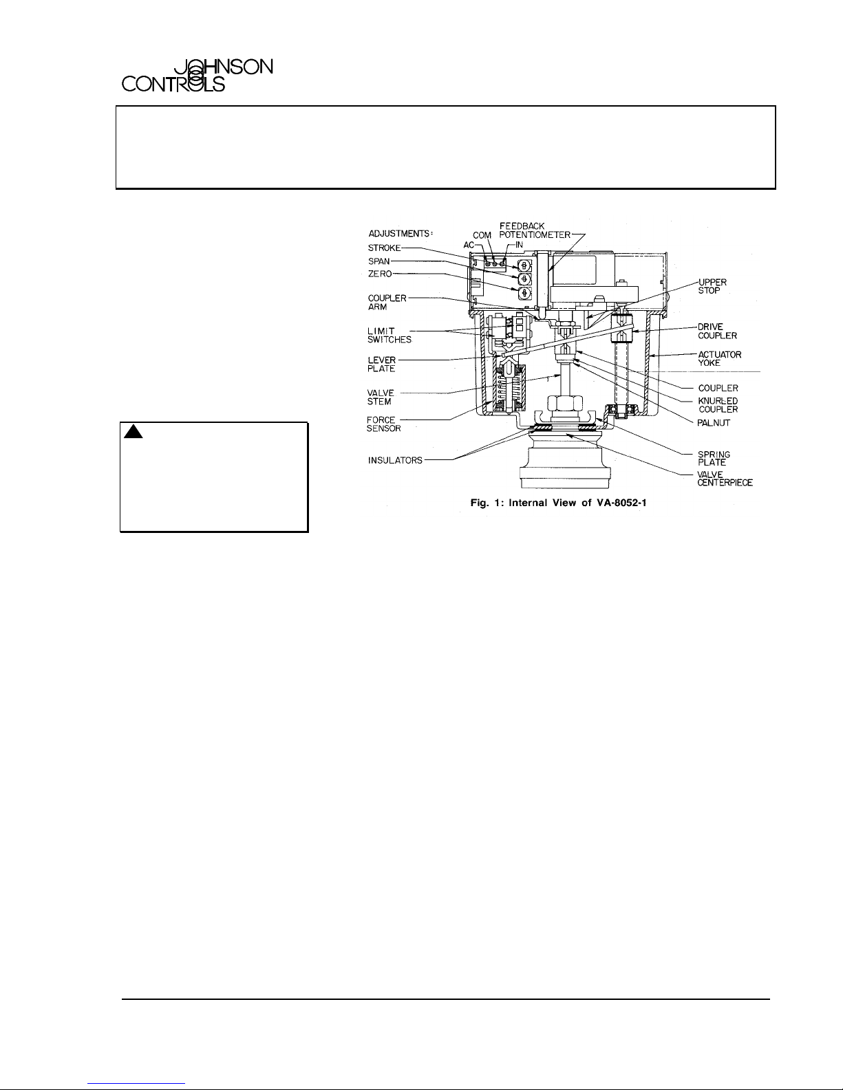
4. Loosely install the actuator
by sliding the actuator yoke
between the spring plate
and valve centerpiece
surface. Finger tighten the
spring plate to hold the
actuator in place (see
Fig. 1).
5. Obtain a source of 24 VAC
power and wire to the AC
and COM terminals. Wire a
source of 0 to 10 VDC to
the IN and COM terminals
(see Fig. 4). Check to see
© 1989 Johnson Controls, Inc. 1
Part No. 14-761-0, Rev. -Code No. LIT-977310x
that the stroke
potentiometer is fully CCW
(see Fig. 1).
6. Thread the knurled coupler
onto the valve stem until
approximately 1/4 in. of
thread remains between the
knurled coupler and the
Palnut. Note: It may be
necessary to pull the valve
stem up to meet the coupler
or to apply 0 to 10 VDC to
position the coupler above
the valve stem.
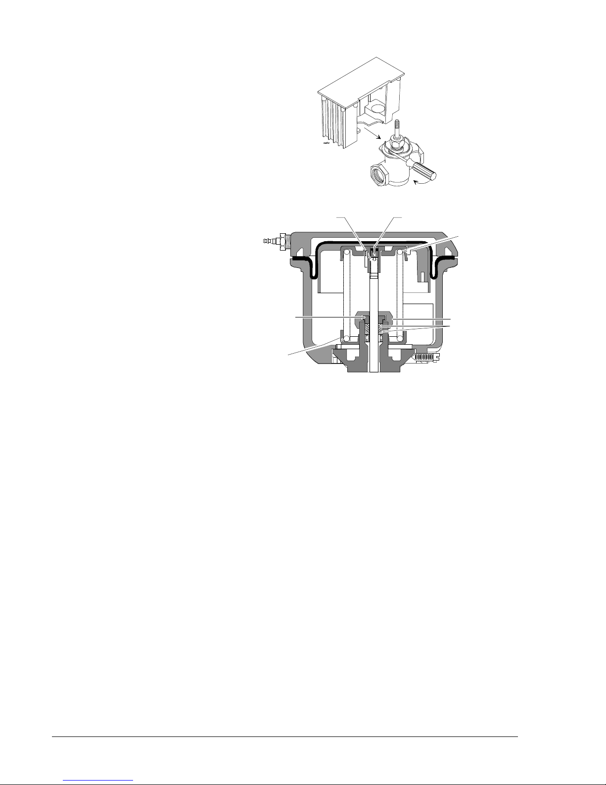
7. Secure the actuator in place
by tightening the spring
plate with a large
screwdriver (see Fig. 2).
8. Stroke the actuator to the
stem-up position by
applying 0 VDC. Thread
the knurled coupler onto the
valve stem until the knurled
coupler fits snugly.
9. Increase the signal slightly
(to 3 to 4 VDC) so that tension
on the coupler is relieved.
When lever stops moving,
thread the knurled coupler
on another 1 to 1-1/4 turn.
10. Reduce the signal to zero to
stroke the actuator to the
stem-up position. The limit
switch should click softly at
the full stem-up position. If
not, repeat step 9.
11. With the valve driven fully
up, thread the Palnut up the
stem until it contacts the
coupler. Tighten the Palnut
with a 7/16 in. wrench while
holding the nut on top of the
coupler with a 1/2 in.
wrench.
12. Provide an input signal of
10 VDC to the actuator.
After the actuator strokes
completely to the stemdown position, slowly adjust
the stroke potentiometer
CW until the stem just
begins to move up. Then
adjust the stroke
potentiometer CCW until
the stem strokes down and
the limit switch clicks. Turn
the stroke adjustment an
additional 1/8 rotation CCW
to assure positive full
stroke.
Page 2
13. Drive the actuator fully up
and down at least three
complete cycles (by
alternately applying 0 and
10 VDC), checking to see
that the upper and lower
limit switches click. Note:
The lever plate must not
contact the upper stop and
the drive coupler must not
contact the bottom surface
of the actuator yoke (see
Fig. 1).
Installation of VA-8052-1 on
3/4 in. Stroke, 2-Way Push
Down to Open (PDO) Valves
1 . Unpack the VA-8052
Actuator and insure that the
feedback potentiometer
plunger is on top of the
coupler arm.
2. Install the valve packing
that is provided according
to the instructions included
with it.
3. Thread the 1/4 in. Palnut,
open side down, onto the
valve stem and all the way
to the end of the threads.
4. Loosely install the actuator
by sliding the actuator yoke
between the spring plate
and valve centerpiece
surface. Finger tighten the
spring plate to hold the
actuator in place (see
Fig. 1).
5. Obtain a source of 24 VAC
power and wire to the AC
and COM terminals (see
Fig. 4). Wire a source of 0
to 10 VDC to the IN and
COM terminals. Check to
see that the stroke
potentiometer is fully CCW
(see Fig. 1).
6. Thread the knurled coupler
onto the valve stem until
approximately 1/4 in. of
thread remains between the
knurled coupler and the
Palnut. Note: It may be
necessary to pull the valve
stem up to meet the coupler
or to apply 0 to 10 VDC to
position the coupler above
the valve stem.
Fig. 2: Isometric Drawing of VA-8052
Fig. 3: Internal View of V-3000 Actuator
7. Secure the actuator in place
by tightening the spring
plate with a large
screwdriver (see Fig. 2).
8. Stroke the actuator to the
stem-up position by
applying 0 VDC. Thread
the knurled coupler onto the
valve stem until the knurled
coupler fits snugly.
9. Increase the signal slightly
(to 3 to 4 VDC) so that
tension on the knurled
coupler is relieved. When
the lever stops moving,
thread the knurled coupler
on another 1 to 1-1/4 turn.
10. Reduce the signal to zero to
stroke the actuator to the
stem-up position. The limit
switch should click softly at
the full stem-up position. If
not, repeat step 9.
11. With the valve driven fully
up, thread the Palnut up the
stem until it contacts the
coupler. Tighten the Palnut
with a 7/16 in. wrench while
holding the nut on top of the
coupler with a 1/2 in. wrench.
12. Drive the actuator fully up
and down at least three
complete cycles, (by
alternately applying 0 and
10 VDC) checking to see
that the upper limit switch
clicks. Note: The lever
2 VA-8052 Technical Bulletin
Page 3

plate must not contact the
upper stop and the drive
coupler must not contact
the bottom surface of the
actuator yoke (see Fig. 1).
Installation of VA-8052-1 on
3/4 in. Stroke 2-Way, Push
Down to Close (PDC) Valves
1. Unpack the VA-8052
Actuator and insure that the
feedback potentiometer
plunger is on top of the
coupler arm.
2. Install the valve packing
that is provided according
to the instructions included
with it.
3. Thread the 1/4 in. Palnut,
open side down, onto the
valve stem and all the way
to the end of the threads.
4. Loosely install the actuator
by sliding the actuator yoke
between the spring plate
and valve centerpiece
surface. Finger tighten the
spring plate to hold the
actuator in place (see Fig. 1).
VA-8052 Technical Bulletin 3
Page 4

5. Obtain a source of 24 VAC
power and wire to the AC
and COM terminals. Wire a
source of 0 to 10 VDC to
the IN and COM terminals
(see Fig. 4). Check to see
that the stroke potentiometer is
fully CCW (see Fig. 1).
6. Thread the knurled coupler
onto the valve stem until
approximately 1/8 in. of
thread remains between the
knurled coupler and the
Palnut. Note: It may be
necessary to pull the valve
stem up to meet the coupler
or to apply 0 to 10 VDC to
position the coupler above the
valve stem.
7. Secure the actuator in place
by tightening the spring
plate with a large
screwdriver (see Fig. 2).
8. Stroke the actuator to the
stem-down position by
applying 10 VDC. Unthread
the knurled coupler CCW
on the valve stem until the
knurled coupler fits snugly.
9. Decrease the signal slightly
(to 6 to 7 VDC) so that
compression on the coupler
is relieved. When the lever
stops moving, unthread the
knurled coupler another 2 to
3 turns.
10. Increase the signal to
10 VDC to stroke the
actuator to the stem-down
position. The limit switch
should click at the full stemdown position. If the switch
does not click, repeat
step 9.
11. With the valve driven fully
down, thread the Palnut up
the stem until it contacts the
coupler. Tighten the Palnut
with a 7/16 in. wrench while
holding the nut on top of the
coupler with a 1/2 in.
wrench.
12. Drive the actuator fully up
and down at least three
complete cycles, checking
to see that the lower limit
switch clicks. Note: The
lever plate must not contact
the upper stop and the drive
coupler must not contact
the bottom surface of the
actuator yoke (see Fig. 1).
Retrofit
To remove the V-3000 actuator,
upper spring plate, and spring,
refer to Fig. 3 and proceed as
follows:
1. Disconnect the air line to
the actuator.
2. Remove the actuator by
loosening the actuator set
screw on the bottom of the
lower diaphragm case. Lift
the actuator off of the valve.
3. Hold the stem extension
firmly with a 9/16 in. boxhead wrench and, with a
small screw driver, loosen
the stem locking screw.
4. For V-3000 Series Valves,
compress the spring using
the JC 5389 Spring
Compression Tool. For
V-3800 Series Valves,
compress the spring with
hand pressure.
5. Using a 9/16 in. box-head
wrench, unscrew the stem
extension. Lift the spring
and upper spring plate off of
the valve. Remove the spring
compression tool if used.
6. Thread the lower spring
plate up the centerpiece
stuffing box to increase
spacing between the spring
plate and the valve centerpiece mounting surface.
Calibration
Calibration for 1/4 to 1/2 in.
Stroke Valves
The stroke, zero, and span
settings are factory calibrated to
accept a 0 to 10 volt signal from
a controller. To change the
factory settings, proceed as
follows:
Stroke Adjustment ( See Fig. 1)
1. Adjust the stroke
potentiometer fully CCW to
maximum. Adjust the span
potentiometer fully CCW to
minimum. Adjust the zero
potentiometer fully CW to
minimum.
2. Provide an input signal of
10 VDC to the actuator.
After the actuator strokes
completely to the stemdown position, slowly adjust
the stroke potentiometer
CW until the stem just
begins to move up. Then
adjust the stroke
potentiometer CCW until
the stem strokes down and
the limit switch clicks. Turn
the stroke adjustment an
additional 1/8 rotation CCW
to assure positive full
stroke.
Zero Adjustment
3. Adjust the zero
potentiometer fully CCW to
maximum.
4. Provide an input signal
equal to the desired zero
(starting point) value and
then wait for the actuator to
stroke to the stem-up
position and the limit switch
clicks.
5. Slowly adjust the zero
potentiometer CW until the
actuator just begins to
stroke.
Span Adjustment
6. Adjust the span
potentiometer fully CW to
maximum.
7. Provide an input signal
equal to the desired full
stroke voltage. (This value
must be at least 2.5 VDC
greater than the zero value.)
8. Slowly adjust the span
potentiometer CCW until
the actuator is fully stroked
to the stem-down position
and the limit switch clicks.
Calibration for 3/4 in. Stroke,
2-Way PDO Valves
The stroke, zero, and span
settings are factory calibrated to
accept a 0 to 10 volt signal from
4 VA-8052 Technical Bulletin
Page 5

a controller. To change the
factory settings, proceed as
follows:
Stroke Adjustment (See Fig. 1)
1. Adjust the stroke
potentiometer fully CCW to
maximum. Adjust the span
potentiometer fully CCW to
minimum.
Zero Adjustment
2. Adjust the zero potentiometer
fully CCW to maximum.
3. Provide an input signal
equal to the desired zero
(starting point) value and
then wait for the actuator to
stroke to the stem-up position
and the limit switch clicks.
4. Slowly adjust the zero
potentiometer CW until the
actuator just begins to stroke.
Span Adjustment
5. Adjust the span potentiometer
fully CW to maximum.
6. Provide an input signal
equal to the desired full
stroke voltage. (This value
7. Slowly adjust the span
potentiometer CCW until
the actuator is fully stroked
to the stem-down position.
The drive coupler must not
contact the bottom surface
of the actuator yoke.
Calibration for 3/4 in. Stroke,
2-Way PDC Valves
The stroke, zero and span
settings are factory calibrated to
accept a 0 to 10 VDC from a
controller. To change the
factory settings, proceed as
follows:
Stroke Adjustment (See Fig. 1)
1. Adjust the stroke
potentiometer fully CCW to
maximum. Adjust the span
potentiometer fully CCW to
minimum.
Zero Adjustment
2. Adjust the zero
potentiometer fully CCW to
maximum.
3. Provide an input signal
equal to the desired zero
(starting point) value and
then wait for the actuator to
stroke to the stem-up
position.
4. Slowly adjust the zero
potentiometer CW until
the actuator just begins to
stroke.
Span Adjustment
5. Adjust the span
potentiometer fully CW to
maximum.
6. Provide an input signal
equal to the desired full
stroke voltage. (This value
must be at least 2.5 VDC
greater than the zero value.)
7. Slowly adjust the span
potentiometer CCW until
the actuator is fully stroked
to the stem-down position
and the limit switch clicks.
Wiring
All wiring must be in accordance
with applicable electrical code
requirements. Input lines to the
actuator must be wired correctly
for the valve to work.
!
CAUTION: Use the
VA-8000-101 Insulator Kit
for steam applications,
280°F (138°C) maximum.
Repair Information
Field repairs must not be made.
For a replacement VA-8052,
contact the nearest Johnson
Controls branch office.
Application and Drawing
Identification
Fig. 4 -- Typical Application
must be at least 2.5
VDC greater than the
zero value.)
Controls Group
507 E. Michigan Street
P.O. Box 423 Printed in U.S.A.
Milwaukee, WI 53202
Fig. 5 -- VA-8052 Dimensions in./mm
VA-8052 Technical Bulletin 5
 Loading...