

Johnson Controls VA78*0-HG*-2 Series, VA7810-HG*-2 Series, VA7830-HG*-2 Series, VA7810-AD*-2 Series, VA7810-AG*-2 Series Product Bulletin
...Page 1
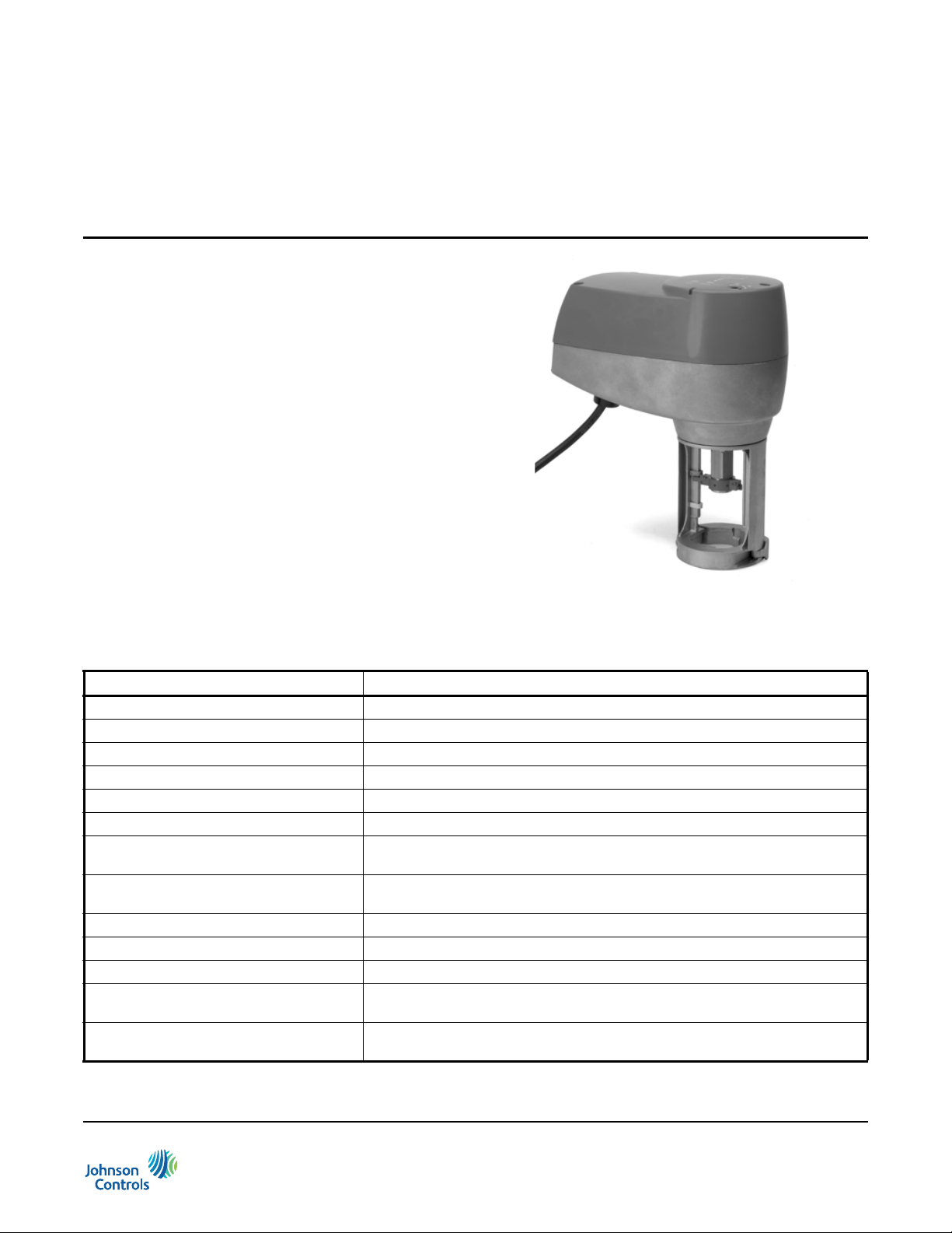
Figure 1: VA7800 Actuator
VA7800 Series Electric Valve Actuators
Product Bulletin
VA7800 Series
Refer to the QuickLIT website for the most up-to-date version of this document.
The VA7800 Series of Electric Valve Actuators control
VG7000 Series Bronze Globe Valves in Heating,
Ventilating, an d Air Conditioning (HVAC) systems. The
V A7800 Series produces a minimum linea r output force
of 180 lb (800 N) and is ordered field mounted or
factory coupled to 1 in. and 2 in. VG7000 Series
Bronze Globe Valves with brass trim and to 1/2 in.
through 2in. VG7000 Series Bronze Globe Valves with
stainless steel trim. All actuators are direct mount and
available in both Spring Return and Non-Spri ng Return
models.
Spring Return models ship from the factory set for
DC 0 to 10 V Proportional Control. With a change of
DIP switch settings, this model can be field configured
to On/Off or Floating Control. In addition to these
settings, optional auxiliary switches are also available.
Code No. LIT-12011474
Issued June 2018
Non-Spring Return models are available in AC 24 V
On/Off (Floating) Control, or DC 0 to 10 V Proportional
Control. Models are available with or without optional
auxiliary switches.
Table 1: Features and Benefits
Features Benefits
Automatic Stroke Adjustment Provides easy, quick, and precise commissioning.
Manual Override as Standard Allows manual positioning of valve for easy commissioning and servicing.
NEMA 2 (IP54) Enclosure Protection Allows installation in a wide range of environments.
Unique Swing-Gate Yoke Offers fast and secure attachment to the valve.
Brushless Motor Ensures low energy consumption and long life.
Proportional Model Enables one model to be used for various control types.
Force-Controlled Motor Shut-Off Reduces energy consumption, wear of the actuator, and protects the valve from
excessive forces.
Stroke Position Indicator Gives visual indication of valve operation, provides automatic adjustment of
Status Light-Emitting Diode (LED) Gives visual indication of actuator status and assists with diagnostic.
Optional Integrated Auxiliary Switches Provides adjustable switch points with line voltage capability.
Integral Cable with Colored Conductors Simplifies installation and field wiring.
Integral Connector for 3/8 in. (10 mm)
Flexible Metal Conduit (FMC)
Underwriters Laboratories Inc.® (UL)
and CE Compliant
stroke indicators during first cycle of operation.
Simplifies installation and field wiring.
Provides internationally recognized regulatory agency approval.
VA7800 Series Electric Valve Actuators Product Bulletin
1
Page 2

Application Overview
IMPORTANT: The VA7800 Series Electric Valve
Actuators are intended to control saturated steam,
hot water, and chilled water flow under normal
equipment operating conditions. Where failure or
malfunction of the VA7800 Series Valve Actuator
could lead to personal injury or property damage to
the controlled equipment or other property,
additional precautions must be designed into the
control system. Incorporate and maintain other
devices, such as supervisory or alarm systems or
safety or limit controls, intended to warn o f or protect
against failure or malfunction of the VA7800 Series
V alve Actuator .
VA7810-Axx-2 Series Non-Spring Return On/ Off and Floating Point Actuator
The VA7810-AGx-2 Series Non-Spring Return
Actuators provide fail-in-place on/off or modulating
control of valves in HVAC systems. On/Off Control is
provided from a manual switch, an auxiliary switch from
a pump contactor, or a similar device. Floating Point
Control is provided from a triac or relay.
VA7810-HGx-2 Series Non-Spring Return Proportional Actuator
The VA7810-HGx-2 Series Non-Spring Return
Actuators offer fail-in-place proportional control of
valves in HVAC systems regulated by an electronic
controller . These a ctuators are configured for response
to 0 to 10 VDC, 2 to 10 VDC, 0 to 20 mA, or 4 to 20 mA.
The VA7810-HGx-2 Series can also be custom
configured for valve sequencing. The minimum setpo int
is 0 to 6 VDC (0 to 12 mA), and maximum input signal
is 3 to 10 VDC (6 to 20 mA). A
0 to 10 VDC, or 2 to 10 VDC feedback signal is
available for position indication. The actuator features a
preset actuator position with a stem that extends or
retracts on loss of signal. However, when you select
current input, this stem feature is not available.
VA7820-HGx-2/VA7830-HGx-2 Series Spring Return Proportional Actuator
The VA7820-HGx-2 and VA7830-HGx-2 Series
Actuators are Spring Return actuators that provide
fail-safe proportional control of valves in HV AC systems
regulated by an electronic controller. In the event of
power loss, the V A7820 -HGx-2 Series Actuators spring
return with the actuator stem fully retracted and the
valve stem in the full up position. On loss of power, the
VA7830-HGx-2 Series Actuators spring return with the
actuator stem fully extended and the valve stem in the
full down position.
These actuators are configured for response to 0 to
10 VDC, 2 to 10 VDC, 0 to 20 mA, or 4 to 20 mA. Both
models of actuators can also be custom configured for
valve sequencing. Minimum setpoint is 0 to 6 VDC (0 to
12 mA) and maximum input signal is 3 to 10 VDC (6 to
20 mA). A 0 to 10, or 2 to 10 VDC feedback signal is
available for position indication. The actuator s feature a
preset actuator position with a stem that extends or
retracts, on loss of signal. When current input is
selected, this stem feature is not available.
Operation
The VA7800 Series of actuators offers up to 1 in.
(25 mm) of linear stroke for the operation of
Johnson Controls® VG7000 Series Bronze Control
Valves. The actuators interface to all threaded stem
VG7000 Valves
trim VG7000 series valves from 1/2 in. to 2 in. The
actuator should not be used on brass trim VG7000
series valves from 1/2 in. to 3/4 in.
be manually positioned by means of a 5 mm Allen
wrench.
For non-spring return actuators, engage manual
operation by inserting the Allen wrench into the
hexagonal socket and pushing down to cut off the
power to the motor. Turn the Allen wrench clockwise to
extend the actuator stem; turn the wrench
counterclockwise to retract the actuator stem.
For spring return actuators, manual operation requires
that the power be disconnected. On loss of power, the
actuator spring force moves the stem to its fail-safe
position. For manual operation, insert the Allen wrench
into the hexagonal socket and turn the wrench either
clockwise or counterclockwise depending on the
actuator model. When you reach the desired stem
position, push the wrench down and slightly rotate the
wrench in the opposite direction to lock it in position.
When power resumes, the actuator is released from its
manual position.
Note: After using manual control to position the
actuator, it is recommended that a self-calibration cycle
be performed to assure proper operation.
VA7810-AGx-2 Series Non-Spring Return On/ Off and Floating Point Actuator
The VA7810-AGx-2 Series Non-Spring Return
Actuators are offered with On/Off Control or Floating
Control. Select these controls by applying power to
different terminals located on the actuator. For a more
detailed procedure, refer to the appropriate installation
instructions for the actuator.
and can be used on all stainless steel
All actuators can
VA7800 Series Electric Valve Actuators Product Bulletin
2
Page 3
For On/Off Control, apply power continuously to
Terminal 1 (Common) and Terminal 2 (Power). From
this action, the actuator assumes its fully extended
stem position. To fully retract the stem, apply power
through the controlling device to Terminal 3. When
power is removed from Terminal 3, the actuator returns
to its fully extended position. In the event of power loss,
the actuator remains in its last position.
To enable Floating Control, wire Terminal 1 to the
common. Apply power to Terminal 2 to extend the
actuator stem, or to Terminal 3 to retract the actuator
stem. If power is removed from Terminal 2 and
Terminal 3, or in the event of complete power loss, the
actuator remains in its last position.
VA78x0-HGx-2 Series Proportional Control Actuators
The VA78x0-HGx Series Actuators operate with
Proportional Control, On/Off Control, or Floating
Control. Changes in DIP switch settings allow the
selection of Control Type, Input Signal, Input Range,
Action, actuator position at signal loss, and stroke
speed. See Table 2 for a detailed reference of DIP
switch settings.
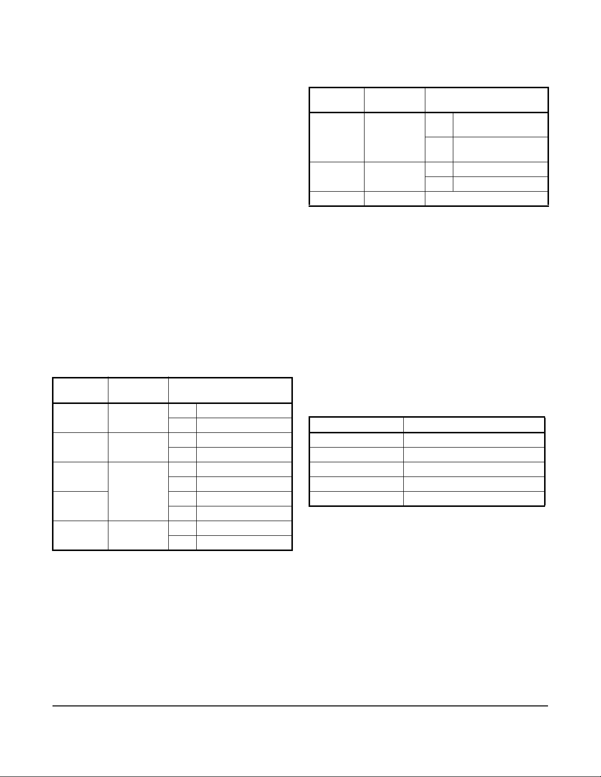
Table 2: VA78x0-HGx-2 Series Proportional
Control Actuators DIP Switch Settings
(Part 1 of 2)
DIP Switch
Number
1 Control Type ON Floating/on/off control
2 Input Signal ON Current input signal
3 Input Signal
4 ON 2 to 10 V (4 to 20 mA)
5 Action ON Reverse
Description State
OFF Proportional control
OFF Voltage input signal
ON Custom setting
Range
OFF Pre-defined setti ng
OFF 0 to 10 V (0 to 20 mA)
OFF Direct
Table 2: VA78x0-HGx-2 Series Proportional
Control Actuators DIP Switch Settings
(Part 2 of 2)
DIP Switch
Number
6 Preset
7 Stroke
8 Not Used Not Used
1. Control signal loss position preset does not operate when
you select 0 to 20 mA or custom input range control.
Description State
ON Actuator Stem
Actuator
Position at
Signal Loss
Speed
OFF Actuator Stem
1
ON 76 s/in. (3 s/mm)
OFF 152 s/in. (6 s/mm)
Extends
Retracts
The VA78x0-HGx Series Actuators are a direct acting
and factory supplied set for 0 to 10 VDC Proportional
Control. Field setting options exist for standard ranges
of 0 to 20 VDC (0 to 20 mA) or 2 to 10 VDC (4 to
20 mA) control in the field. At the end of a span, the
actuator control signal has a buffer zone of 0.3 V
(0.6 mA) to ensure definite valve close-off.
You can set the actuators for custom signal ranges.
Minimum setpoint is 0 to 6 VDC (0 to 12 mA) and
maximum input signal is 3 to 10 VDC (6 to 20 mA).
Position feedback signal is also available in Table 3.
Table 3: Position Feedback Signal for
VA78x0-HGx-2 Series Proportional
Control Actuators
Input Signal Feedback Output
0 to 10 VDC 0 to 10 VDC
2 to 10 VDC 2 to 10 VDC
0 to 20 mA 0 to 10 VDC
4 to 20 mA 2 to 10 VDC
Custom Range 0 to 10 VDC
VA7800 Series Electric Valve Actuators Product Bulletin
3
Page 4
All VA78x0-HGx-2 Series Actuators feature a
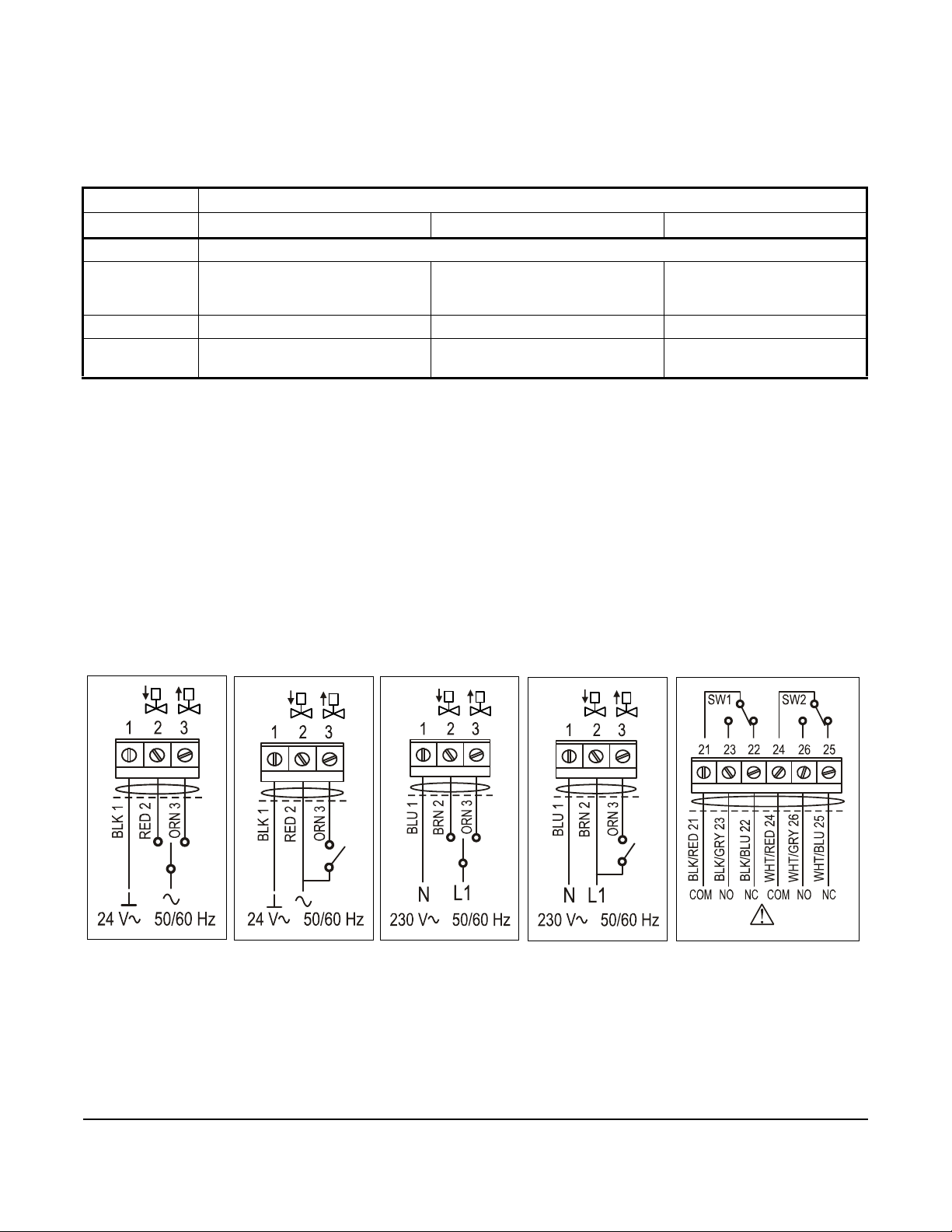
Figure 2: VA7810-Axx-2 Wiring Diagram
VA7810-AGx-2 Wired
as Floating
VA7810-AGx-2 Wired
as OPEN/CLOSE
VA7810-ADx-2 Wired
as Floating
VA7810-ADx-2 Wired
as OPEN/CLOSE
VA7810-AxC-2
Auxiliary Switches Wiring
multicolored LED that provides operational status and
failure analysis information. See Table 4 for a detailed
description of LED color indicators.
Table 4: VA78x0-HGx-2 Series Actuators LED Status and Color Indicators
LED Color
Status Green Yellow Red
Off Power off
Blink Motor running Power on after a black-out
Temporary fault, possible valve
2
sticking
Fast Blink Calibrating Input signal failure
Continuous
On
1. After re aching both ends of the stroke, the input signal is recalibrated and the LED switches to green.
2. The actuato r leaves this mode only if the push button is pressed for at least 5 seconds, and the previously detected error
has been resolved.
3. This status is temporary. When the detected temperature decreases to the acceptable range, the LED switches back to
green.
Power on, motor not running Custom calibration value out of
range
1
High temperature
Generic fault
3
The actuator microprocessor carries out a failure
diagnosis when a failure has been detected. The
colored LED indicates the actuator status. When the
microprocessor dete cts that the stem has come to an
unexpected stop, it initiates a retry cycle. The retry
cycle repeats three times, and if unsuccessful, the
actuator switches to fault mode and the LED flashes
yellow. If the problem is cleare d, the actuator continu es
to function normally.
The LED also flashes yellow when power resumes
after a power loss. The LED continues to flash yellow
until the end stop is achieved or a recalibration process
is manually started.
Wiring Diagrams
Figure 2 and Figure 3 show detailed diagrams for the
wiring configurations of the VA7800 Series Electric
Valve Actuators.
VA7800 Series Electric Valve Actuators Product Bulletin
4
FIG:W IR10_a xx
Page 5

Mounting
Figure 3: VA78x0-HGx-2 Wiring Diagram
Figure 4: VG7800 Mounting
When mounting the actuator on a valve, the following
precautions are recommended:
• Never cover the actuator with insulating material.
• Allow sufficient clearance to remove the actuator.
• Mount the valve in an upright angle or at an angle
less than 90° from the vertical for fluid
temperatures up to 212°F (100°C).
• Orient the actuator so that the yoke supports are
one above the other when mounting the valve
horizontally.
• Install the valve with the stem horizontal and
insulate the pipe to minimize heat transfer to the
actuator for fluid temperatures above 212°F
(100°C).
FIG:MT_7800
VA7800 Series Electric Valve Actuators Product Bulletin
5
Page 6

Ordering Information
Contact the nearest Johnson Controls representative
and specify the desired product code number from
Table 5.
Table 5: VA-78x0-xxx-2 Series Electric Valve Actuators
Code Number Input Signal Power
On/Off
Floating Point
VA7810-ADC-2
VA7810-AGA-2
VA7810-AGC-2
VA7810-HGA-2
VA7810-HGC-2
VA7820-HGA-2
VA7820-HGC-2
VA7830-HGA-2
VA7830-HGC-2
X X --- --- X 8 X --- --- --- X 48 76 114
X X --- X --- 3 X --- --- --- --- 48 76 114
X X --- X --- 3 X --- --- --- X 48 76 114
X X X X --- 6 X --- --- X --- 24/48 38/76 57/114
X X X X --- 6 X --- --- X X 24/48 38/76 57/114
X X X X --- 11 --- X --- X --- 24/48 38/76 57/114
X X X X --- 11 --- X --- X X 24/48 38/76 57/114
X X X X --- 11 --- --- X X --- 24/48 38/76 57/114
X X X X --- 11 --- --- X X X 24/48 38/76 57/114
Proportional 0 (2) to 10 VDC
0 (4) to 20 mA
Requirements
24 VAC 50/60 Hz ± 15%
230 VAC 50/60 Hz ± 15%
Action on Power
Failure
VA Rating
Non-Spring Return
Spring Return Actuator
Retracted Va lve Ste m F ull Up
Feedback Auxiliary
Spring Return Actuator
Extended Valve Stem Full Down
0 (2) to 10 VDC
Switches
2 SPDT, 1A, 3A Resis tive,
1/4 HP
Nominal Stroke Time
(Seconds)
1/2 and 3/4 in. VG7000
(5/16 in. valve stroke)
1 and 1-1/4 in. VG7000
(1/2 in. valve stroke)
1
1-1/2 and 2 in. VG7000
(3/4 in. valve stroke)
1. VA 78 x0-HGx-2 actuators have field selectable stroke spee d ; fact or y setting is the slowest speed.
Repair Information
If a V A78x0-xxx-2 Seri es Electric Valve Actuator fails to
operate within specifications, replace th e un it. F or a
replacement actuator, contact the nearest
Johnson Controls representative.
Table 6: Accessories Ordering Information
Product Code Number Description
V-9999-BC1 Mounting Kit to Mount VA-715x, VA-720x, VA78xx, or VA-4233 Series Electric Actuators
to Barber Coleman® 1/2 through 1-1/4 Inch VB-9xxx Valve Bodies
V-9999-HW1 Mounting Kit to Mount VA-715x, VA-720x, VA78xx, or VA-4233 Series Electric Actuators
to Honeywell® V5011A, F, and G, 1/2 through 3 Inch Single-Seated and V5013F
Three-Way Valves
VA7800 Series Electric Valve Actuators Product Bulletin
6
Page 7

Dimensions
Figure 5: Dimensions, in. (mm)
8.35 (212
)
4.56 (116)
9.6 (244)
5.9 Minimum(150)
VA7800 Series Electric Valve Actuators Product Bulletin
7
Page 8

Technical Specifications
Table 7: VA7810-AGx-2 and VA7810-ADx-2 Series On/Off (Floating) Electric Non-Spring Return Valve
Actuators
Model VA7810-AGx-2 VA7810-ADx-2
Thrust Force 180 lb (800 N) minimum
Power Supply AC 24 V (AC 19 to 30 V) at 50/60 Hz,
Class 2
Transformer Sizing 3 VA 8 VA
Input Signal AC 24 V (AC 19 to 30 V) at 50/60 Hz AC 230 V (AC 195 to 265 V) at 50/60
Feedback N/A N/A
Auxiliary Switch Rating Two Single-Pole, Double-Throw (SPDT), AC 230 V, 3.0 A Resistive, 1/4 hp
Stroke 5/16 to 1 in. (8 to 25 mm)
Stroke Speed 5/16 in. stroke: 48 seconds
1/2 in. stroke: 76 seconds
3/4 in. stroke: 114 seconds
Ambient Operating Conditions 23 to 131°F (-5 to 55°C); 10 to 90% RH Noncondensing
Enclosure Rating NEMA 2 (IP54)
Electrical Connection 48 in. (1.2 m) UL 758 Type AWM Halogen Free Cable with 18 AWG
(0.85 mm
Dimensions 9.6 x 4.56 x 8.35 in. (244 x 116 x 212 mm)
Materials Gearbox and Yoke Die Cast Aluminum
Cover Resin ABS/PC - UL94-V0
Stem Stainless Steel
Coupler Brass
Life Cycles 100,000 full stroke cycles
Shipping Weight 5.4 lb (2.5 kg)
Compliance United States UL 60730 Listed Type 1 Enclosure, CCN XAPX, File E194024
Canada UL 60730-1 Listed Type 1 Enclosure, CCD XAPX7, File E194024
Europe CE Mark - Johnson Controls, Inc. declares that this product is in compliance
with the essential requirements and other relevant provisions of the
EMC directive and the Low Voltage Directive.
2
) Conductors and 0.25 in. (6 mm) Ferrule Ends
AC 230 V (AC 195 to 265 V) at 50/60
Hz
Hz
VA7800 Series Electric Valve Actuators Product Bulletin
8
Page 9

Table 8: VA7810-HGx-2 Series Proportional Electric Non-Spring Return Valve Actuators
Model VA7810-HGx-2
Thrust Force 180 lb (800 N) minimum
Power Supply AC 24 V (AC 19 to 30 V) at 50/60 Hz, Class 2
Transformer Sizing 6 VA
Input Signal Switch Selectable:
Proportional: DC 0 to 10 V, DC 2 to 10 V, 0 to 20 mA or 4 to 20 mA
Programmable Proportional:
Start Point: 0 to 6 VDC (0 to 12 mA)
End Point: 3 to 10 VDC (6 to 20 mA) with 3 VDC (6 mA) minimum span
On/Off (Floating): AC 24 V at 50/60 Hz
Switch Selectable Direct or Reverse Action with signal increase
Switch Selectable preset actuator position on loss of signal
Control Input Impedance Voltage Input: 100k ohm
Current Input: 120 ohm
Feedback DC 0 (2) to 10 V corresponds to input range
Auxiliary Switch Rating SPDT, AC 230 V, 3.0 A Resistive, 1/4 hp
Stroke 5/16 to 1 in. (8 to 25 mm)
Stroke Speed (Switch Selectable) Sl ow (Fa cto ry Setting) 5/16 in. stroke: 48 seconds
1/2 in. stroke: 76 seconds
3/4 in. stroke: 114 seconds
Fast 5/16 in. stroke: 24 seconds
1/2 in. stroke: 38 seconds
3/4 in. stroke: 57 seconds
Ambient Operating Conditions 23 to 131°F (-5 to 55°C); 10 to 90% RH Noncondensin g
Ambient Storage Conditions -40 to 176°F (-40 to 80°C); 5 to 95% RH Noncondensing
Enclosure Rating NEMA 2 (IP54)
Electrical Connection 48 in. (1.2 m) UL 758 Type AWM Halogen Free Cable with 18 AWG
(0.85 mm
Dimensions 9.6 x 4.56 x 8.35 in. (244 x 116 x 212 mm)
Materials Gearbox and Yoke Die Cast Aluminum
Cover Resin ABS/PC - UL94-V0
Stem Stainless Steel
Coupler Brass
Life Cycles 100,000 full stroke cycles
Shipping Weight 5.4 lb (2.5 kg)
Compliance United States UL 60730 Listed Type 1 Enclosure, CCN XAPX, File E194024
Canada UL 60730-1 Listed Type 1 Enclosure, CCN XAPX7, File E194024
Europe CE Mark - Johnson Controls, Inc. declares that this product is in compliance
with the essential requirements and other relevant provisions of the
EMC directive and the Low Voltage Directive.
2
) Conductors and 0.25 in (6 mm) Ferrule Ends
VA7800 Series Electric Valve Actuators Product Bulletin
9
Page 10

Table 9: VA7820-HGx-2 / VA7830-HGx-2 Series Proportional Electric Spring Return Valve Actuators
Model VA7820-HGx-2 / VA7830-HGx-2
Thrust Force 180 lb (800 N) minimum
Power Supply AC 24 V (AC 19 to 30 V) at 50/60 Hz, Class 2
Transformer Sizing 11 VA
Input Signal Switch Selectable:
Proportional: DC 0 to 10 V, DC 2 to 10 V, 0 to 20 mA or 4 to 20 mA
Programmable Proportional:
Start Point: 0 to 6 VDC (0 to 12 mA)
End Point: 3 to 10 VDC (6 to 20 mA) with a 3 VDC (6 mA) minimum span
On/Off (Floating): AC 24 V at 50/60 Hz
Switch Selectable Direct or Reverse Action with signal increase
Switch Selectable reset actuator position on loss of signal
Control Input Impedance Voltage Input: 100k ohm
Current Input: 120 ohm
Feedback DC 0 (2) to 10 V corresponds to input range
Auxiliary Switch Rating SPDT, AC 230 V, 3.0 A Resistive, 1/4 hp
Stroke 5/16 to 1 in. (8 to 25 mm)
Stroke Speed Slow (Factory Setting) 5/16 in. stroke: 48 seconds
1/2 in. stroke: 76 seconds
3/4 in. stroke: 114 seconds
Fast 5/16 in. stroke: 24 seconds
1/2 in. stroke: 38 seconds
3/4 in. stroke: 57 seconds
Ambient Operating Conditions 23 to 131°F (-5 to 55°C); 10 to 90% RH Noncondensing
Ambient Storage Conditions -40 to 176°F (-40 to 80°C); 5 to 95% RH Noncondensing
Enclosure Rating NEMA 2 (IP54)
Electrical Connection 48 in. (1.2 m) UL 758 Type AWM Halogen Free Cable with 18 AWG
(0.85 mm
Dimensions 9.6 x 4.56 x 8.35 in. (244 x 116 x 212 mm)
Materials Gearbox and Yoke Die Cast Aluminum
Cover Resin ABS/PC - UL94-V0
Stem Stainless Steel
Coupler Brass
Life Cycles 100,000 full stroke cycles
Shipping Weight 7.3 lb (3.3 kg)
Compliance United States UL 60730 Listed Type 1 Enclosure, CCN XAPX, File E194024
Canada UL 60730-1 Listed Type 1 Enclosure, CCN XAPX7, File E194024
Europe CE Mark - Johnson Controls, Inc. declares that this product is in compliance
with the essential requirements and other relevant provisions of the
EMC directive and the Low Voltage Directive.
2
) Conductors and 0.25 in. (6 mm) Ferrule Ends
The performance specifications are nominal and conform to acceptable industry standards. For application at conditions beyond these
specifications, consult the local Johnson Controls office. Johnson Controls, Inc. shall not be liable for damages resulting from
misapplication or misuse of its products.
VA7800 Series Electric Valve Actuators Product Bulletin
10
Page 11

Metasys® and Johnson Controls® are registered trademarks of Johnson Controls, Inc.
All other marks herein are the marks of their respective owners. © 2018 Johnson Controls, Inc.
Building Efficiency
507 E. Michigan Street, Milwaukee, WI 53202
European Single Point of Contact: NA/SA Single Point of Contact: APAC Single Point of Contact:
JOHNSON CONTROLS
WESTENDHOF 3
45143 ESSEN
GERMANY
JOHNSON CONTROLS
507 E MICHIGAN ST
MILWAUKEE WI 53202
USA
JOHNSON CONTROLS
C/O CONTROLS PRODUCT
MANAGEMENT
NO. 22 BLOCK D NEW DISTRICT
WUXI JIANGSU PROVINCE 214142
CHINA
VA7800 Series Electric Valve Actuators Product Bulletin
Published in U.S.A. www.johnsoncontrols.com
11
 Loading...