

Johnson Controls VA-7480-0011, VA-7481-0013, VA-748 Series, VA-7480-0013, VA-7482-0011 Product Bulletin
...
PB_VA-748x_12 2012
■■ Low■and■line■voltage
Flexible applications
■■ Floating■and■proportional■control
Flexible application
■■ Voltage■and■current■analog■input■
Suitable for any controller
■■ Different■analog■input■ranges
Flexible applications
■■ Different■actuator■speed
New market opportunities
■■ Double■colour■LED
Provide information about status and diagnostic
■■ Removable■cable
No expert requires for connection or replacement
■■ Different■cable■length■available■as■separate■kit
OEM’s version easily available
The VA-748x Series provides floating or proportional
control in HVAC applications.
The compact design of this actuator makes it suitable for
installation in confined spaces, such as fan coil, chilled
ceiling, manifolds, etc.
The VA-748x Series actuator is designed for field
mounting onto Johnson Control and competitor's Terminal
Unit Valves.
Due to the innovative concept of different strokes setting
the VA-748x can be installed over most of the terminal
unit valve in the market.
VA-748x
Electric■Terminal■Unit■Actuator
Product Bulletin
PB_VA-748x_12 2012
2
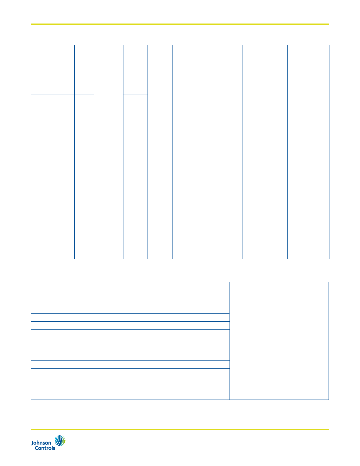
Ordering■Codes
Product■Code
Power■
Supply
Control■
Type
Actuator■
Speed
Nominal■
Force
Actuator■
Stroke■
Field■
Cong.
Factory■
Stroke■
Cong.
Mounting■
Thread■
nut
Cable■
Lenght■
Factory■
mounted
Special■
Cong.
Valve■
Combination
VA-7480-0011
24Vac
Floating
13sec/mm
120N
--- ---
M28x1.5
1.5m
---
VG4000
VG5000
VA-7481-0011 8sec/mm
VA-7480-0013
230Vac
13sec/mm
VA-7481-0013 8sec/mm
VA-7482-0011
24Vac/
Vdc
Proportional 8sec/mm
VA-7482-0311 3m
VA-7480-0001
24Vac
Floating
13sec/mm
M30x1,5
1.5m
V5000
VG6000
VP1000
(DN15 to DN32)
VA-7481-0001 8sec/mm
VA-7480-0003
230Vac
13sec/mm
VA-7481-0003 8sec/mm
VA-7482-1001
24Vac/
Vdc
Proportional 8sec/mm X
3.2mm
VG6000
VP1000
(DN15 and DN20)
VA-7482-1301-RA 3m
Reverse
action
VA-7482-2001 4.3mm
1.5m ---
V5000
VA-7482-3001 6.0mm
VP1000
(DN25 and DN32)
VA-7482-2201-TA
140N 4.3mm
2m
Reverse
action
Tour Anderson
TBV-CM
TBV-CMP
(DN15 and DN20)
VA-7482-2501-TA 5m
Accessories■(order separetely)
Accessories■Code Description Packing
VA-7480-CAB21 Floating 24V – 2 meter length
Plastic Bag
VA-7480-CAB31 Floating 24V – 3 meter length
VA-7480-CAB51 Floating 24V – 5 meter length
VA-7480-CAB71 Floating 24V – 7 meter length
VA-7480-CAB11 Floating 24V – 10 meter length
VA-7480-CAB23 Floating 230V – 2 meter length
VA-7480-CAB33 Floating 230V – 3 meter length
VA-7480-CAB53 Floating 230V – 5 meter length
VA-7480-CAB73 Floating 230V – 7 meter length
VA-7480-CAB13 Floating 230V – 10 meter length
VA-7482-CAB21 Proportional 24V – 2 meter length
VA-7482-CAB31 Proportional 24V – 3 meter length
VA-7482-CAB51 Proportional 24V – 5 meter length
VA-7482-CAB71 Proportional 24V – 7 meter length
PB_VA-748x_12 2012
3
Operation
24Vac Floating Model
When the signal is applied to the black and red wires, the
actuator stem extends. When the signal is removed the
actuator remains in position.
If the signal remains applied to the red wire, the actuator
will time out and shut off the motor after approximately
90 seconds (13 sec/mm models) and approximately
60 seconds (8 sec/mm models).
When the signal is applied to the black and orange wires,
the actuator stem retracts. When the signal is removed
the actuator remains in position.
If the signal remains applied to the orange wire, the
actuator will time out and shut off the motor after
approximately 90 seconds (13 sec/mm models) and
approximately 60 seconds (8 sec/mm models).
End■of■stroke■Conrmation
When the signal is applied in the same direction, the
actuator turns on every 2 hours and drives in the signal
direction for approximately 90 seconds (13 sec/mm models)
and approximately 60 seconds (8 sec/mm models) to
confirm the end of stroke position.
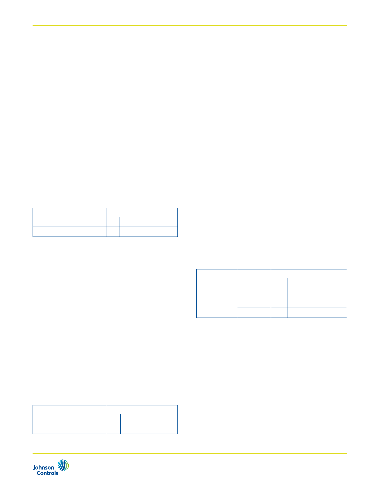
Input Direction
Red wire energised
Actuator stem extends
Orange wire energised
Actuator stem retracts
230Vac Floating Model
When the signal is applied to the blue and brown wires,
the actuator stem extends. When the signal is removed
the actuator remains in position. If the signal remains
applied to the brown wire, the actuator will time out
and shut off the motor after approximately 90 seconds
(13 sec/mm models) and approximately 60 seconds
(8 sec/mm models).
When the signal is applied to the blue and orange wires,
the actuator stem retracts. When the signal is removed
the actuator remains in position. If the signal remains
applied to the orange wire, the actuator will time out
and shut off the motor after approximately 90 seconds
(13 sec/mm models) and approximately 60 seconds
(8 sec/mm models).
End■of■stroke■Conrmation
When the signal is applied continuously in the same
direction, the actuator turns on every 2 hours and drives
in the signal direction for approximately 90 seconds
(13 sec/mm models) and approximately 60 seconds
(8 sec/mm models) to confirm the end of stroke position.
Input Direction
Brown wire energised
Actuator stem extends
Orange wire energised
Actuator stem retracts
24Vac/Vdc Proportional Model
Calibration■Cycle
When the power is applied, the actuator self-calibrates
performing a complete cycle. The actuator moves the
stem down for a complete mechanical valve stroke until
no changes are detected. Once the auto-zero is detected
the actuator moves the stem accordingly with the input
signal.
When the input signal increases (eg. from 0V to 10V) the
actuator stem extends if the actuator is configured as
Direct Action (DA) or retracts if the actuator is configured
as Reverse Action (RA).
When the input signal decreases (eg. from 10V to 0V)
the actuator stem retracts if the actuator is configures as
Direct Action (DA) or extends if the actuator is configured
as Reverse Action (RA).
End■of■stroke■conrmation
For■VA-7482-0011■model■only:■
When the input signal is at 0 or 100%, the actuator
turns on every 2 hours and drives in the signal direction
for approximately 90 seconds (13 sec/mm models) and
approximately 60 seconds (8 sec/mm models) to confirm
the end of stroke position.
For■VA-7482-x001■models:■
When the input signal is at 100% the actuator turns
on every 2 hours and drives in the signal direction for
approximately 60 seconds to confirm the end of stroke
position
Action Input Direction
Direct Acting
0...10Vdc
Actuator stem extends
10...0Vdc
Actuator stem retracts
Reverse Acting
0...10Vdc
Actuator stem retracts
10...0Vdc
Actuator stem extends
PB_VA-748x_12 2012
4
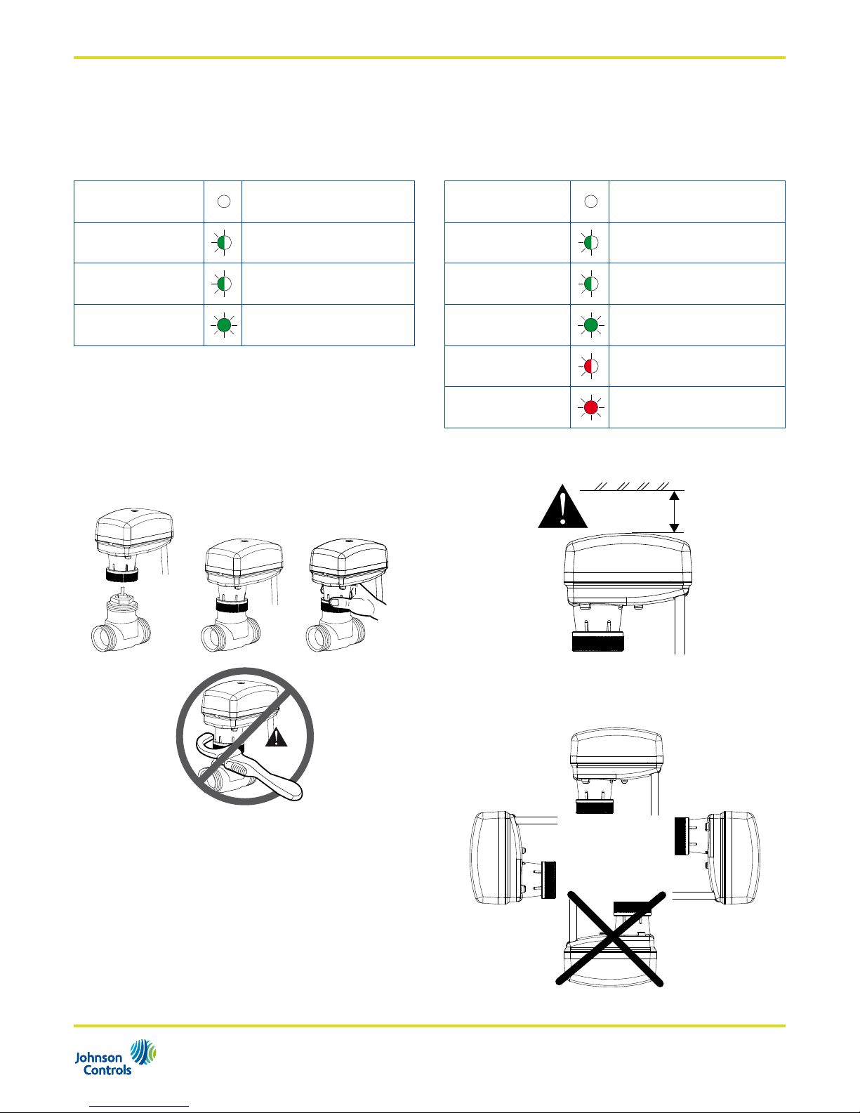
Operating■status■indication
24Vac/ 230Vac Floating Model
The floating models are equipped with a green LED
which provides the information about the operating status
as follow:
OFF No■power■supply
GREEN■BLINKING
Moving■to■position
GREEN■BLINKING
End■stroke■confirmation
GREEN■STEADY■ON
End■Stroke■reached
24Vac/Vdc Proportional Model
The proportional models are equipped with a bi-colour
LED (green-red) which provides the information about the
operating status and diagnostic as follow:
OFF No■power■supply
GREEN■BLINKING
Moving■to■position
GREEN■BLINKING
End■stroke■confirmation
GREEN■STEADY■ON
Position■reached
RED■BLINKING
Cycle
RED■STEADY■ON
4/20mA■or■2/10Vdc■signal■lost
Mounting■Instruction
When mounting the actuator on terminal unit valves,
please follows the instruction below:
OK
NO
Never use the actuator as a mounting lever.
• It is recommended that the valves be mounted upright or at
angles not greater than 90° in an easily accessible location.
• Do not mount the actuator upside down to avoid dripping
water, which could enter the housing and damage the
mechanism or motor.
• Do not cover with insulating material.
• Sufficient clearance must be allowed for actuator removal
(refer to the dimension drawings).
>15 cm
• Mounting position:
 Loading...