

Page 1
VA-7010 Series Electric On/O Actuator
Product Bulletin
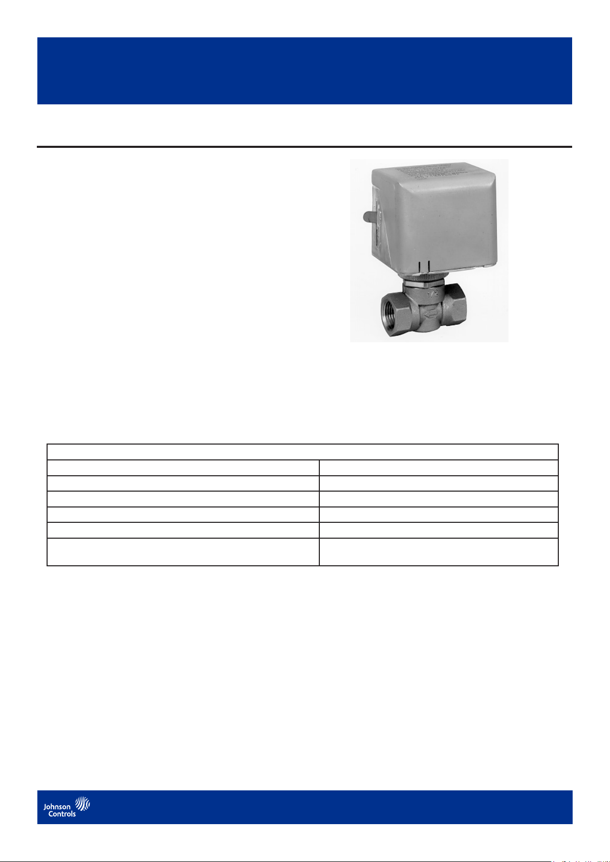
The VA-7010 Series Electric On/Off Actuators provide
two-position (open/closed) control and can easily be
field mounted with a threaded coupling onto VG5000
Series Forged Brass Valves. Refer to the VG5000
Series Forged Brass Valves 1/2 Through 1 in., Two-Way
Normally Closed and Three-Way Product Bulletin (LIT-
977135) for specific information.
A lever at the side of the actuator housing can be used to
open the mounted valve manually for servicing.
LIT-977360
January 2021
Figure 1: VA-7010 Actuator with VG5000 Valve
Features and benets
Low or line voltage model available Application flexibility
AC stall type motor Quiet operation
Manual lever Manual position mode for servicing
Flat profile design with small side clearance Mounting close to flat surfaces saves space
Actuator can be mounted after valve body is installed Simple installation in confined space
Actuator can be rotated after mounting Easy wiring as wiring conduit can be located in any
direction
VA-7010 Series Electric On/O Actuator
1
Page 2
V
Ordering information
A-7010-800
Supply Voltage
1
24 VAC
2
120 VAC
3
230 VAC
Figure 2: Ordering data for the VA-7010
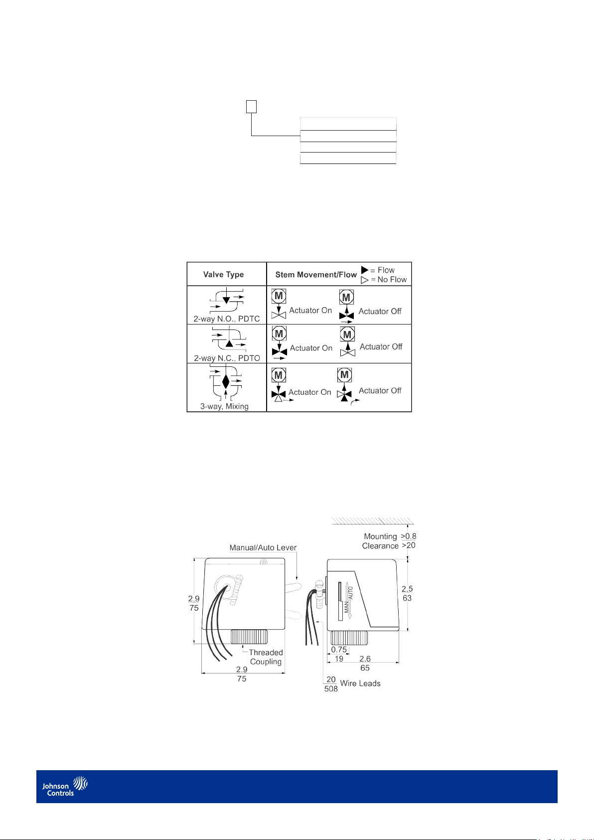
Operation
When power is applied to the actuator, the motor drives the gear assembly, and pushes down on the valve em
again the force of the valve return spring.
When power is removed from the actuator, the actuator retracts and allows the valve return spring to move the valve
em up, in the direction of its normal position. (See Figure 3.)
Figure 3: Flow diagram
Manual override
The VA-7010 actuator features a manual operating lever (shown in Figure 3) for manually opening Normally Closed
(N.C.) valves or the N.C. port of
3-way valves. The lever will not fully close Normally Open (N.O.) valves or the N.O. port of 3-way valves.
Dimensions
Figure 4: Dimensions, in. (mm)
VA-7010 Series Electric On/O Actuator
2
Page 3

Mounting
V
0
P
24
120
230
When mounting the actuator:
• Make sure the actuator is easily accessible for the electrical connections.
• Make sure the actuator is free of thermal insulation material.
• Leave at lea 0.8 in. (20 mm) clearance above the actuator for mounting purposes. (See Figure 3.)
To mount the actuator on a VG5000 valve:
1. Place the threaded coupling over the valve em and the bonnet.
2. Rotate the actuator to the desired position and tighten the coupling securely by hand.
Note: Never use the actuator as a mounting lever.
!
CAUTION: Risk of property damage
Mount the actuator housing only on a valve that is piped 90° of the vertical position so that it is free of dripping water.
Failure to do so could lead to water entering the housing and damaging the mechanism and motor.
Figure 5: Valve/actuator mounting positions
Wiring
!
CAUTION: Risk of electric shock
When servicing the actuator, make sure that the electrical supply to the actuator is turned o. Do not attempt to
connect or disconnect wires when power is applied to the actuator. Failure to do so can cause electric shock and may
result in severe personal injury or death.
!
CAUTION: Risk of property damage
Do not apply power to the syem before checking all wiring connections. Short circuited or improperly connected
wires may result in permanent damage to the equipment. Make all wiring connections in accordance with the National
Electrical Code and all local regulations.
To wire the VA-7010 actuator:
1. Run the actuator wires through 3/8 in. Flexible Metallic Conduit (FMC) or its equivalent as appropriate.
2. Secure the FMC to the connector provided with the actuator by tightening the clamp screw using a 1/4 in. at-
blade screwdriver.
3. Connect the wires as shown in Figure 6 for each respective model voltage.
A-701
Power
Power
Case
Ground
ower
VAC
White
White
N/A
VAC
White
Black
Green
VAC
White
Yellow
Green
Figure 6: VA-7010 wiring diagram
Actuator combinations
The VA-7010 Series Electric Valve Actuators are designed to be used with the VG5000 valve series. Refer to the
VG5000 Series Forged Brass Valves Product Bulletin (LIT-977135) for complete ordering information.
VA-7010 Series Electric On/O Actuator
3
Page 4

VA-7010 Series Electric On/O Actuator
Technical specications
Product VA-7010 Series Electric On/O Actuator
Action On/o
Type of motor Synchronous all
Supply voltage (50/60 Hz) VA7010-8001 24 VAC, Class 2, ±10%
VA7010-8002 120 VAC, ±10%
VA7010-8003 230 VAC, ±10%
Power consumption 7 VA
Minimum force 20.2 lb (90 N)
Nominal roke 0.12 in. (3 mm) maximum 0.2 in. (5mm)
Full roke time on Nominal 10 seconds
Full roke time o Nominal 5 seconds
Enclosure IP40, NEMA 1
Ambient operating condition 35 to 122°F (2 to 50°C), non-condensing
Ambient orage condition -4 to 149°F (-20 to 65°C), non-condensing
Electrical connections 18 AWG, 20 in. (508 mm) long wire leads
Dimensions (H x W x D) 2.9 x 2.9 x 2.6 in. (75 x 75 x 65 mm)
Shipping weight 1.1 lb (0.5 kg)
Agency compliance UL 873 Lied, File E27734, Guide XAPX, Plenum Rated
CSA C22.2 No. 139 Certied, File LR85083, Class 3221 01
CE conformity VA-7010-8001: CE Mark – Johnson Controls declares that this
product is in compliance with the essential requirements and other
relevant provisions of the EMC Directive
The performance specications are nominal and conform to acceptable industry standards. For application at conditions beyond these specications, consult the local
Johnson Controls oce. Johnson Controls shall not be liable for damages resulting from misapplication or misuse of its products.
Product warranty
This product is covered by a limited warranty, details of which can be found at
www.johnsoncontrols.com/buildingswarranty.
Single point of contact
APAC
JOHNSON CONTROLS
C/O CONTROLS PRODUCT MANAGEMENT
NO. 32 CHANGJIJANG RD NEW DISTRICT
WUXI JIANGSU PROVINCE 214028 - CHINA
For more contact information, refer to www.johnsoncontrols.com/locations.
Europe
JOHNSON CONTROLS
WESTENDHOF 3
45143 ESSEN
GERMANY
© Copyright 2021 Johnson Controls. All rights reserved. Any unauthorized use or copying is strictly prohibited.
NA/SA
JOHNSON CONTROLS
507 E MICHIGAN ST
MILWAUKEE WI 53202
USA
Building Technologies & Solutions
Headquarters: Milwaukee, Wisconsin, USA
Branch Offices: Principal Cities Worldwide
Johnson Controls® is registered trademark of Johnson Controls.
All other marks herein are the marks of their respective owners.
www.johnsoncontrols.com
 Loading...