

Page 1
Installation Instructions V-9502-95
Issue Date February 10, 2003
MP8000 Series Actuated Valves with
V-9502-95 Pneumatic Valve Actuator Positioner
Application
The V-9502-95 Pneumatic Valve Actuator Positioner is
a precision relay device designed to operate a
Johnson Controls MP8000 Series Valve Actuator in
applications requiring stable, accurate control. The
V-9502-95 provides maximum positioning power to
resist external forces which might otherwise overcome
the positioning power of the valve actuator. Adjustable
operating span and starting point also make the
V-9502-95 an ideal choice for valve sequencing
applications.
The V-9502-95 Positioner is mounted to the
MP8000 Series Actuator using an MP8000-6002
Positioner Mounting Kit (ordered separately). This
mounting kit contains six color-coded springs and all of
the necessary mounting hardware (as outlined in
Table 1).
Installation
Table 1: Contents of MP8000-6002 Positioner
Mounting Kit
Quantity Description
2
1
1
1
1
1
1
1
1
1
1
2
1
Yoke Bushings
Connector Bracket
Connector Arm
Yellow Spring (5/16 in. Stroke)
Blue Spring (1/2 in. Stroke)
White Spring (3/4 in. Stroke)
Gray Spring (1 in. Stroke)
Green Spring (1-1/4 in. Stroke)
Red Spring (1-1/2 in. Stroke)
Phillips-Head, Taptite Screw,
No. 8-32 x 1-1/4 in. (32 mm) Long
Phillips-Head, Taptite Screw,
No. 8-32 x 5/8 in. (16 mm) Long
Phillips-Head, Taptite Screws,
No. 6-32 x 1/4 in. (6 mm) Long
12 in. (305 mm) Length of
Black Plastic Tubing
© 2003 Johnson Controls, Inc.
Part No. 14-1161-68, Rev. A www.johnsoncontrols.com
1
Page 2
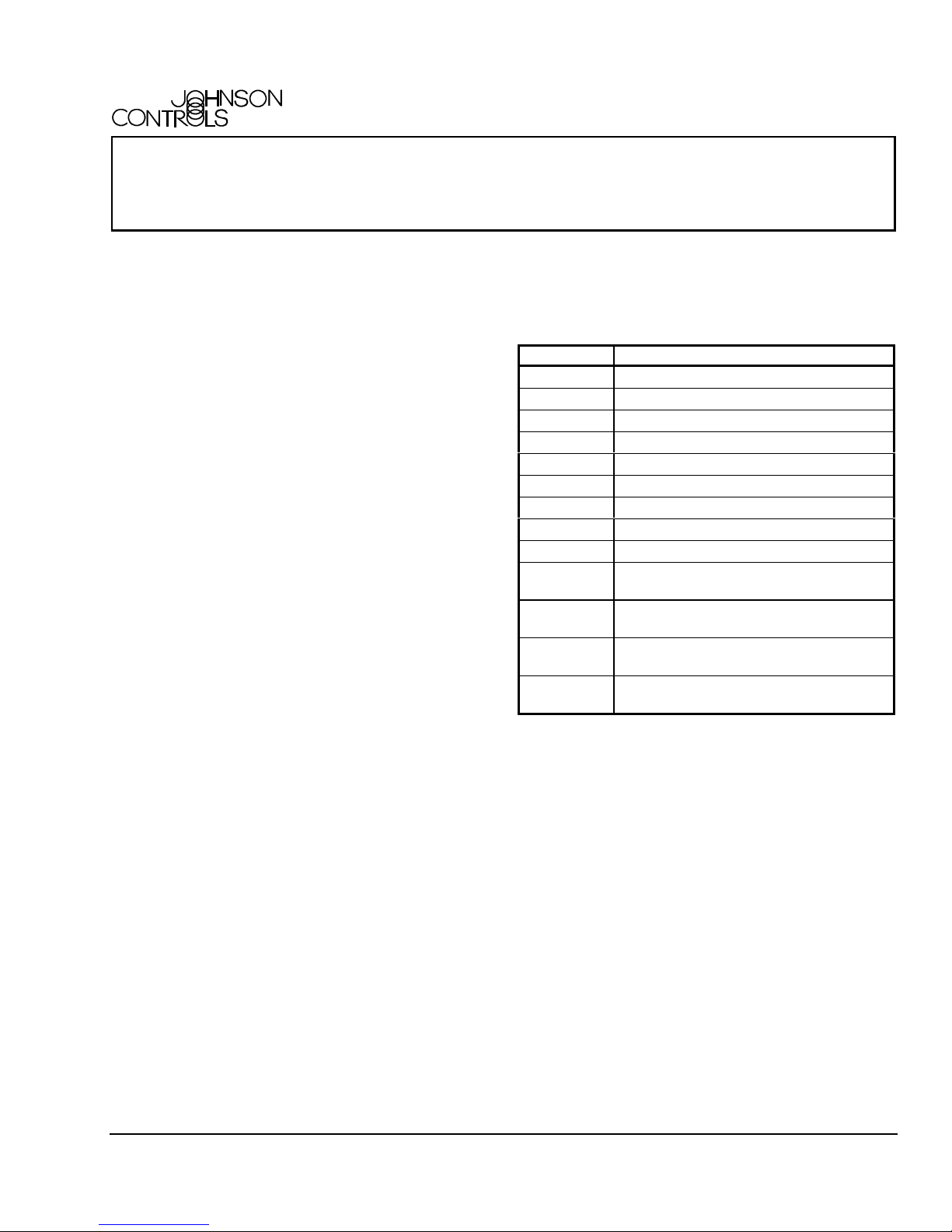
Mounting
Positioner
Operating Span
Lever Arm
Positioner
Cover
Cover
Screw
Color-Coded
Spring
No. 8-32 x 5/8 in. (16 mm)
Phillips-Head Taptite Screw
No. 8-32 x 1-1/4 in. (32 mm)
Phillips-Head Taptite Screw
Yoke Bushings
(Two Locat ions)
Connector
Arm
Actuator
Stem Connector
Upper
Jam Nut
No. 6-32 x 1/4 in. (6 mm)
Phillips-Head Taptite Screws
(Two Locat ions)
Connector
Bracket
Yoke Bushings
(Two Locat ions)
Actuator
Yoke
Figure 1: Mounting the V-9502-95 Pneumatic Valve Actuator Positioner
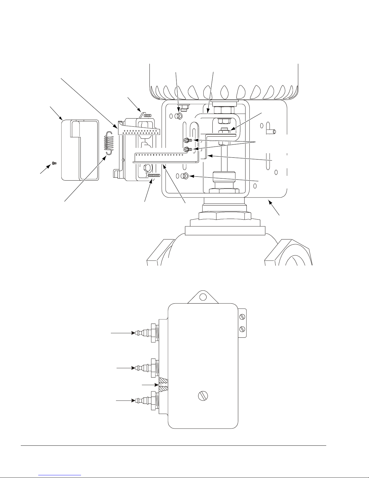
Pilot
Output
Output H y podermic
Needle Test Point
Supply
P
O
S
Figure 2: V-9502-95 Port Identification
2 MP8000 Series Actuated Valves with V-9502-95 Pneumatic Valve Actuator Positioner Installation Instructions
Page 3

Refer to Figures 1 and 2, and mount the V-9502-95
Pneumatic Valve Actuator Positioner to an
MP8000 Series Valve Actuator using the
MP8000-6002 Positioner Mounting Kit as follows:
1. Disconnect the supply air to the MP8000 Series
Actuator.
2. Loosen the cover screw on the V-9502-95
Positioner and remove the cover.
3. Locate the side of the actuator yoke that has two
circular holes.
4. Insert the two yoke bushings into the circular
holes from the inside of the actuator yoke.
5. Secure the V-9502-95 Positioner to the side of
the actuator yoke using the two No. 8-32 taptite
screws and two yoke bushings.
Note: Be certain to orient the V-9502-95 Positioner
so that the 5/8 in. (16 mm) taptite screw is closest to
the MP8000 Series Actuator, and the 1-1/4 in. (32 mm)
taptite screw is closest to the valve body.
6. Secure the connector arm to the connector
bracket using the two No. 6-32 x 1/4 in. (6 mm)
taptite screws.
12. Tighten the two No. 6-32 taptite screws to secure
the connector arm to the connector bracket.
13. Connect the pneumatic input signal to the Pilot P
port of the V-9502-95 Positioner.
14. Use the 12 in. (305 mm) length of black plastic
tubing included in the MP8000-6002 Kit to
connect the Output O port of the V-9502-95
Positioner to the input of the MP8000 Series
Actuator.
15. Connect a nominal 20 psig (138 kPa) supply
pressure to the Supply S port of the V-9502-95
Positioner.
16. Commission the V-9502-95 Positioner as outlined
in the Setup and Adjustments section. If the
V-9502-95 Positioner will be commissioned at a
later time, re-install the positioner cover and
tighten the cover screw.
Setup and Adjustments
Starting Point
Adjusting Screw
7. Install the connector arm and connector bracket
assembly onto the valve stem, between the
actuator stem connector and the upper jam nut.
Note: The connector arm should be positioned
below and parallel to the positioner operating span
lever arm.
8. Select the appropriate color-coded spring for the
required valve stroke. Refer to Table 1 for the
color-coded stroke designations.
9. Install one end of the spring into the positioner
operating span lever arm. Initially, install the
spring into the seventh hole on the positioner
operating span lever arm. This hole represents an
operating span of approximately 4 psi (28 kPa).
Note: The hole closest to the V-9502-95 Positioner
represents the first hole in the series.
10. Install the other end of the color-coded spring into
the appropriate hole in the connector arm that
allows the spring to be positioned parallel to the
V-9502-95 Positioner body.
11. Loosen the two No. 6-32 taptite screws that
secure the connector arm to the connector
bracket, and reposition the connector arm until
the color-coded spring is just taut but not
stretched.
3 psi (21 kPa )
Span
Operating
Span
Selection
13 psi (90 kPa)
Span
Positioner
Operating
Span
Lever Arm
Figure 3: Setting Up the
V-9502-95 Positioner for Operation
The following procedure is a typical example of how a
V-9502-95 Pneumatic Valve Actuator Positioner is
used to adjust the operating spring range and change
the operating span of an MP8000 Series actuated
valve assembly.
Assume that the MP8000 Series Actuator has an
operating spring range of 4 to 8 psig (28 to 55 kPa)
resulting in an operating span of 4 psi (28 kPa), and
that it is desirable to obtain an operating spring range
of 3 to 8 psig (21 to 55 kPa) resulting in an operating
span of 5 psi (34 kPa).
MP8000 Series Actuated Valves with V-9502-95 Pneumatic Valve Actuator Positioner Installation Instructions 3
Page 4

To make the change, refer to Figure 3 and proceed as
follows:
1. Connect a nominal 20 psig (138 kPa) supply
pressure to the Supply S port of the V-9502-95
Positioner.
2. Install one end of the color-coded spring into the
hole in the positioner operating span lever arm
that corresponds to a 5 psi (34 kPa) operating
span.
Note: The ninth hole on the positioner operating
span lever arm represents an operating span of
approximately 5 psi (34 kPa). The hole closest to the
V-9502-95 Positioner represents the first hole in the
series.
3. Reposition the other end of the color-coded
spring so that the spring is parallel to the
V-9502-95 Positioner body.
4. Connect a 3 psig (21 kPa) pneumatic input signal
to the Pilot P port of the V-9502-95 Positioner.
5. If the V-9502-95 Positioner cover is not already
removed, loosen the cover screw and remove the
cover.
6. Turn the starting point adjusting screw clockwise
until the actuator just begins to stroke. An output
pressure reading can be taken either by using a
pressure gauge in the V-9502-95 Positioner
output line, or at the hypodermic needle test point
on the positioner body.
7. Increase the pneumatic input signal to 8 psig
(55 kPa). At this point, the valve should be fully
stroked.
Note: In some instances, turning the starting point
adjusting screw will affect the operating span of the
actuator and valve assembly. If the operating span is
affected, install the color-coded spring into a different
hole on the positioner operating span lever arm and
repeat Steps 3 through 7.
If the spring is re-installed into a top hole on the
positioner operating span lever arm, the connector arm
may need to be repositioned to ensure that the
color-coded spring is not stretched beyond just taut.
Refer to Step 11 in the Mounting section for more
details.
8. Re-install the V-9502-95 Positioner cover and
tighten the cover screw. The V-9502-95
Positioner is now ready to position the
MP8000 Series Actuator over an operating spring
range of 3 to 8 psig (21 to 55 kPa).
Controls Group
507 E. Michigan Street
P.O. Box 423 Published in U.S.A.
Milwaukee, WI 53201 www.johnsoncontrols.com
4 MP8000 Series Actuated Valves with V-9502-95 Pneumatic Valve Actuator Positioner Installation Instructions
 Loading...