

Page 1
V-9000 Series Rotary Motion Rack and Pinion
Pneumatic Actuators for Butterfly Valves
Butterfly Valves and Actuators
Code No. LIT-1924085
V-9000 Series Rotary Motion Rack and Pinion Pneumatic Actuators for Butterfly
Valves
Description
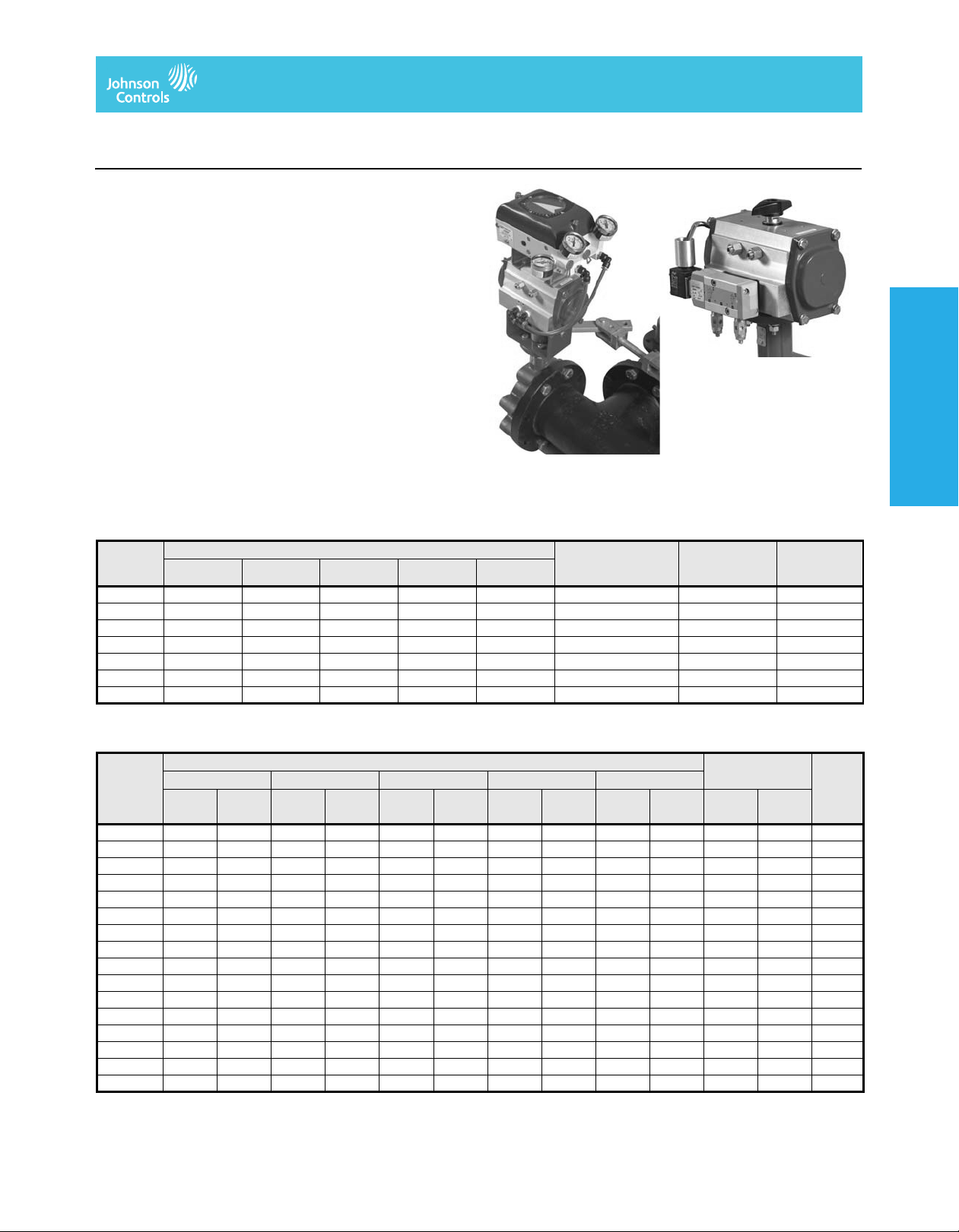
The V-9000 Series Rack and Pinion Pneumatic Actuators are
designed for direct mounting on Johnson Controls® VF Series
Butterfly Valves. The actuators are available in eight sizes with torque
output capacities capable of automating VF Series Butterfly Valves up
to 20 in. (508 mm) in size.
Refer to the V-9000 Series Rotary Motion Rack and Pinion Pneumatic
Actuators for Butterfly Valves (LIT-977260) for important product
application information.
Features
• compact modular design
• low-friction piston guides and rings
• built-in shaft position indicator and travel stops
• full range of modular add-on control accessories
Repair Information
If the V-9000 Series Pneumatic Actuator fails to operate within its
specifications, replace the unit. For a replacement actuator, contact
the nearest Johnson Controls representative.
Selection Charts
V-909x Series Actuator Torque Data (lb·in) and Ordering Data (Double Acting)
Code
Number
V-9092-1 145 221 297 373 449 -020 9.35 3.4
V-9093-1 351 536 721 906 1,091 -030 20.5 6.3
V-9094-1 493 753 1,013 1,272 1,532 -040 28.9 8.5
V-9094-2 1,058 1,615 2,171 2,728 3,285 -042 62.0 16.9
V-9096-1 2,797 4,270 5,742 7,214 8,687 -060 140.6 38.8
V-9097-1 5,783 8,826 11,870 14,914 17,957 -070 309.5 77.8
V-9098-1 14,211 21,691 29,171 36,650 44,130 -080 734.1 167.0
1. Refer to the ordering data templates in the VF Series Standard-Pressure, Standard-Temperature Butterfly Valves Product Bulletin (LIT-977205P) and the
VF Series High-Pressure, High-Temperature Butterfly Valves Product Bulletin (LIT-977208) for full code numbers.
V-919x Series Actuator Torque Data (lb·in) and Ordering Data (Spring Return) (Part 1 of 2)
Code
Number
V-9193-12 210 167 395 352 580 537 765 722 950 907 184 141 6.0
V-9193-13 156 76 341 261 526 446 711 631 896 816 275 195 6.3
V-9193-14 281 176 466 361 651 546 836 731 360 255 6.6
V-9193-16 369 185 554 370 739 555 536 352 7.1
V-9194-12 310 232 570 492 830 752 1,089 1,011 1,349 1,271 261 183 8.0
V-9194-13 218 101 478 361 738 621 997 880 1,257 1,140 392 275 8.4
V-9194-14 386 231 646 491 905 750 1,165 1,010 522 367 8.8
V-9194-15 294 94 554 354 813 613 1,073 873 659 459 9.1
V-9194-16 462 229 721 488 981 748 784 551 9.5
V-9194-22 692 469 1,249 1,026 1,805 1,582 2,362 2,139 2,919 2,696 589 366 18.1
V-9194-23 509 174 1,066 731 1,622 1,287 2,179 1,844 2,736 2,401 884 549 18.8
V-9194-24 883 437 1,439 993 1,996 1,550 2,553 2,107 1,178 732 19.5
V-9194-25 700 142 1,256 698 1,813 1,255 2,370 1,812 1,473 915 20.3
V-9194-26 1,073 404 1,630 961 2,187 1,518 1,767 1,098 21.0
V-9195-13 1,357 733 2,099 1,475 2,841 2,217 3,583 2,959 1,419 795 22.1
V-9195-15 1,568 529 2,310 1,271 3,052 2,013 2,365 1,326 24.2
Supply Pressure, psig (kPa) VF Series Code
40 (280) 60 (420) 80 (560) 100 (700) 120 (840)
Air Stroke Supply Pressure, psig (kPa) Spring Stroke Weight,
40 (280) 60 (420) 80 (560) 100 (700) 120 (840)
NC1
Start
NO1
End
NC
Start
NO
End
NC
Start
NO
End
NC
Start
Number
NO
End
1
NC
Start
Actuator Air
Volume,
cubic in.
NO
End
NO
Start
Shipping
Weight,
lb
lb
NC
End
Actuators
Actuators
Actuators
Actuators
Pneumatic Damper
Pneumatic Damper
Buttery Valves and
Buttery Valves and
The performance specifications are nomina l and con form to accep table ind ustry stand ards. For applicati ons at con ditions be yond these specification s, consult th
Johnson Controls, Inc. shall not be liable for damages resulting from misapplication or misuse of its products. © 2014 Johnson Controls, Inc.
V–297
Page 2
V-9000 Series Rotary Motion Rack and Pinion Pneumatic Actuators for Butterfly Valves
(Continued)
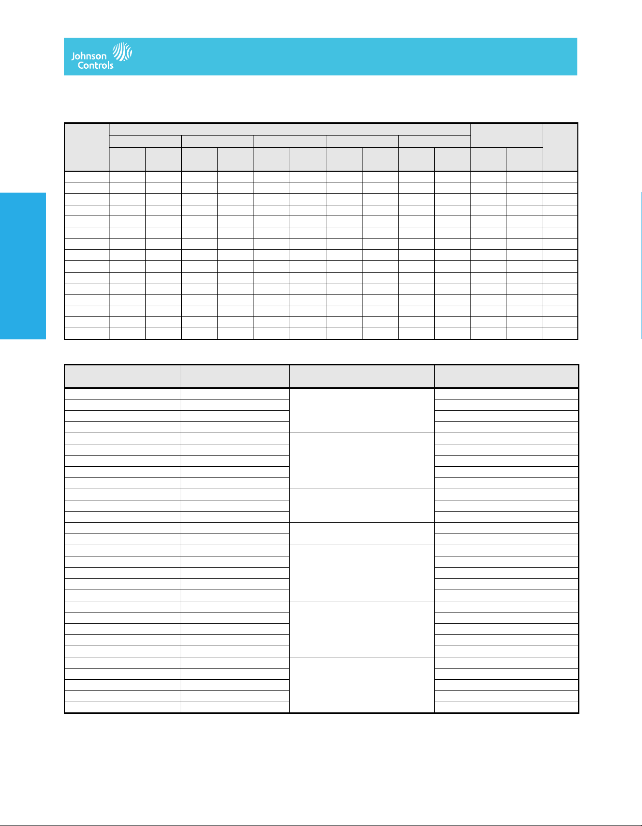
V-919x Series Actuator Torque Data (lb·in) and Ordering Data (Spring Return) (Part 2 of 2)
Code
Number
V-9196-12 1,819 1,118 3,292 2,591 4,764 4,063 6,236 5,535 7,709 7,008 1,679 978 39.7
V-9196-13 1,399 349 2,872 1,822 4,344 3,294 5,816 4,766 7,289 6,239 2,448 1,398 42.1
V-9196-14 2,452 1,123 3,924 2,595 5,396 4,067 6,869 5,540 3,147 1,818 44.5
V-9196-15 2,030 353 3,502 1,825 4,974 3,297 6,447 4,770 3,917 2,240 46.8
V-9196-16 3,154 1,196 4,626 2,668 6,099 4,141 4,546 2,588 49.2
V-9197-12 3,833 2,508 6,876 5,551 9,920 8,595 12,964 11,639 16,007 14,682 3,275 1,950 75.1
V-9197-13 2,859 868 5,902 3,911 8,946 6,955 11,990 9,999 15,033 13,042 4,915 2,924 80.2
V-9197-14 4,930 2,275 7,974 5,319 11,018 8,363 14,061 11,406 6,551 3,896 85.2
V-9197-15 3,949 638 6,993 3,682 10,037 6,726 13,080 9,769 8,188 4,877 90.3
V-9197-16 6,022 2,031 9,066 5,075 12,109 8,118 9,839 5,848 95.3
Actuators
Actuators
V-9198-12 9,487 6,747 16,967 14,227 24,447 21,707 31,926 29,186 39,406 36,666 7,464 4,724 160.2
V-9198-13 7,125 3,015 14,605 10,495 22,085 17,975 29,564 25,454 37,044 32,934 11,196 7,086 168.3
Pneumatic Damper
Buttery Valves and
V-9198-14 12,243 6,762 19,723 14,242 27,202 21,721 34,682 29,201 14,929 9,448 176.4
V-9198-15 9,880 3,030 17,360 10,510 24,839 17,989 32,319 25,469 18,661 11,811 184.5
V-9198-16 14,998 6,778 22,477 14,257 29,957 21,737 22,393 14,173 192.6
1. N.C. is the abbreviation for Normally Closed; N.O. is the abbreviation for Normally Open.
V-919x Series Ordering Data
Code Number
V-9193-12 -320 32.6 4
V-9193-13 -330 6
V-9193-14 -340 8
V-9193-16 -360 12
V-9194-12 -420 45.9 4
V-9194-13 -430 6
V-9194-14 -440 8
V-9194-15 -450 10
V-9194-16 -460 12
V-9194-22 -422 95.5 4
V-9194-23 -432 6
V-9194-24 -442 8
V-9195-13 -530 130.8 6
V-9195-15 -550 10
V-9196-12 -620 259.6 4
V-9196-13 -630 6
V-9196-14 -640 8
V-9196-15 -650 10
V-9196-16 -660 12
V-9197-12 -720 450 4
V-9197-13 -730 6
V-9197-14 -740 8
V-9197-15 -750 10
V-9197-16 -760 12
V-9198-12 -820 900 4
V-9198-13 -830 6
V-9198-14 -840 8
V-9198-15 -850 10
V-9198-16 -860 12
1. Refer to the ordering data templates in the VF Series Standard-Pressure, Standard-Temperature Butterfly Valves Product Bulletin (LIT-977205P) and the
VF Series High-Pressure, High-Temperature Butterfly Valves Product Bulletin (LIT-977208) for full code numbers.
2. The numbers listed are the total number of springs in the actuator; the last digit of the code number suffix indicates the number of springs per piston. There are
two pistons per actuator.
Air Stroke Supply Pressure, psig (kPa) Spring Stroke Weight,
40 (280) 60 (420) 80 (560) 100 (700) 120 (840)
NC1
Start
NO1
End
NC
Start
NO
End
NC
Start
VF Series Code Number
Butterfly Valves and Actuators
NO
End
1
Total Actuator Air Volume Required
for 90° Rotation, cubic in.
NC
Start
NO
End
NC
Start
NO
End
Total Number of Springs in
Actuator
NO
Start
2
NC
End
lb
The performance specifications are no minal and co nform t o acceptab le ind ustry standar ds. For appl ications at condition s beyond these specifica tions, consult th
Johnson Controls, Inc. shall not be liable for damages resulting from misapplication or misuse of its products. © 2014 Johnson Controls, Inc.
V–298
Page 3

Butterfly Valves and Actuators
V-9000 Series Rotary Motion Rack and Pinion Pneumatic Actuators for Butterfly Valves
(Continued)
Accessories
Solenoid Valves Including Mounting Hardware
Code Number and Features Description
V-9000-146
V-9000-147
Features Voltage Requirements 120 VAC
1. For actuators manufactured after April 1, 1992
1
1
Power Consumption AC: 5.6 VA; DC: 7.2 W
Maximum Pressure 140 psig (980 kPa)
Ambient Temperature Limits 0 to 180°F (-18 to 82°C)
Air Connections 1/4 in. NPT (Internal )
Electrical Connections 18 AWG Leads, 24 in. (61 cm) Long
Enclosure Materials Die-Cast Aluminum Body with NEMA 4 Coil Housing
120 VAC Solenoid Air Valve, Four-Way, for New Style
V-9092 to V-9094-1 and V-9193 to V-9194-1 Series Actuators
120 VAC Solenoid Air Valve, Four-Way, for New Style
V-9094-2 to V-9098 and V-9194-2 to V-9198 Series Actuators
Speed Controls
Code Number Description
V-9000-311 Brass Speed Controls (Two) for New Style
V-9192 to V-9194-2 Series Actuators
V-9000-312 Brass Speed Controls (Two) for New Style
V-9194-2 to V-9198 Series Actuators
1. For actuators manufactured after April 1, 1992
1
1
Plastic Position Indicators
Actuator Series
V-9x92 V-9092-611
V-9x93 V-9093-611
V-9x94-1x V-9094-6111
V-9x94-2x V-9094-6112
V-9x95 V-9095-611
V-9x96 V-9096-611
V-9x97 V-9097-611
V-9x98 V-9098-611
1. For actuators manufactured after April 1, 1992
Code Number
1
Positioners
Code Number and Specifications Description
Models V-9000-500 Pneumatic Positioner for All Old and New Style
Mounting Kits
Air
Specifications
Air
Connections
Materials Body Aluminum, Anodized
1. For actuators manufactured before April 1, 1992
2. For actuators manufactured after April 1, 1992
The performance specifications are no minal and co nform t o acceptab le ind ustry standar ds. For appl ications at condition s beyond these specifica tions, consult th
Johnson Controls, Inc. shall not be liable for damages resulting from misapplication or misuse of its products. © 2014 Johnson Controls, Inc.
V-9000-502
V-9000-511
V-9000-512
V-9000-513
Supply Pressure 40 to 140 psig (280 to 980 kPa)
Output Flow Capacity 2, 000 scim (546 mL/s) at 60 psig (420 kPa)
Air Consumption 1,200 scim (328 mL/s) at 60 psig (420 kPa)
Control Action Direct or Reverse; Field Selectable
Operating Range Factory Set at 3 to 15 psig (21 to 105 kPa) for 90° Rotation;
Starting Point Factory Set at Approximately 3 psig (21 kPa)
Ambient Temperature Limits -5 to 160°F (-21 to 71°C)
Supply 1/4 in. NPT (Internal)
Control Input 1/8 in. NPT (Internal)
Outputs 1/8 in. NPT (Internal)
Diaphragm Buna-N Rubber
Spool Stainless Steel
Cover Polycarbonate
1
2
2
2
V-9000 Series Actuators (Includes Three Gauges)
Positioner Mounting Kit for Old-Style V-9x94 and V-9x95 Series Actuators
Positioner Mounting Kit for New Style V-9x92 to V-9x94-1 Series Actuators
Positioner Mounting Kit for New Style V-9x94-2 and V-9x95 Series Actuators
Positioner Mounting Kit for New Style V-9x96 to V-9x98 Series Actuators
Air Supply Must be Clean (Filtered), Dry, and Oil Free.
Field Selectable at 3 to 15 psig for 65° Rotation or 3 to 9 psig
(21 to 63 kPa) or 9 to 15 psig (63 to 105 kPa) for 65° Rotation
Actuators
Actuators
Actuators
Actuators
Pneumatic Damper
Pneumatic Damper
Buttery Valves and
Buttery Valves and
V–299
Page 4

V-9000 Series Rotary Motion Rack and Pinion Pneumatic Actuators for Butterfly Valves
(Continued)
Travel Switches
Code Number and Specifications Description
Travel Limit
Switch Models
Mounting Kits
Features Switches Two Single-Pole, Double-Throw (SPDT)
1. For actuators manufactured before April 1, 1992
2. For actuators manufactured after April 1, 1992
3. Mounting kits are not required for smaller size actuators (V-9x92 through V-9x95).
Pneumatic Rack and Pinion Actuator Adapter Sleeves
Actuators
Actuators
Valve Size, in. V-9x92-xx V-9x93-xx V-9x94-1x V-9x94-2x V-9x95-xx V-9x96-xx V-9x97-xx V-9x98-xx
Pneumatic Damper
Buttery Valves and
2 Not Required V-9094-300 V-9094-300 V-9095-300 V-9095-300
2-1/2 Not Required V-9094-300 V-9094-300 V-9095-300 V-9095-300
3 Not Required V-9094-300 V-9094-300 V-9095-300 V-9095-300
4 V-9094-400 V-9094-400 V-9095-400 V-9095-400
5 Not Required Not Required V-9095-600 V-9095-600 V-9096-600
6 Not Required Not Required V-9095-600 V-9095-600 V-9096-600
8 V-9095-800 V-9095-800 V-9096-800 V-9097-800
10 Not Required Not Required Not Required V-9097-120
12 Not Required Not Required Not Required V-9097-120
14 V-9097-160 V-9098-100
16 V-9097-160 V-9098-100
18 Not Required V-9098-200
20 Not Required V-9098-200
1. Adapter sleeves are required to field mount rack and pinion actuators to VFM valves.
Butterfly Valves and Actuators
V-9000-400
V-9000-401
V-9000-402
V-9000-403
V-9000-404
Electrical Rating 5 A at 120/250 VAC; 5 A at 24 VDC
Body Materials Die-Cast Aluminum, NEMA 4, 4x Housing
1
1
1
1
2
For All V-9000 Series Actuators
For V-9x92 and V-9x93 Series Actuators
For V-9x94 and V-9x95 Series Actuators
For V-9x96 and V-9x97 Series Actuators
For V-9x96, V-9x97, and V-9x98 Series Actuators
1
3
Technical Specifications
V-9000 Series Rotary Motion Rack and Pinion Pneumatic Actuators for Butterfly Valves
Models V-909x Series Rack and Pinion Double Acting Actuators; See V-909x Series Actuator Torque Data
V-919x Series Rack and Pinion Spring-Return Actuators; See V-919x Series Actuator Torque Data
Output Torque V-909x Series See V-909x Series Actuator Torque Data (lb·in) and Ordering Data (Double Acting)
V-919x Series See V-919x Series Actuator Torque Data (lb·in) and Ordering Data (Spring Return)
Supply Pressure Nominal 60 to 80 psig (420 to 560 kPa);
Ambient Temperature Limits -13 to 200°F (-25 to 93°C)
Materials Body Extruded Aluminum, Anodized
End Caps Die Cast Aluminum, Polyester Coated
Pistons Die Cast Aluminum
Output Shaft Carbon Steel, Zinc Plated
Piston Guides Acetal
Spring Cartridges Coated Spring Steel, Zinc Plated Hardware
O-Ring Seals Buna-N Rubber
(lb·in) and Ordering Data (Double Acting) Table for Full Code Numbers.
(lb·in) and Ordering Data (Spring Return) Table for Full Code Numbers.
Minimum 40 psi (280 kPa), Maximum 140 psi (980 kPa).
Air Supply Must be Clean (Filtered), Dry, and Oil Free.
.
.
The performance specifications are no minal and co nform t o acceptab le ind ustry standar ds. For appl ications at condition s beyond these specifica tions, consult th
Johnson Controls, Inc. shall not be liable for damages resulting from misapplication or misuse of its products. © 2014 Johnson Controls, Inc.
V–300
 Loading...