

Page 1
V43 Pressure Actuated Valve
Valves and Valve Accessories
Code No. LIT-1927325
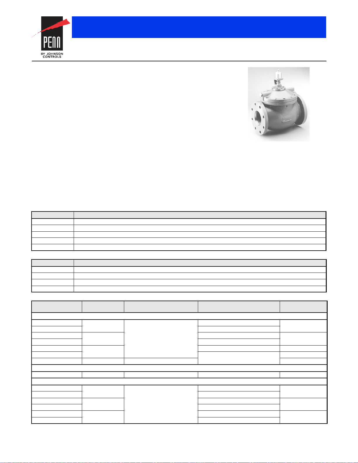
V43/V243 Series Pressure-Actuated Water-Regulating Valves
Description
The V43/V243 Pressure Actuated Water
Regulating Valves are designed to regulate
water flow through the condenser of large
refrigerated cooling systems. These
pilot-operated valves open on an increase in
refrigerant head pressure and provide
modulating operation.
The V43/V243 water regulating valves are
available for commercial and maritime
applications.
V43 valves are available for non-corrosive
low- and medium-pressure refrigerants such
as R-134A, R-404A, R-502, and R-507.
Specially designed V43 valves are also
available for ammonia service (R-717).
V243 valves are available for non-corrosive
high-pressure refrigerants such as R410A.
Commercial V43/V243 valves are
constructed with a cast iron body, brass
internal parts, and bronze seat material.
Valve Construction and Pressure Type
Designator Construction and Pressure Type
A Commercial Service with Iron Body, Open on Pressure Increase, V43
B Maritime Service with Brass Body, Open on Pressure Increase, V43
C Navy Service with Brass Body, Open on Pressure Increase, V43
G Commercial Service with Iron Body, Open on Pressure Increase, V243
H Maritime Service with Brass Body, Open on Pressure Increase, V243
Flange Size
Designator Flange Size
S 2 in.
T 2-1/2 in.
V 3 in.
W 4 in.
V43 Series Pressure Actuated Water Valves (except NAVSEA valves)
Product Code
Number
V43AS-1C 2 Four Hole ASME Flanged 70 to 150 (483 to 1,034) 59 (26.76)
V43AS-2C 160 to 260 (1,103 to 1,793)
V43AT-1C 2-1/2 70 to 150 (483 to 1,034) 65 (29.48)
V43AT-2C 140 to 260 (1,103 to 1,793)
V43AV-1C 3 70 to 150 (483 to 1,034) 90 (40.82)
V43AV-2C 160 to 260 (1,103 to 1,793) 90 (40.82)
V43AW-2C 4 Eight Hole ASME Flanged 142 (64.41)
V43AV-5C 3 160 to 260 (1,103 to 1,793) 90 (40.82)
V43BS-6C 2 Four Hole ASME Flanged 70 to 150 (483 to 1,034) 59 (26.76)
V43BS-7C 160 to 260 (1,103 to 1,793)
V43BT-6C 2-1/2 70 to 150 (483 to 1,034) 65 (29.48)
V43BT-7C 140 to 260 (1,103 to 1,793)
V43BV-10C 3 70 to 150 (483 to 1,034) 90 (40.82)
V43BV-7C 140 to 260 (1,103 to 1,793)
Pipe Size (in.) Inlet and Outlet Opening Point Adjustment Range
To resist the corrosive action of sea water, the
V43/V243 maritime and navy models are
constructed with a red brass body, bronze
and monel interior parts, and monel seat
material.
Refer to the V43/V243 Pressure Actuated
Water Regulating Valves Product/Technical
Bulletin (LIT-125683) for important product
information.
Features
• built-in pilot valve allows more precise
throttling
• easy adjustment allows service and
adjustment without breaking line
connections
• drain plug allows water to be drained
during shutdown to reduce the possibility
of freeze-up
• mesh monel screen protects pilot valve
from items such as dirt and scale and is
easily removed for cleaning and servicing
without breaking any line connections
psig (kPa)
Commercial Type – Non-Corrosive Refrigerants (R)
Commercial Type - Ammonia (R)
Maritime Type – Non-Corrosive Refrigerants (R)
Selection Charts
When ordering V43 valves, specify the
complete product code number including an
optional companion flange and gasket kit. A
companion flange and gasket kit is required to
mount the water lines to commercial type
V43/V243 water-regulating valves.
Shipping Wt. lb (kg)
The performance specifications are nomina l and con form to accep table ind ustry stand ards. For applicati ons at con ditions be yond these specification s, consult th
Johnson Controls, Inc. shall not be liable for damages resulting from misapplication or misuse of its products. © 2015 Johnson Controls, Inc.
R-145
Page 2
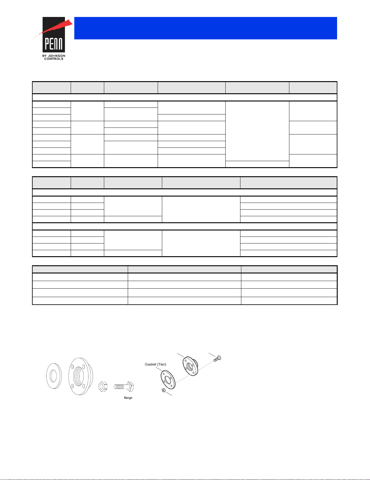
KIT14A
FLG15A
Cast Iron Flange (Two)
Hex Nut (Eight)
Machine Bolt (Eight)
FIG:FLG15A
Ring
Gasket (Two)
Cast Iron
Flange (Two)
Hex
Nut (Eight)
Machine
Bolt (Eight)
Valves and Valve Accessories
V43/V243 Series Pressure-Actuated Water-Regulating Valves (Continued)
Selection Charts (Continued)
V43 Series Pressure Actuated Water valves, Navy NAVSEA Certified
Product Code
Number
V43BS-3C 2 Four Hole ASME Flange 1/4 in. External Flared Connector 70 to 150 (483 to 1,034) 59 (26.76)
V43CS-1C Six Hole Navy Flange
V43CS-2C Internal Sweat Connector
V43BT-3C 2-1/2 Four Hole ASME Flange 1/4 in. External Flared Connector 65 (29.48)
V43CT-2C Six Hole Navy Flange
V43BV-4C 3 Four Hole ASME Flange Internal Sweat Connector 90 (40.82)
V43CV-1C Eight Hole Navy Flange 1/4 in. External Flared Connector
V43CV-2C Internal Sweat Connector
V43BW-7C 4 Eight Hole ASME Flange 1/4 in. External Flared Connector 142 (64.41)
V43BW-2C 140 to 260 (1,103 to 1,793)
V243 Series Pressurized Actuated Water Valves
Product Code
Number
V243GS-1C 2 Four Hole ASME Flange 200 to 400 (1,379 to 2,758) 59 (26.76)
V243GT-1C 2-1/2 65 (29.48)
V243GV-1C 3 90 (40.82)
V243GW-1C 4 Eight Hole ASME Flange 142 (64.41)
V243HS-1C 2 Four Hole ASME Flange 200 to 400 (1,379 to 2,758) 59 (26.76)
V243HT-1C 2-1/2 65 (29.48)
V243HV-1C 3 90 (40.82)
V243HW-1C 4 Eight Hole ASME Flange 142 (64.41)
Accessories
Kit Code Number Water Valve Size (in.) Shipping Weight, lb (kg)
KIT14A-613
KIT14A-614
FLG15A-600
FLG15A-601
1. Commercial valves only.
2. These are the parts included in the flange and gasket kit for the 2-inch and 2-1/2 inch valves.
3. These are the parts included in the flange and gasket kit for the 3-inch and 4-inch valves.
1, 2
1, 2
1, 3
1, 3
Pipe Size
(in.)
Pipe Size
(in.)
Inlet and Outlet Pressure Connector Opening Point Adjustment
Range – psig (kPa)
Navy NAVSEA Certified – Non-Corrosive Refrigerants (R)
Inlet and Outlet Opening Point Adjustment
Range – psig (kPa)
Shipping Weight,
lb (kg)
Commercial Type – High Pressure Refrigerants
Maritime Type – High Pressure Refrigerants
2 11.8 (5.4)
2-1/2 16.5 (7.5)
320 (9.1)
4 34 (15.4)
Shipping Wt, lb (kg)
A companion flange and gasket kit is required to mount the water lines to commercial type V43/V243 water-regulating valves.
The performance specifications are no minal and co nform t o acceptab le ind ustry standar ds. For appl ications at condition s beyond these specifica tions, consult th
Johnson Controls, Inc. shall not be liable for damages resulting from misapplication or misuse of its products. © 2015 Johnson Controls, Inc.
R-146
Page 3
Valves and Valve Accessories
V43/V243 Series Pressure-Actuated Water-Regulating Valves (Continued)
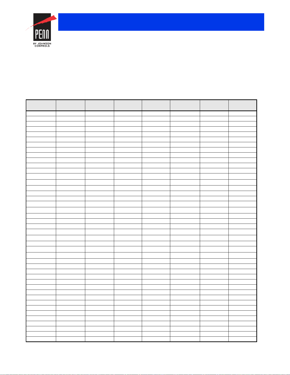
Repair and Replacement Information
If a V43/V243 Pressure-Actuated Water-Regulating Valve fails to operate within its specifications, replacement sensing elements, internal
parts, and diaphragms are available for valve repair.
To obtain replacement parts, kits, instructions, and details, contact your nearest Johnson Controls® distributor at
http://cgproducts.johnsoncontrols.com/dist_locate/locateDIST.asp.
For replacement parts, see Repair Parts and Parts Kits.
Repair Parts (Part 1 of 2)
Model Diaphragm
Kit
V43AS-1C DPM18A-600R DSC16A-600R STT19A-602R SCN10A-600R ROD18A-600R SEP88A-600R DBK11A-600R
V43AS-2C DPM18A-600R DSC16A-600R STT19A-602R SCN10A-600R ROD18A-600R SEP88A-601R DBK11A-600R
V43AS-5C DPM18A-600R DSC16A-600R STT19A-602R SCN10A-600R ROD18A-600R SEP87A-600R DBK11A-600R
V43AT-1C DPM18A-601R DSC16A-601R STT19A-603R SCN10A-600R ROD18A-601R SEP88A-600R DBK11A-601R
V43AT-2C DPM18A-601R DSC16A-601R STT19A-603R SCN10A-600R ROD18A-601R SEP88A-601R DBK11A-601R
V43AT-5C DPM18A-601R DSC16A-601R STT19A-603R SCN10A-600R ROD18A-601R SEP87A-600R DBK11A-601R
V43AV-1C DPM18A-602R DSC16A-602R STT19A-606R SCN10A-600R ROD18A-601R SEP88A-600R DBK11A-602R
V43AV-2C DPM18A-602R DSC16A-602R STT19A-606R SCN10A-600R ROD18A-601R SEP88A-601R DBK11A-602R
V43AV-5C DPM18A-602R DSC16A-602R STT19A-606R SCN10A-600R ROD18A-601R SEP87A-600R DBK11A-602R
V43AW-1C DPM18A-603R DSC16A-603R STT19A-608R SCN10A-600R ROD18A-602R SEP88A-600R DBK11A-603R
V43AW-2C DPM18A-603R DSC16A-603R STT19A-608R SCN10A-600R ROD18A-602R SEP88A-601R DBK11A-603R
V43AW-5C DPM18A-603R DSC16A-603R STT19A-608R SCN10A-600R ROD18A-602R SEP87A-600R DBK11A-603R
1
V43BS-1C
V43BS-2C
V43BS-3C DPM18A-600R DSC16A-600R STT19A-600R SCN10A-601R ROD18A-602R SEP88A-600R DBK10A-600R
V43BS-6C DPM18A-600R DSC16A-600R STT19A-600R SCN10A-601R ROD18A-602R SEP88A-600R DBK10A-600R
V43BS-7C DPM18A-600R DSC16A-600R STT19A-600R SCN10A-601R ROD18A-602R SEP88A-601R DBK10A-600R
V43BT-1C
V43BT-2C
V43BT-3C DPM18A-601R DSC16A-601R STT19A-605R SCN10A-601R ROD18A-603R SEP88A-600R DBK10A-602R
V43BT-6C DPM18A-601R DSC16A-601R STT19A-605R SCN10A-601R ROD18A-603R SEP88A-600R DBK10A-602R
V43BT-7C DPM18A-601R DSC16A-601R STT19A-605R SCN10A-601R ROD18A-603R SEP88A-601R DBK10A-602R
V43BV-1C
V43BV-2C
V43BV-4C DPM18A-602R DSC16A-602R STT19A-607R SCN10A-601R ROD18A-603R SEP88A-600R DBK10A-601R
V43BV-5C
V43BV-6C
V43BV-7C DPM18A-602R DSC16A-602R STT19A-607R SCN10A-601R ROD18A-603R SEP88A-601R DBK10A-601R
V43BV-8C DPM18A-602R DSC16A-602R STT19A-607R SCN10A-601R ROD18A-603R SEP88A-600R DBK10A-601R
V43BV-9C DPM18A-602R DSC16A-602R STT19A-607R SCN10A-601R ROD18A-603R SEP88A-601R DBK10A-601R
V43BV-10C DPM18A-602R DSC16A-602R STT19A-607R SCN10A-601R ROD18A-603R SEP88A-600R DBK10A-601R
V43BW-1C DPM18A-603R DSC16A-603R STT19A-609R SCN10A-601R ROD18A-602R SEP88A-600R DBK10A-603R
V43BW-2C DPM18A-603R DSC16A-603R STT19A-609R SCN10A-601R ROD18A-602R SEP88A-601R DBK10A-603R
V43BW-5C DPM18A-603R DSC16A-603R STT19A-609R SCN10A-601R ROD18A-602R SEP88A-600R DBK10A-603R
V43BW-6C DPM18A-603R DSC16A-603R STT19A-609R SCN10A-601R ROD18A-602R SEP88A-601R DBK10A-603R
V43BW-7C DPM18A-603R DSC16A-603R STT19A-609R SCN10A-601R ROD18A-602R SEP88A-600R DBK10A-603R
V43CS-1C DPM18A-600R DSC16A-600R STT19A-600R SCN10A-601R ROD18A-602R SEP88A-600R DBK10A-600R
V43CS-2C DPM18A-600R DSC16A-600R STT19A-600R SCN10A-601R ROD18A-602R SEP88A-600R DBK10A-600R
V43CS-3C DPM18A-600R DSC16A-600R STT19A-600R SCN10A-601R ROD18A-604R SEP88A-600R DBK10A-600R
V43CT-1C DPM18A-601R DSC16A-601R STT19A-605R SCN10A-601R ROD18A-603R SEP88A-600R DBK10A-602R
V43CT-2C DPM18A-601R DSC16A-601R STT19A-605R SCN10A-601R ROD18A-603R SEP86A-600R DBK10A-602R
V43CV-1C DPM18A-602R DSC16A-602R STT19A-607R SCN10A-601R ROD18A-603R SEP86A-600R DBK10A-601R
V43CV-2C DPM18A-602R DSC16A-602R STT19A-607R SCN10A-601R ROD18A-603R SEP88A-600R DBK10A-601R
DPM18A-600R DSC16A-600R STT19A-602R SCN10A-601R
1
DPM18A-600R DSC16A-600R STT19A-602R SCN10A-601R ROD18A-602R
1
DPM18A-601R DSC16A-601R STT19A-603R
1
DPM18A-601R DSC16A-601R STT19A-603R SCN10A-601R ROD18A-603R
1
DPM18A-602R
1
DPM18A-602R DSC16A-602R STT19A-606R SCN10A-601R ROD18A-603R
1
DPM18A-602R DSC16A-602R
1
DPM18A-602R DSC16A-602R STT19A-606R SCN10A-601R ROD18A-603R
Seat Disc and
Diaphragm Kit
DSC16A-602R
Seat Repair
Kit
STT19A-606R
STT19A-606R
Screen
Repair Kit
SCN10A-601R
SCN10A-601R ROD18A-603R
SCN10A-601R ROD18A-603R SEP88A-600R
Push Rod
1
Kit
ROD18A-602R
ROD18A-603R SEP88A-600R DBK11A-601R
Sensing
Element Kit
SEP88A-600R DBK11A-600R
SEP88A-601R
SEP88A-601R
SEP88A-600R DBK11A-602R
SEP88A-601R
SEP88A-601R
Disc Body
Kit
DBK11A-600R
DBK11A-601R
DBK11A-602R
DBK11A-602R
DBK11A-602R
The performance specifications are no minal and co nform t o acceptab le ind ustry standar ds. For appl ications at condition s beyond these specifica tions, consult th
Johnson Controls, Inc. shall not be liable for damages resulting from misapplication or misuse of its products. © 2015 Johnson Controls, Inc.
R-147
Page 4

The following valves, manufactured after date code 8702, contain monel interior trim. Order replacement kits as listed in Repair Parts or
V43xx and V243xx Series Repair Parts Kits Technical Bulletin (LIT-121690).
Valves and Valve Accessories
V43/V243 Series Pressure-Actuated Water-Regulating Valves (Continued)
Repair Parts (Part 2 of 2)
Model Diaphragm
Kit
V243GS-1C DPM18A-600R DSC16A-600R STT19A-602R SCN10A-600R ROD18A-600R SEP90A-600R DBK11A-600R
V243GT-1C DPM18A-601R DSC16A-601R STT19A-603R SCN10A-600R ROD18A-601R SEP90A-600R DBK11A-601R
V243GV-1C DPM18A-602R DSC16A-602R STT19A-606R SCN10A-600R ROD18A-601R SEP90A-600R DBK11A-602R
V243GW-1C DPM18A-603R DSC16A-603R STT19A-608R SCN10A-600R ROD18A-600R SEP90A-600R DBK11A-603R
V243HS-1C DPM18A-600R DSC16A-600R STT19A-600R SCN10A-601R ROD18A-602R SEP90A-600R DBK10A-600R
V243HT-1C DPM18A-601R DSC16A-601R STT19A-605R SCN10A-601R ROD18A-603R SEP90A-600R DBK10A-601R
V243HV-1C DPM18A-602R DSC16A-602R STT19A-607R SCN10A-601R ROD18A-603R SEP90A-600R DBK10A-602R
V243HW-1C DPM18A-603R DSC16A-603R STT19A-609R SCN10A-601R ROD18A-602R SEP90A-600R DPK10A-603R
1. Replacement push rod kit requires a seat repair kit and/or a diaphragm kit when replaced.
Parts Kits
Parts Kits
Valve Model Order Parts Kits for:
V43BS-1C V43BS-6C
V43BS-2C V43BS-7C
V43BT-1C V43BT-6C
V43BT-2C V43BT-7C
V43BV-1C V43BV-10C
V43BV-2C V43BV-7C
V43BV-5C V43BV-10C
V43BV-6C V43BV-9C
Seat Disc and
Diaphragm Kit
Seat Repair
Kit
Screen
Repair Kit
Push Rod
1
Kit
Sensing
Element Kit
Disc Body
Kit
Dimensions
Symbol 2 Inch 2-1/2 Inch 3 Inch 4 Inch
1
A
B 7-1/2 in. (191 mm) 8 in. (203 mm) 9 in. (229 mm) 10-3/4 in. (273 mm)
C 4-3/4 in. (121 mm) 5-1/2 in. (140 mm) 6 in. (152 mm) 7-1/2 in. (191 mm)
D 6 in. (152 mm) 7 in. (178 mm) 7-1/2 in. (191 mm) 9 in. (229 mm)
E 2-1/8 in. (54 mm) 2-5/8 in. (67 mm) 3-1/8 in. (80 mm) 4-1/8 in. (105 mm)
2
F
3
F
G 3/4 in. (19 mm) Diameter (Four) 3/4 in. (19 mm) Diameter (Four) 3/4 in. (19 mm) Diameter (Four) 3/4 in. (19 mm) Diameter (Eight)
H 3-5/8 in. (92 mm) 3-15/16 in. (100 mm) 4-1/4 in. (108 mm) 5- 1/16 in. (128 mm)
1. Flange face to flange face.
2. These are the measurements for the V43 valves.
3. These are the measurements for the V243 valves.
9-1/2 in. (241 mm) 10-3/4 in.(273 mm) 11-3/4 in. (298 mm) 14 in. (356 mm)
15-1/4 in. (387 mm) 15-9/16 in. (395 mm) 16-9/16 in. (421 mm) 18-7/32 in. (462 mm)
15-29/32 in. (404 mm) 16-7/32 in. (412 mm) 17-7/32 in. (437 mm) 18-7/8 in. (479 mm)
The performance specifications are no minal and co nform t o acceptab le ind ustry standar ds. For appl ications at condition s beyond these specifica tions, consult th
Johnson Controls, Inc. shall not be liable for damages resulting from misapplication or misuse of its products. © 2015 Johnson Controls, Inc.
R-148
Page 5

V43/V243 Pressure Actuated Water Regulating Valves Dimensions
F
H
DDD
G
G
G
B
A
C
E
E
E
Six- and Eight-
Flange Hole Configurations
FIG:Dimensions
404050
30
30
20
20
10
10
0
0
Refrigerant Head Pressure Rise Above
Valve Opening Point (psig)
10
50
100 150 200 250 300 350 400 450
20 30 50
Water Flow (GPM)
Water Pressure Available Across Valve (psi)
CAPACITY CHART FOR 2 in. VALVE
Medium Pres sure
Refrigerants
Low Pressure
Refrigerants
40
30
20
10
0
10
100 200
300 400 500 600
700
800
900
20
30
50
Water Pressure Available Across Valve (psi)
CAPACITY CHART FOR 3 in. VALVE
40
50
30
20
10
0
Refrigerant Head Pressure Rise Above
Valve Opening Point (psig)
Water Flow (GPM)
Medium Press u re
Refrigerants
Low Pressure
Refrigerants
40
30
20
10
0
10
50
100 150 200 250 300 350 400 450
20 30 50
Water Pressure A vailable Across Valve (psi)
40
50
30
20
10
0
Refrigera nt H ead Pr ess ur e Rise Above
Valve Op ening Poi n t (psig)
Water Flow (GPM)
CAPACITY CHART FOR 2-1/2 in. VALVE
Medium Pressure
Refrigerants
Low Pre s s ure
Refrigerants
40
30
20
10
0
5
150 300
450 600 750 900
1050 1200 1350
10 20 30
50
Water Pressure Available Across Valve (psi)
CAPACITY CHART FOR 4 in. VALVE
40
50
30
20
10
0
Refrigerant Head Pressure Rise Above
Valve Opening Point (psig)
Water Flow (GPM)
Medium Pressure
Refrigerants
Low Pressure
Refrigerants
Valves and Valve Accessories
V43/V243 Series Pressure-Actuated Water-Regulating Valves (Continued)
V43 Capacity Flow Charts
The performance specifications are no minal and co nform t o acceptab le ind ustry standar ds. For appl ications at condition s beyond these specifica tions, consult th
Johnson Controls, Inc. shall not be liable for damages resulting from misapplication or misuse of its products. © 2015 Johnson Controls, Inc.
R-149
Page 6

60
40
20
0
10
50 100 150 200 250 300 350 400 450
20 30 50
Water Pressure Available Across Valve (psi)
Refrigerant Head Pressure Rise Above
Valve Opening Point (psig)
Water Flow (GPM)
CAPACITY CHART FOR 2 in. VALVE
2 5 14.5 25 40 60
60
40
20
0
10
100 200 300 400 500 600 700 800 900
20 30 50
Water Pressure A vailable Across Valve (psi)
Refrigerant Head Pressure Rise Above
Valve Op en ing P oi nt ( psig)
Water Flow (GPM)
CAPACITY CHART FOR 2-1/2 in. VALVE
2 5 14.5 25 40 60
60
40
20
0
10
100 200 300 400 500 600 700 800 900
20 30 50
Water Pressure A vailable Across Valve (psi)
Refrigerant Head Press u re Rise Above
Valve Opening Point (psig)
Water Flow (GPM)
CAPACITY CHART FOR 4 in. VALVE
2 5 14.5 25 40 60
1000 1100
1200
1300
60
40
20
0
10
100 200
300
400
500
600
700
800
900
20 30 50
Water Pr es sure A vai lab le A cro ss V a lv e (psi)
Refrigerant Head Pressure Rise Above
V a l v e O pening Point (psig)
Water Flow (GPM)
CAPACITY CHART FOR 3 in. VALVE
2 5 14.5 25 40 60
V43/V243 Series Pressure-Actuated Water-Regulating Valves (Continued)
V243 Capacity Flow Charts
Valves and Valve Accessories
Technical Specifications
Maximum Water Supply Pressure 150 psig (1,034 kPa)
V43 Maximum Head Pressure 300 psig (2,068 kPa)
V243 Maximum Head Pressure 630 psig (4,344 kPa)
Head Pressure Range (Opening Points) V43 Low Pressure
Factory Settings
Maximum Water Supply Temperature 160°F (71°C)
Valve Body Material Commercial Cast iron
Internal Parts Material Commercial Brass
Seat Material Pilot Monel
Seat Disc Material Buna N™
Packing – Bellows Assembly Brass stem, stainless steel spring, synthetic rubber boot
Pressure Connection Refrigerant Side Non-Corrosive 1/4 in. SAE External Flare
1. Factory opening setpoint for the valve is adjustable.
The performance specifications are no minal and co nform t o acceptab le ind ustry standar ds. For appl ications at condition s beyond these specifica tions, consult th
Johnson Controls, Inc. shall not be liable for damages resulting from misapplication or misuse of its products. © 2015 Johnson Controls, Inc.
1
V43/V243 Pressure-Actuated Water-Regulating Valves
Refrigerants
R-134A – 70 to 150 psig (482 to 1,034 kPa)
Medium Pressure
Refrigerants
R-22, R-502, R404A – 160 to 260 psig (1,103 to 1,793 kPa)
Ammonia 160 to 260 psig (1,103 to 1,793 kPa)
V243 High Pressure 200 to 400 psig (1,379 to 2,758 kPa)
V43 Low Pressure
90 psig (621 kPa)
Refrigerants
Medium Pressure
Refrigerants
180 psig (1,241 kPa)
Ammonia 180 psig (1,241 kPa)
V243 High Pressure 200 psig (1,379 kPa)
Maritime Red brass
Maritime Bronze, Monel
Main Valve Commercial – Bronze, Maritime – Monel
Ammonia 1/4 in. FNPT
R-150
 Loading...