

Page 1
V246 Series Water-Regulating Valve
Valves and Valve Accessories
Code No. LIT-1900575
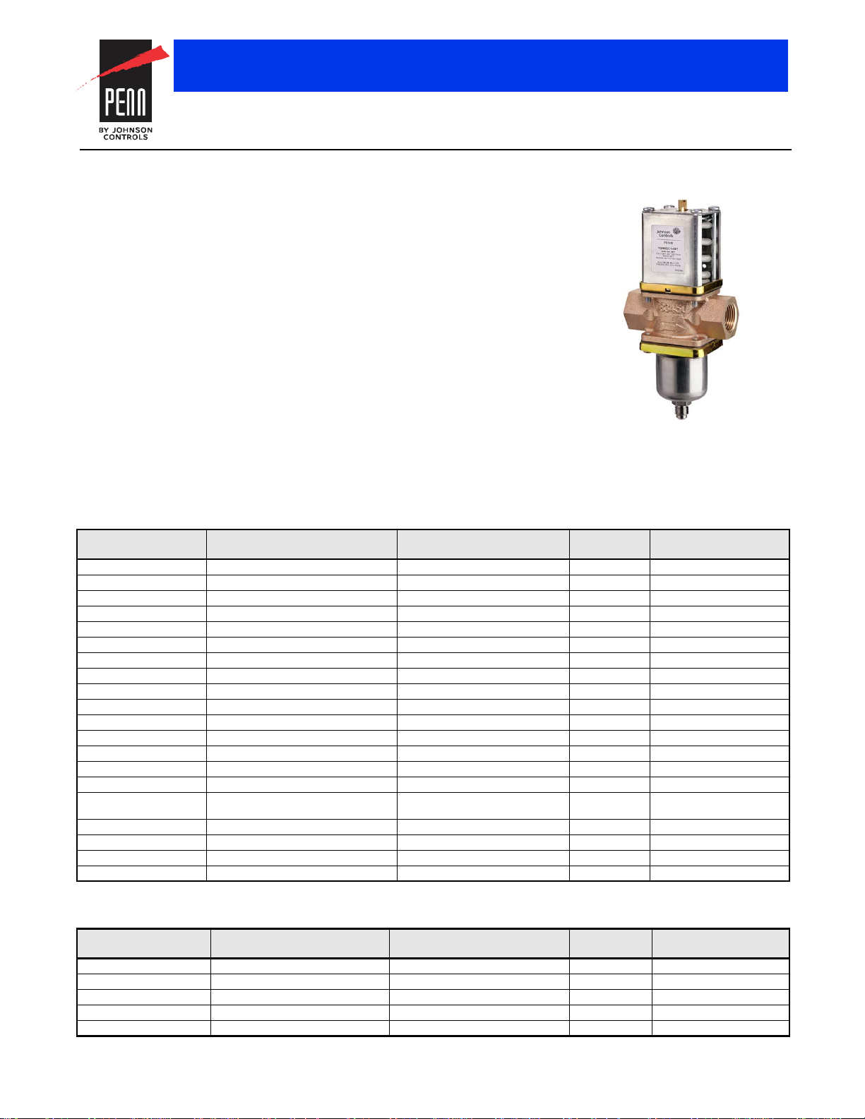
V246 Series Two-Way Pressure-Actuated Water-Regulating Valves
for High-Pressure Refrigerants
Description
The V246 Series Two-Way
Pressure-Actuated Water-Regulating Valves
for High-Pressure Refrigerants come in two
types of control action: direct acting and
reverse acting. V246 valves regulate water
flow to control refrigerant head pressure in
systems with water-cooled condensers.
The V246 Series Valves are available in 3/8 in.
through 2 in. sizes and have a maximum
allowable water pressure of 150 psig
(10.3 bar). Direct acting V246 valves have an
adjustable opening point in a refrigerant
pressure range of 200 to 400 psi
(13.8 to 27.6 bar), and reverse acting valves
have a range of 135 to 300 psi
(9.3 to 20.7 bar). V246 valves
may be used
with standard non-corrosive refrigerants.
Maritime models, which have nickel copper
(Monel®) internal parts, are available for
applications where the media may be
corrosive to the internal parts.
Selection Charts
North American Standard Production Models
Product Code Number Construction Valve Size and Connection Element Style Shipping Weight,
V246GA1-001C Direct Acting1, Commercial
V246GB1-001C Direct Acting
V246GC1-001C Direct Acting
V246GD1-001C Direct Acting
V246GE1-001C Direct Acting
V246GM1-001C Direct Acting
V246GR1-001C Direct Acting
V246GS1-001C Direct Acting
V246HA1-001C Direct Acting
V246HB1-001C Direct Acting
V246HC1-001C Direct Acting
V246HD1-001C Direct Acting
V246HE1-001C Direct Acting
V246HR1-001C Direct Acting
V246HS1-001C Direct Acting
V246KA1-001C Direct Acting
V246NA1-001C Reverse Acting
V246NB1-001C Reverse Acting
V246NC1-001C Reverse Acting
V246ND1-001C Reverse Acting
1. The range is 200 to 400 psi (13.8 to 27.6 bar).
2. The range is 135 to 300 psi (9.3 to 20.7 bar).
Low Flow
European Standard Production Models (Part 1 of 2)
Product Code Number Construction Valve Size and Connection Element Style Shipping Weight,
V246GA1A001C Direct Acting, Commercial 3/8 in. BSPP Screw, ISO228 Style 5 0.8 (1.8)
V246GB1A001C Direct Acting, Commercial 1/2 in. BSPP Screw, ISO228 Style 5 1.4 (3.0)
V246GC1A001C Direct Acting, Commercial 3/4 in. BSPP Screw, ISO228 Style 5 1.7 (3.7)
V246GD1B001C Direct Acting, Commercial 1 in. BSPT Screw, ISO 7 Style 5 4.2 (9.3)
V246GE1B001C Direct Acting, Commercial 1-1/4 in. BSPT Screw, ISO 7 Style 5 4.5 (10)
The performance specifications are nomina l and con form to accep table ind ustry stand ards. For applicati ons at con ditions be yond these specification s, consult th
Johnson Controls, Inc. shall not be liable for damages resulting from misapplication or misuse of its products. © 2015 Johnson Controls, Inc.
1
, Commercial 1/2 in. NPT Screw Style 5 3.0 (1.4)
1
, Commercial 3/4 in. NPT Screw Style 5 3.7 (1.7)
1
, Commercial 1 in. NPT Screw Style 5 9.3 (4.2)
1
, Commercial 1-1/4 in. NPT Screw Style 5 10 (4.5)
1
, Commercial 1-1/4 in. Union Sweat Style 5 10 (4.5)
1
, Commercial 1-1/2 in. Flange Style 5 13.6 (6.2)
1
, Commercial 2 in. Flange Style 5 27 (12.3)
1
, Maritime 3/8 in. NPT Screw Style 5 1.8 (0.8)
1
, Maritime 1/2 in. NPT Screw Style 5 3.0 (1.4)
1
, Maritime 3/4 in. NPT Screw Style 5 4.3 (2.0)
1
, Maritime 1 in. NPT Screw Style 5 9.5 (4.3)
1
, Maritime 1-1/4 in. NPT Screw Style 5 10.3 (4.7)
1
, Maritime 1-1/2 in. ASME Flange Style 5 13.6 (6.2)
1
, Maritime 2 in. ASME Flange Style 5 27 (12.3)
1
, Commercial,
Refer to the V246 Series 2-Way
Pressure-Actuated Water-Regulating Valves
for High-Pressure Refrigerants Product
Bulletin (LIT-12011514) for important product
application information.
Features
• no close fitting or sliding parts in water
passages
• accessible range spring
• take-apart construction
• pressure-balanced design
• corrosion-resistant material for internal
parts
Repair Information
If the V246 Series Two-Way
Pressure-Actuated Water-Regulating Valve
for High Pressure Refrigerants fails to operate
within its specifications, refer to the V246
Series Two-Way Pressure-Actuated
Water-Regulating Valves for High Pressure
Refrigerants Product Bulletin (LIT-12011514)
for a list of repair parts available.
lb (kg)
3/8 in. NPT Screw Style 5 1.8 (0.8)
3/8 in. NPT Screw Style 5 1.8 (0.8)
2
, Commercial
2
, Commercial 1/2 in. NPT Screw Style 5 3.0 (1.4)
2
, Commercial 3/4 in. NPT Screw Style 5 3.7 (1.7)
2
, Commercial 1 in. NPT Screw Style 5 9.3 (4.2)
3/8 in. NPT Screw Style 5 1.8 (0.8)
kg (lb)
R-171
Page 2
Flow Required
Flow =
(Temp. - Temp. )
Outlet Inlet
FIG:flw_e qn
Valve Opening Pressure
FIG:eqn_
opn_prs
P = P +10 psi (0.7 bar)
OPEN CLOSE
Refrigerant Head Pressure Rise
FIG
P = P - P
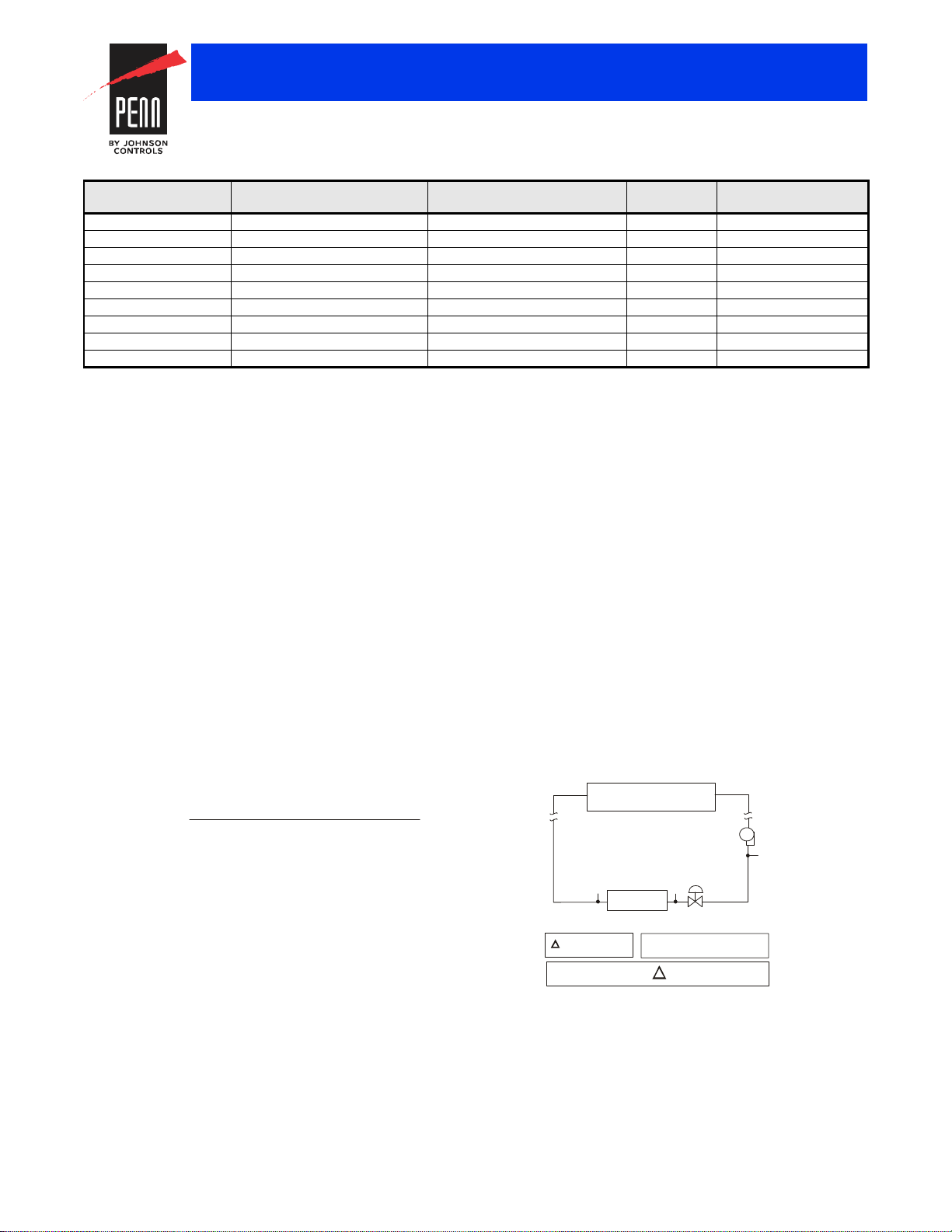
Available Water Pressure
Cooling Tower
P
1
P
2
P
Loss 2
2-Way
Valve
P
IN
COND
P
P
1P2
=
-
P
P
P
=
+
+ ...
FIG:2wy_prs s_dr
Valves and Valve Accessories
V246 Series Two-Way Pressure-Actuated Water-Regulating Valves for
High-Pressure Refrigerants (Continued)
European Standard Production Models (Part 2 of 2)
Product Code Number Construction Valve Size and Connection Element Style Shipping Weight,
kg (lb)
V246GR1B001C Direct Acting, Commercial 1-1/2 in. Flange, DIN2533 Style 5 6.2 (13.6)
V246GS1B001C Direct Acting, Commercial 2 in. Flange, DIN2533 Style 5 12.3 (27)
V246HA1B001C Direct Acting, Maritime 3/8 in. BSPP Screw, ISO228 Style 5 0.8 (1.8)
V246HB1B001C Direct Acting, Maritime 1/2 in. BSPP Screw, ISO228 Style 5 1.4 (3.0)
V246HC1B001C Direct Acting, Maritime 3/4 in. BSPP Screw, ISO228 Style 5 2.0 (4.3)
V246HD1B001C Direct Acting, Maritime 1 in. BSPP Screw, ISO 228 Style 5 4.3 (9.5)
V246HE1B001C Direct Acting, Maritime 1-1/4 in. BSPP Screw, ISO 228 Style 5 4.7 (10.3)
V246HR1B001C Direct Acting, Maritime 1-1/2 in. Flange, DIN86021 Styl e 5 6.2 (13.6)
V246HS1B001C Direct Acting, Maritime 2 in. Flange, DIN86021 Style 5 12.3 (27)
Valve Sizing Information
.
Each application is unique and requires specific engineering data to
properly size and design a system to fulfill the appropriate
requirements. Typically, a valve is replaced with another valve of the
same size in a properly sized and engineered system. In North
America, contact Johnson Controls/PENN® Refrigeration Application
Engineering at 1-800-275-5676 to obtain specific engineering data. In
other areas, contact the local Johnson Controls® sales office to obtain
specific engineering data.
To make a rough field estimate of the size of valve for an application,
c. From the Pressure-Temperature Chart for the refrigerant
selected, read the Refrigerant Condensing Pressure (P
(operating head pressure) corresponding to the selected
condensing temperature.
d. Subtract the Valve Opening Pressure from the Refrigerant
Condensing Pressure. This gives the head pressure rise.
find the valve size needed by locating a point on a flow chart that
satisfies these requirements:
• water flow required by the condenser (Flow)
• refrigerant head pressure rise (P
• available water pressure (P
AVAIL
RISE
)
)
Follow these steps, and use the information obtained to locate a point
on one of the flowcharts that satisfies all three steps.
1. Take the water flow required by the condenser (Flow) from
information provided by the manufacturer of the condensing unit. If
the manufacturer’s information is unavailable, use the following
information to make a rough approximation of water flow in gallons
per minute (gpm) [cubic meters per hour (m
3
/hr)]:
• System Capacity (Tons of Refrigeration)
Inlet
Outlet
)
)
• Outlet Water Temperature (Temp.
• Inlet Water Temperature (Temp.
Calculate the flow using the following formula:
3. Determine the available water pressure to the valve (P
the following steps. This is the actual water pressure available to
force water through the valve.
a. Determine the inlet pressure (P
from city water mains, pumps, or other sources.
b. Pressure drop through condenser (P
water pressure between the condenser inlet and the condenser
outlet. Obtain this information from the condenser manufacturer.
c. Estimate or calculate the pressure drop through all associated
piping (P
d. Subtract the P
RISE COND OPEN
).
LOSS
COND
and P
:eqn_hd_prs sr_rs
). This is the water pressure
IN
) is the difference in
COND
from PIN. The result is P
LOSS
p
AVAIL
Tons of Refrigeration x 30
Pump
COND
) using
AVAIL
)
.
Note: If the outlet temperature is unknown, assume it to be 10F
(6C) above the inlet temperature.
2. Determine refrigerant head pressure rise above the valve opening
point (P
the following steps:
) using the Refrigerant Head Pressure Rise figure and
RISE
a. The Valve Closing Pressure (P
refrigerant pressure at the highest ambient temperature the
refrigeration equipment experiences in the Off cycle. Use a
Pressure-Temperature Chart for the refrigerant selected to find
this pressure.
b. To approximate the Valve Opening Pressure (P
about 10 psi (0.7 bar) to the Valve Closing Pressure.
Note: Add about 20 psi (1.4 bar) for 3/8 in. valves.
The performance specifications are no minal and co nform t o acceptab le ind ustry standar ds. For appl ications at condition s beyond these specifica tions, consult th
Johnson Controls, Inc. shall not be liable for damages resulting from misapplication or misuse of its products. © 2015 Johnson Controls, Inc.
) is equal to the
CLOSE
OPEN
), add
Condenser
Loss 1
LOSS
P= P- (P+ P)
AVAIL IN COND LOSS
Loss 2
P
Loss 1
4. Select the proper valve size from the flowcharts by locating a point
on a chart that satisfies the flow, the head pressure rise above
opening point, and the pressure drop across the valve.
Metric Conversions
Use these equations to convert between U.S. and S.I. units.
3
•1 dm
• 1 bar = 100 kPa = 0.1 MPa 1.02 kg/cm
/s = 3.6 m3/h = 15.9 U.S. gal. /min. = 13.2 U.K. gal. /min.
2
= 0.987 atm 14.5 psi
R-172
Page 3
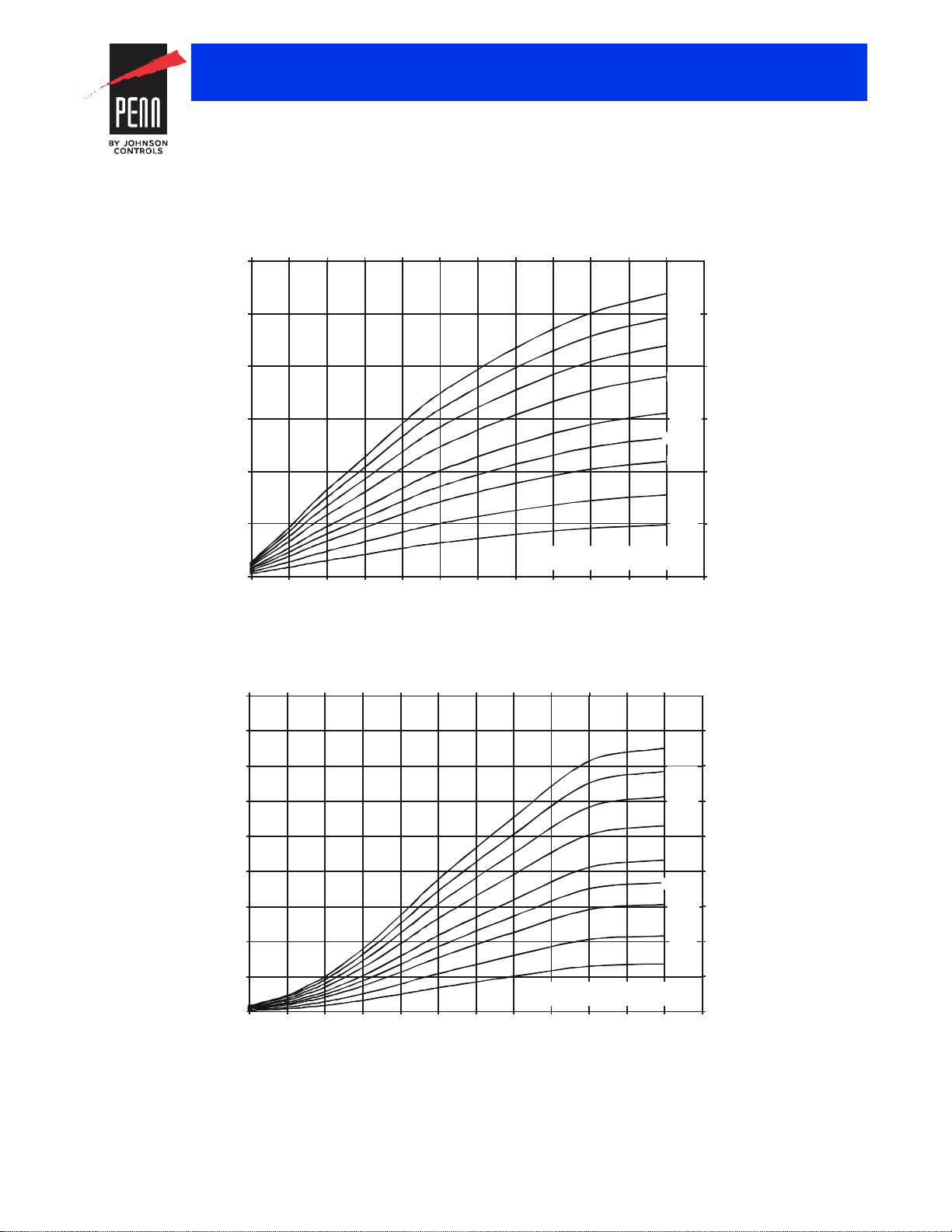
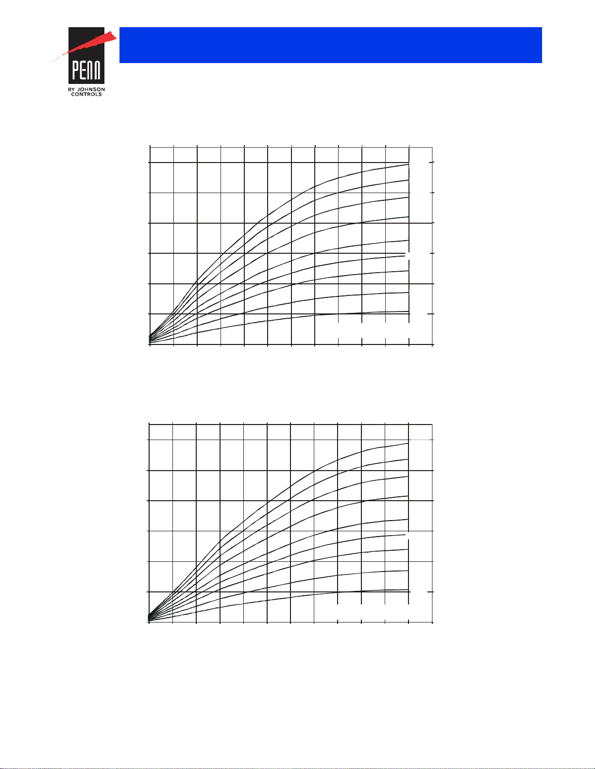
3/8 in. Direct Acting Low-Flow Valve Flowchart
0.7 1.4 2.1 2.8 3.5 4.2 4.9 5.5 6.2 6.9 7.6 8.3
0.0
0.1
0.2
0.3
0.5
0.6
0.0
0.5
1.0
1.5
2.0
2.5
3.0
10 20 30 40 50 60 70 80 90 100 110 120 130
Refrigerant Head Pressure Above Opening P
Rise
( psig )
10 (0.7)
5 (0.3)2 (0.1)
P
Avail
Pressure Drop Through Valve
psig(bar)
40 (2.8)
30 (2.1)
50 (3.4)
60 (4.1)
14.5 (1.0)
20 (1.4)
FIG:V246_3.8 in. Low graph
Refrigerant Head Pressure Above Opening P
Rise
( bar )
Flow
(gpm)
Flow
(m /hr)
3
3/8 in. Direct Acting Valve Flowchart
0.7 1.4 2.1 2.8 3.5 4.2 4.9 5.5 6.2 6.9 7.6 8.3
0.0
0.5
0.9
1.4
1.8
2.3
2.7
3.2
3.6
0
2
4
6
8
10
12
14
16
18
10 20 30 40 50 60 70 80 90 100 1 10 120 130
Refrigerant Head Pressure Above Opening P
Rise
( psig )
10 (0.7)
5 (0.3)
2 (0.1)
P
Avail
Pressure Drop Through Valve
psig (bar)
40 (2.8)
30 (2.1)
50 (3.4)
60 (4.1)
14.5 (1.0)
20 (1.4)
FIG:V246_3.8 in. graph
Flow
(gpm)
Flow
(m /hr)
3
Refrigerant Head Pressure Above Opening P
Rise
( bar )
Valves and Valve Accessories
V246 Series Two-Way Pressure-Actuated Water-Regulating Valves for
High-Pressure Refrigerants (Continued)
V246 Flowcharts
The maximum recommended differential water pressure across a valve is 60 psig (4.1 bar).
The performance specifications are no minal and co nform t o acceptab le ind ustry standar ds. For appl ications at condition s beyond these specifica tions, consult th
Johnson Controls, Inc. shall not be liable for damages resulting from misapplication or misuse of its products. © 2015 Johnson Controls, Inc.
R-173
Page 4
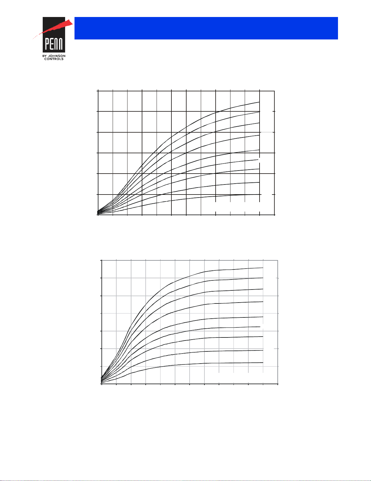
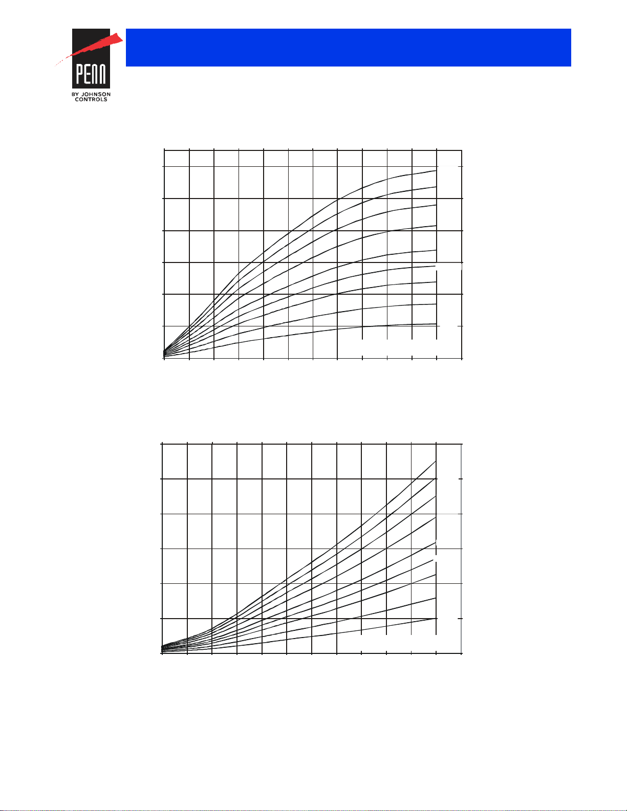
1/2 in. Direct Acting Valve Flowchart
0.7 1.4 2.1 2.8 3.5 4.2 4.9 5.5 6.2 6.9 7.6 8.3
0.0
1.1
2.3
3.4
4.5
5.7
0
5
10
15
20
25
30
10 20 30 40 50 60 70 80 90 100 110 120 130
Refrigerant Head Pressure Above Opening P
Rise
( psig )
10 (0.7)
5 (0.3)
2 (0.1)
P
Avail
Pressure Drop Through Valve
psig(bar)
40 (2.8)
30 (2.1)
50 (3.4)
60 (4.1)
14.5 (1.0)
20 (1.4)
FIG:V246_0.5 in. graph
Refrigerant Head Pressure Above Opening P
Rise
( bar )
Flow
(gpm)
Flow
(m /hr)
3
3/4 in. Direct Acting Valve Flowchart
0.7 1.4 2.1 2.8 3.5 4.2 4.9 5.5 6.2 6.9 7.6 8.3
0.0
1.1
2.3
3.4
4.5
5.7
6.8
0
5
10
15
20
25
30
35
10 20 30 40 50 60 70 80 90 100 110 120 130
Refrigerant Head Pressure Above Opening P
Rise
( psig )
10 (0.7)
5 (0.3)
2 (0.1)
P
Avail
Pressure Drop Through Valve
psig (bar)
40 (2.8)
30 (2.1)
50 (3.4)
60 (4.1)
14.5 (1.0)
20 (1.4)
FIG:V246_0.75 in. graph
Refrigerant Head Pressure Abov e O pening P
Rise
( bar )
Flow
(gpm)
Flow
(m /hr)
3
Valves and Valve Accessories
V246 Series Two-Way Pressure-Actuated Water-Regulating Valves for
High-Pressure Refrigerants (Continued)
The performance specifications are no minal and co nform t o acceptab le ind ustry standar ds. For appl ications at condition s beyond these specifica tions, consult th
Johnson Controls, Inc. shall not be liable for damages resulting from misapplication or misuse of its products. © 2015 Johnson Controls, Inc.
R-174
Page 5
1 in. Direct Acting Valve Flowchart
0.7 1.4 2.1 2.8 3.5 4.2 4.9 5.5 6.2 6.9 7.6 8.3
0.0
2.3
4.5
6.8
9.1
11.4
13.6
0
10
20
30
40
50
60
10 20 30 40 50 60 70 80 90 100 110 120 130
Refrigerant Head Pressure Above Opening P
Rise
( psig )
10 (0.7)
5 (0.3)
2 (0.1)
P
Avail
Pressure Drop Through Valve
psig (bar)
40 (2.8)
30 (2.1)
50 (3.4)
60 (4.1)
14.5 (1.0)
20 (1.4)
FIG:V246_1.0 in. graph
Refrigerant Head Pressure Above Opening P
Rise
( bar )
Flow
(gpm)
Flow
(m /hr)
3
1-1/4 in. Direct Acting Valve Flowchart
0.7 1.4 2.1 2.8 3.5 4.2 4.9 5.5 6.2 6.9 7.6 8.3
0.0
4.5
9.1
13.6
18.2
22.7
27.3
0
20
40
60
80
100
120
10 20 30 40 50 60 70 80 90 100 110 120 130
Refrigerant Head Pressure Above Opening P
Rise
( psig )
10 (0.7)
5 (0.3)
2 (0.1)
P
Avail
Pressure Drop Through Valve
psig(bar)
40 (2.8)
30 (2.1)
50 (3.4)
60 (4.1)
14.5 (1.0)
20 (1.4)
FIG:V246_1.25 in. graph
Refrigerant Head Pressure Above Opening P
Rise
( bar )
Flow
(gpm)
Flow
(m /hr)
3
Valves and Valve Accessories
V246 Series Two-Way Pressure-Actuated Water-Regulating Valves for
High-Pressure Refrigerants (Continued)
The performance specifications are no minal and co nform t o acceptab le ind ustry standar ds. For appl ications at condition s beyond these specifica tions, consult th
Johnson Controls, Inc. shall not be liable for damages resulting from misapplication or misuse of its products. © 2015 Johnson Controls, Inc.
R-175
Page 6
1-1/2 in. Direct Acting Valve Flowchart
0.7 1.4 2.1 2.8 3.5 4.2 4.9 5.5 6.2 6.9 7.6 8.3
0.0
4.5
9.1
13.6
18.2
22.7
27.3
0
20
40
60
80
100
120
10 20 30 40 50 60 70 80 90 100 110 120 130
Refrigerant Head Pressure Above Opening P
Rise
( psig )
10 (0.7)
5 (0.3)
2 (0.1)
P
Avail
Pressure Drop Through
Valve psig(bar)
40 (2.8)
30 (2.1)
50 (3.4)
60 (4.1)
14.5 (1.0)
20 (1.4)
FIG:V246_1.5 in. graph
Refrigerant Head Pressure Above Opening P
Rise
( bar )
Flow
(gpm)
Flow
(m /hr)
3
2 in. Direct Acting Valve Flowchart
0.7 1.4 2.1 2.8 3.5 4.2 4.9 5.5 6.2 6.9 7.6 8.3
0.0
4.5
9.1
13.6
18.2
22.7
27.3
0
20
40
60
80
100
120
10 20 30 40 50 60 70 80 90 100 110 120 130
Refrigerant Head Pressure Above Opening P
Rise
( psig )
10 (0.7)
5 (0.3)
2 (0.1)
P
Avail
Pressure Drop Through Valve psi
(bar)
40 (2.8)
30 (2.1)
50 (3.4)
60 (4.1)
14.5 (1.0)
20 (1.4)
FIG:V246_2 in. graph
Refrigerant Head Pressure Above Opening P
Rise
( bar )
Flow
(gpm)
Flow
(m /hr)
3
Valves and Valve Accessories
V246 Series Two-Way Pressure-Actuated Water-Regulating Valves for
High-Pressure Refrigerants (Continued)
The performance specifications are no minal and co nform t o acceptab le ind ustry standar ds. For appl ications at condition s beyond these specifica tions, consult th
Johnson Controls, Inc. shall not be liable for damages resulting from misapplication or misuse of its products. © 2015 Johnson Controls, Inc.
R-176
Page 7
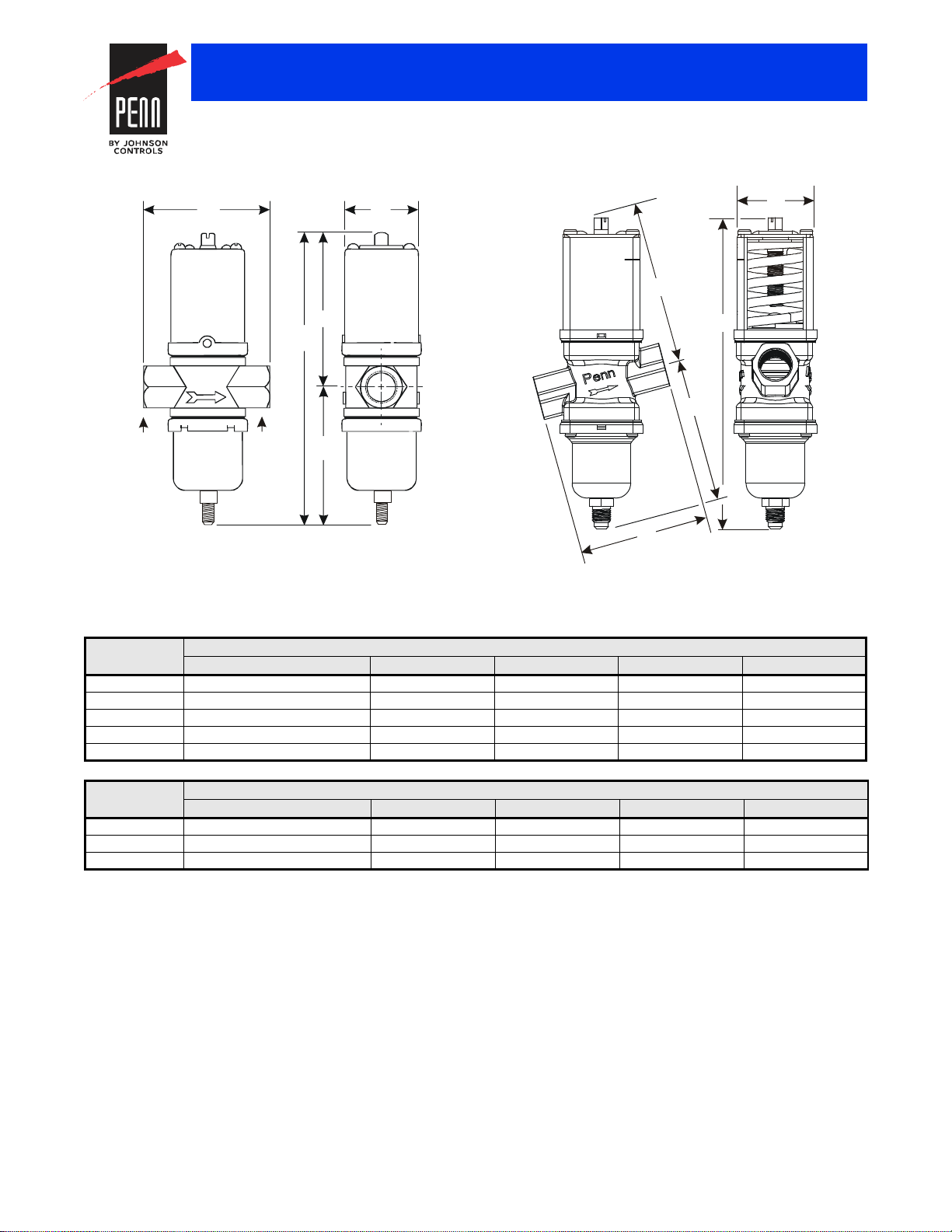
V246 Screw Connection Valves Dimensions
FIG:V246_thrdd
V246 Angle-Body Screw Connection Valves Dimensions
D
E
A
FIG:V24 6_anglbdy
Dimensions
Valves and Valve Accessories
V246 Series Two-Way Pressure-Actuated Water-Regulating Valves for
High-Pressure Refrigerants (Continued)
A
B
B
D
C
C
Port 1
Port 2
E
V246 Screw Connection Valves Dimensions
Valve Size Dimensions in Inches (Millimeters)
A B C D E
3/8 in. 2-5/8 (67) 1-5/8 (41) 6-1/2 (166) 3-1/2 (89) 3 (77)
1/2 in. 3-1/16 (78) 2 (51) 7-3/16 (182) 3-13/16 (96) 3-3/8 (86)
3/4 in. 3-3/8 (86) 2-3/16 (55) 8 (203) 4-3/16 (106) 3-13/16 (98)
1 in. 4-3/4 (121) 2-13/16 (71) 10-1/2 (267) 5-15/16 (151) 4-9/16 (116)
1-1/4 in. 4-3/4 (121) 2-13/16 (71) 10-7/8 (276) 6-1/8 (156) 4-3/4 (121)
V246 Angle-Body Screw Connection Valves Dimensions
Valve Size Dimensions in Inches (Millimeters)
A B C D E
3/8 in. 2-3/4 (70) 1-5/8 (41) 6-15/16 (176) 3-5/8 (92) 3-1/8 (80)
1/2 in. 3-1/8 (80) 2 (51) 7-1/2 (191) 3-7/8 (98) 3-1/2 (88)
3/4 in. 3-9/16 (90) 2-1/8 (55) 8-9/16 (217) 4-5/16 (1 10) 4 (101)
The performance specifications are no minal and co nform t o acceptab le ind ustry standar ds. For appl ications at condition s beyond these specifica tions, consult th
Johnson Controls, Inc. shall not be liable for damages resulting from misapplication or misuse of its products. © 2015 Johnson Controls, Inc.
R-177
Page 8

V246 Union Sweat Connection Valves Dimensions
E
D
C
A
Port 1
Port 2
FIG:V246_unnbdy
V246 Flange Valve Dimensions
FIG:flng_b dy
A
B
C
D
E
F
G
H
Valves and Valve Accessories
V246 Series Two-Way Pressure-Actuated Water-Regulating Valves for
High-Pressure Refrigerants (Continued)
B
V246 Union Sweat Connection Valves Dimensions
Valve Size Dimensions in Inches (Millimeters)
A B C D E
1-1/4 in. 4-3/4 (121) 2-13/16 (71) 10-7/8 (276) 6-1/8 (156) 4-3/4 (121)
The performance specifications are no minal and co nform t o acceptab le ind ustry standar ds. For appl ications at condition s beyond these specifica tions, consult th
Johnson Controls, Inc. shall not be liable for damages resulting from misapplication or misuse of its products. © 2015 Johnson Controls, Inc.
R-178
Page 9
Valves and Valve Accessories
V246 Series Two-Way Pressure-Actuated Water-Regulating Valves for
High-Pressure Refrigerants (Continued)
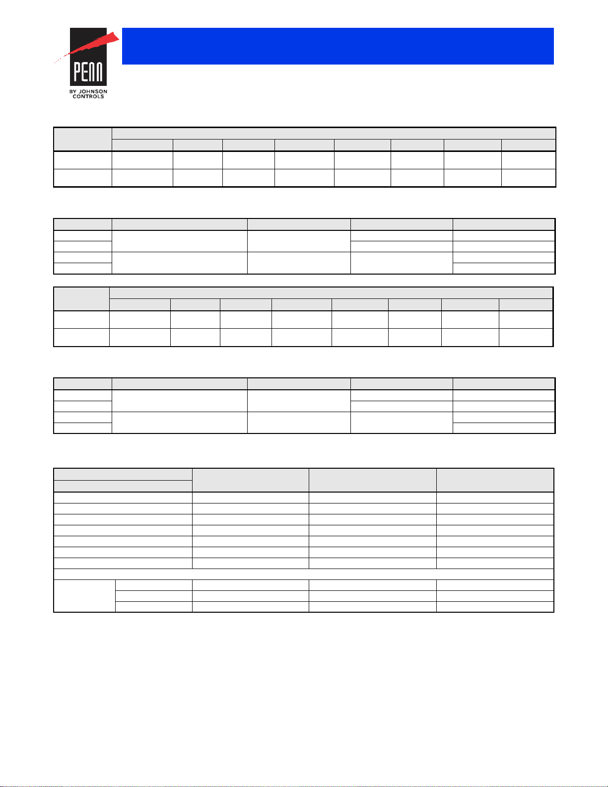
V246 Flange Valve, Commercial Service - Dimensions
Valve
Size
1-1/2 in. 5-5/16
2 in. 6-5/8
1. The dimensions on the European versions are 5-29/32 in. (150 mm).
2. The dimensions on the European versions are 6-1/2 in. (165 mm).
A B C D E F G H
(135)
(168)
9/16
(14)
5/8
(16)
V246 Flange Valve, Commercial Service - Flange Specifications
Valve Size Regional Version Number of Holes Hole Size Bolt Circle
1-1/2 in. North American 4 5/8 in. (16 mm) 3-7/8 in. (98 mm)
2 in. 3/4 in. (19 mm) 4-3/4 in. (121 mm)
1-1/2 in. European, DIN2533 Flanges 4 18 mm 110 mm
2 in. 125 mm
V246 Flange Valve, Maritime Service - Dimensions
Valve
Size
1-1/2 in. 5-5/16
2 in. 6-3/8
1. The dimensions on the European versions are 5-29/32 in. (150 mm).
2. The dimensions on the European versions are 6-1/2 in. (165 mm).
A B C D E F G H
(135)
(162)
9/16
(14)
5/8
(16)
6-1/8
(156)
7-1/8
(181)
V246 Flange Valve, Maritime Service - Flange Specifications
Valve Size Regional Version Number of Holes Hole Size Bolt Circle
1-1/2 in. North American 4 5/8 in. (16 mm) 3-7/8 in. (98 mm)
2 in. 3/4 in. (19 mm) 4-3/4 in. (121 mm)
1-1/2 in. European, DIN86021 Flanges 4 18 mm 110 mm
2 in. 125 mm
Dimensions in Inches (Millimeters)
6-1/8
(156)
7-1/8
(181)
4-3/4
(121)
6-1/8
(156)
Dimensions in Inches (Millimeters)
4-3/4
(121)
6-1/8
(156)
10-7/8
(276)
13-1/4
(336)
10-7/8
(276)
13-1/4
(337)
5-1/4
(133)
6-3/16
(157)
5-1/4
(133)
6
(152)
1
2
1
2
2-5/8
(67)
3-1/2
(89)
2-5/8
(67)
3-1/2
(89)
1-7/8
(48)
2-1/4
(57)
1-7/8
(48)
2-3/4
(70)
Materials
North American V246 Materials
Nominal Valve Size: 3/8 in. to 3/4 in.
Material
Body Cast brass Cast iron/rust resisting finish Cast bronze
Seat Aluminum Bronze Aluminum bronze Monel
Disc BUNA-N BUNA-N BUNA-N
Disc Cup Brass Brass Monel
Disc Stud Brass Brass Monel
Stem/Extension Sleeve Brass Brass Monel
Diaphragms Nylon reinforced BUNA-N Nylon reinforced BUNA-N Nylon reinforced BUNA-N
Refrigerant Contact
Pressure
Element
The performance specifications are no minal and co nform t o acceptab le ind ustry standar ds. For appl ications at condition s beyond these specifica tions, consult th
Johnson Controls, Inc. shall not be liable for damages resulting from misapplication or misuse of its products. © 2015 Johnson Controls, Inc.
Cup 300 Series stainle ss st eel 300 Series stainless steel 300 Series stainless steel
Bellows 300 Series stainless steel 300 Series st ainless steel 300 Series stainless steel
Bellows Ring Steel/nickel plated Steel/nickel plated Steel/nickel plated
(Commercial)
1 in. to 2 in.
(Commercial)
Maritime (All Sizes)
R-179
Page 10

Valves and Valve Accessories
V246 Series Two-Way Pressure-Actuated Water-Regulating Valves for
High-Pressure Refrigerants (Continued)
European V246 Materials
Nominal Valve Size: 3/8 in. to 3/4 in.
Material
Body Hot forged brass Cast iron/rust resisting finish Cast bronze
Seat Aluminum bronze A luminum bronze Monel
Disc BUNA-N BUNA-N BUNA-N
Disc Cup Brass B rass Monel
Disc Stud Brass B rass Monel
Stem/Extension Sleeve Brass Brass Monel
Diaphragms Nylon reinforced BUNA-N Nylon reinforced BUNA-N Nylon reinforced BUNA-N
(Commercial)
Refrigerant Contact
Pressure Element Cup 300 Series stainless steel 300 Series stainless steel 300 Series stainless steel
Bellows 300 Series stainless steel 300 Series stainless steel 300 Series stainless steel
Bellows Ring Steel/nickel plated Steel/nickel plated Steel/nickel plated
1 in. to 2 in.
(Commercial)
Maritime (All sizes)
Technical Specifications
Factory-Set Opening Point Direct Acting 200 psig (13.8 bar), Reverse Acting 165 psig (11.4 bar)
Maximum Working Pressure 630 psig (43.4 bar)
Opening Point Adjustment Range Direct Acting 200 to 400 psi (13.8 to 27.6 bar), Reverse Acting 135 to 300 psi (9.3 to 20.7 bar)
Media 150 psig (10.3 bar) Maximum,
V246 Series 2-Way Pressure-Actuated Water-Regulating Valves for High-Pressure Refrigerants
-4F to 170F (-20C to 77C) glycol/water or liquids with low freezing points that are compatible with valve materials
The performance specifications are no minal and co nform t o acceptab le ind ustry standar ds. For appl ications at condition s beyond these specifica tions, consult th
Johnson Controls, Inc. shall not be liable for damages resulting from misapplication or misuse of its products. © 2015 Johnson Controls, Inc.
R-180
 Loading...