

Page 1
V148 Series Valve
A
Port 1
Port 3
Port 2
as specified
FIG:V148 EK_075_dim
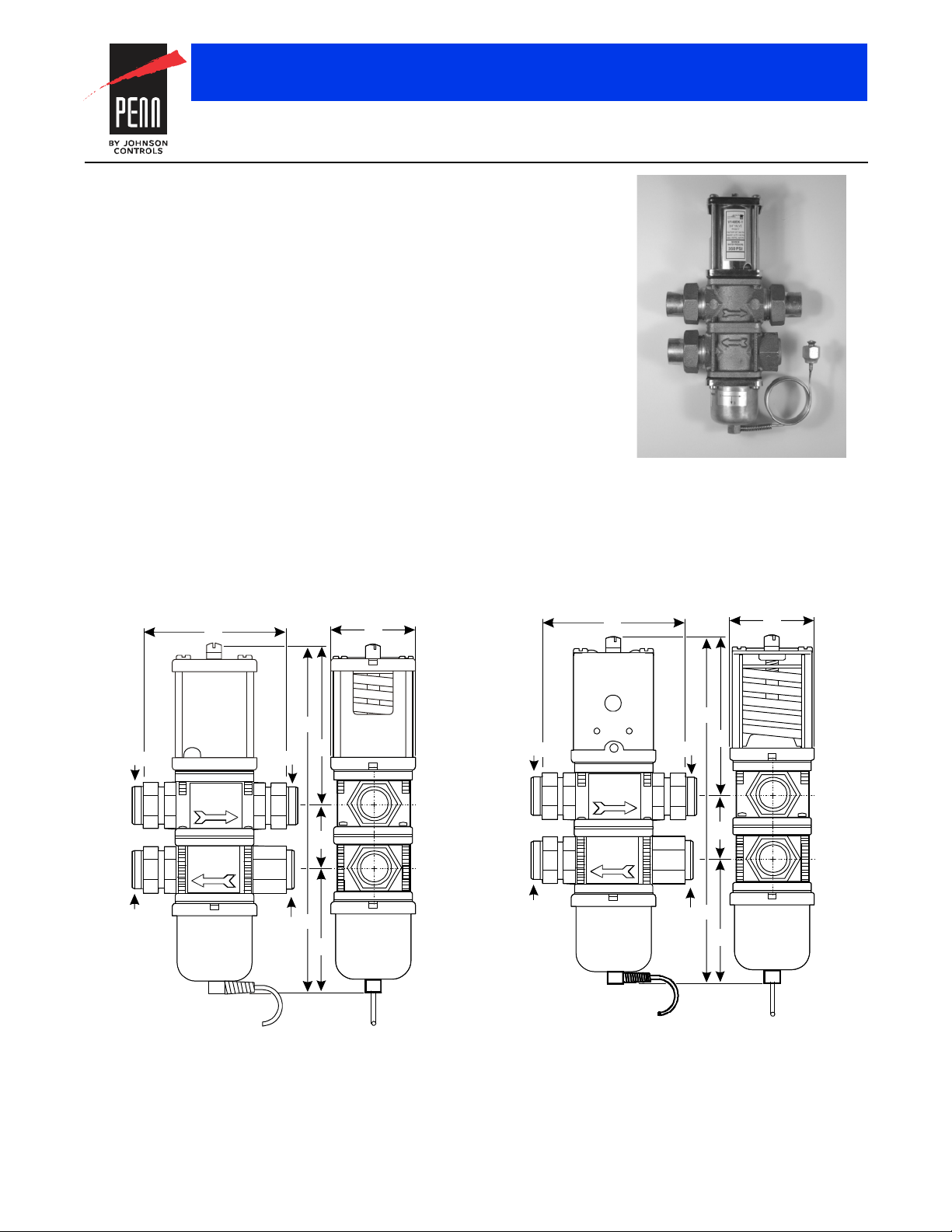
3/4 in. V148EK Valve
1 in. V148AL Valve
Pressure connec tion and capillary
as specified
A
Port 1
Port 3
Port 2
FIG:V148AL_ 100_dim
V148 Series Three-Way Pressure-Actuated Water-Regulating Valves
Description
The V148 Series Three-Way
Pressure-Actuated Water-Regulating Valves
regulate water flow to control refrigerant head
pressure in systems with single or multiple
water-cooled condensers. The V148 valves
are designed for applications with system
water pressures of up to 350 psi (24.1 bar),
such as high-rise buildings.
V148EK and V148AL valves have an
adjustable opening point in a refrigerant
pressure range of 145 to 190 psi (10.0 to
13.1 bar). V148EK and V148AL valves are
available in 3/4 in. and 1 in. sizes. Use these
valves with standard, non-corrosive
refrigerants.
V148GK1 and V148GL1 valves have an
adjustable opening point in a refrigerant
pressure range of 200 to 400 psi (13.8 to
27.6 bar). The V148GK1 and V148GL1
Valves are available in 3/4 in. and 1 in. sizes
for use with standard, non-corrosive,
high-pressure refrigerants.
Refer to the V148 Series 3-Way
Pressure-Actuated Water-Regulating Valves
Product Bulletin (LIT-121712) for important
product application information.
Valves and Valve Accessories
Features
• no close-fitting or sliding parts in water
passages
• high water pressure design
• pressure-balanced design
• corrosion-resistant material for internal
parts
• accessible range spring
• take-apart construction
Applications
Each application is unique and requires
specific engineering data to properly size and
design a system to fulfill the appropriate
requirements. Typically, a valve is replaced
with another valve of the same size in a
properly sized and engineered system.
Code No. LIT-1900164
B
C
D
E
Pressure connect io n and capillar y
Plugged
F
C
D
E
Plugged
F
B
The performance specifications are nomina l and con form to accep table ind ustry stand ards. For applicati ons at con ditions be yond these specification s, consult th
Johnson Controls, Inc. shall not be liable for damages resulting from misapplication or misuse of its products. © 2015 Johnson Controls, Inc.
R-166
Page 2
Flow =
(Temp. - Temp. )
Outlet Inlet
Flow Required
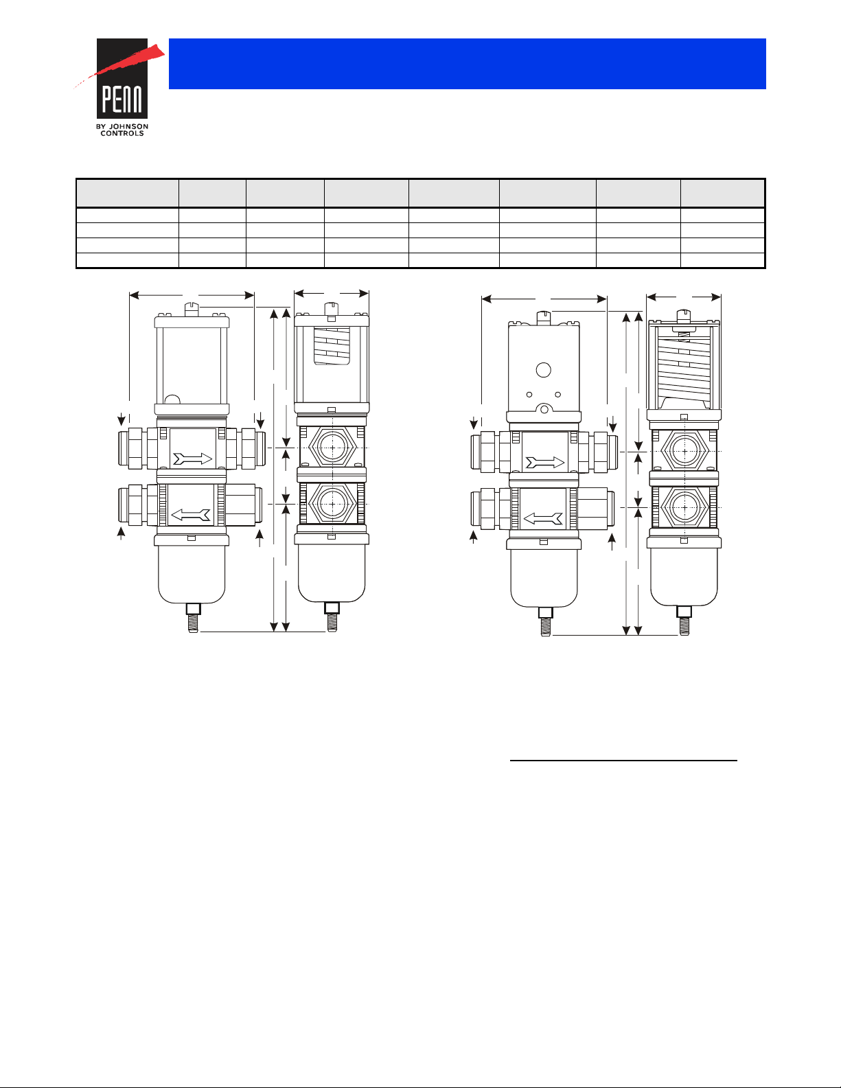
1 in. High Refrigerant Pressure V148GL1 Valves
A
Port 1
Port 3
Port 2
FIG:V148GL1_100_d im
A
Port 1
Port 3
Port 2
FIG:V148GK1_075_d im
3/4 in. High Refrigerant Pressure V148GK1 Valves
Valves and Valve Accessories
V148 Series Three-Way Pressure-Actuated Water-Regulating Valves
(Continued)
Valve Dimensions, Inches (Millimeters)
Model Nominal
Valve Size
V148EK-1C 3/4 in. 3-3/8 (86) 2-3/16 (56) 9 (229) 4-3/16 (106) 1-3/4 (44) 3 (76)
V148GK1-001C 3/4 in. 3-3/8 (86) 2-3/16 (56) 9-13/16 (249) 4-3/16 (106) 1-3/4 (44) 3-13/16 (97)
V148AL-1C 1 in. 4-3/4 (121) 2-3/4 (71) 12 (305) 5-15/16 (151) 2 (51) 4 (102)
V148GL1-001C 1 in. 4-3/4 (121) 2-3/4 (71) 12-1/2 (318) 5-15/16 (151) 2 (51) 4-1/2 (115)
A B C D E F
Plugged
B
C
D
E
F
C
D
E
Plugged
F
B
Selection
To make a rough field estimate of the size of valve for an application,
find the valve size by locating a point on a flow chart that satisfies these
requirements:
• water flow required by the condenser (Flow)
• refrigerant head pressure rise (P
• available water pressure (P
Follow these steps, and use the information obtained to locate a point
on one of the flowcharts that satisfies all three steps.
1. Take the water flow required by the condenser (Flow) from
information provided by the manufacturer of the condensing unit. If
the manufacturer’s information is unavailable, use the following
information to make a rough approximation of maximum water flow
in gallons per minute (gpm) (cubic meters per hour [m
• System Capacity (Tons of Refrigeration)
• Outlet Water Temperature (Temp.
• Inlet Water Temperature (Temp.
The performance specifications are no minal and co nform t o acceptab le ind ustry standar ds. For appl ications at condition s beyond these specifica tions, consult th
Johnson Controls, Inc. shall not be liable for damages resulting from misapplication or misuse of its products. © 2015 Johnson Controls, Inc.
AVAIL
RISE
)
Inlet
)
Outlet
)
Calculate the flow using the following formula:
Tons of Refrigeration x 30
FIG:flw_eqn
Note: If the outlet temperature is unknown, assume it to be 10F
(5.6C) above the inlet temperature.
2. Determine refrigerant head pressure rise above the valve opening
point (P
3
/hr]):
a. The Valve Closing Pressure (P
refrigerant pressure at the highest ambient temperature the
refrigeration equipment experiences in the Off cycle. Use a
)
Pressure-Temperature Chart for the refrigerant selected to find
this pressure.
b. To approximate the Valve Opening Pressure (P
about 7 psi (0.5 bar) for EK and AL models or 10 psi (0.7 bar) for
GK1 and GL1 models to the Valve Closing Pressure.
R-167
) using the following steps:
RISE
) is equal to the
CLOSE
OPEN
), add
Page 3

Valve Opening Pressure, EK and AL Models (Top) or
GK1 and GL1 Models (Bottom)
OPEN CLOSE
OPEN CLOSE
Refrigerant Head Pressure Rise
FIG
P = P - P
Available Water Pressure
Cooling Tower
P
1
P
2
P
Loss 2
3-Way
Valve
P
IN
COND
P
P
1P2
=
-
P
P
P
=
+
+ ...
Balan c ing Valve
FIG:3w y_prss_d
3/4 in. V148EK Valve
30
25
20
15
10
5
0
10 15 20 25 30 35
7
(gpm)
Pressure Drop Through Valve (psi)
FIG:V148EK_chrt
1 in. V148AL Valve
55
50
45
40
35
30
25
20
15
10
5
10 15
20
7
(gpm)
0
Pressure Drop Thr ough Valve ( psi )
FIG:V148 AL_chrt
Valves and Valve Accessories
V148 Series Three-Way Pressure-Actuated Water-Regulating Valves
(Continued)
P = P +7 psi (0.5 bar)
P = P +10 psi (0.7 bar)
c. From the Pressure-Temperature Chart for the refrigerant
selected, read the Refrigerant Condensing Pressure (P
(operating head pressure) corresponding to the selected
condensing temperature.
d. Subtract the Valve Opening Pressure from the Refrigerant
Condensing Pressure. This gives the head pressure rise.
RISE COND OPEN
3. Determine the available water pressure to the valve (P
the following steps. This is the actual water pressure available to
force water through the valve.
a. Determine the minimum inlet pressure (P
pressure from city water mains, pumps, or other sources.
b. Pressure drop through condenser (P
water pressure between the condenser inlet and the condenser
COND
outlet. Obtain this information from the condenser manufacturer.
c. Estimate or calculate the pressure drop through all associated
piping (P
d. Subtract the P
LOSS
).
COND
and P
from PIN. The result is P
LOSS
:eqn_h d_prssr_r s
AVAIL
). This is the water
IN
) is the difference in
rp
FIG:V14 x_eqn_opn_pr ssr
COND
) using
AVAIL
Use these equations to convert between U.S. and S.I. units.
3
•1 dm
• 1 bar = 100 kPa = 0.1 MPa 1.02 kg/cm
/s = 3.6 m3/h = 15.9 U.S. gal. /min. = 13.2 U.K. gal. /min.
2
= 0.987 atm 14.5 psi
Flow
)
40 45 50 55 60
Refrigerant Head Pressure Rise (psi)
Flow
.
30
20
15
10
30
20
15
Condenser
4. Select the proper valve size from the flowcharts by locating a point
on a chart that satisfies the flow, the head pressure rise above
opening point, and the pressure drop across the valve.
The performance specifications are no minal and co nform t o acceptab le ind ustry standar ds. For appl ications at condition s beyond these specifica tions, consult th
Johnson Controls, Inc. shall not be liable for damages resulting from misapplication or misuse of its products. © 2015 Johnson Controls, Inc.
P= P- (P+ P)
AVAIL IN COND LOSS
LOSS
10
Pump
P
Loss 1
Bypass Line
Loss 1
Loss 2
R-168
25 30 35 40 45 50 55 60
Refrigerant Head Pressure Rise (psi)
Page 4

High Refrigerant Pressure 3/4 in. V148GK1 Valve
45
40
35
30
25
20
15
10
5
0 0
2
4
6
8
3
10
20
30 40
50 60 70 80 90 100
Refrigerant Head Pressure Rise (psig)
0.7
1.7 2.7 3.7 4.7 5.7 6.7
Flow
(GPM)
psi (bar)
FIG:V148GK1
High Refrigerant Pressure 1 in. V148GL1 Valve
1.3 2.3 3.3 4.3
0
10
20
30
40
50
60
70
Flow
GPM
10 20 30 40 50 60 70 80 90 100 110
3
FIG:V148GL_ chrt
Flow
3
16.2
14.2
12.2
10.2
8.2
6.2
4.2
2.2
0.2
60 (4.1)
Valves and Valve Accessories
V148 Series Three-Way Pressure-Actuated Water-Regulating Valves
(Continued)
Refrigerant Head Pressure Rise (bar)
Flow
(m /hr)
Pressure Drop
Through Valve
Refrigerant Head Pressure Rise (bar)
5.3 6.3 7.3
60 (4.1)
50 (3.4)
40 (2.8)
30 (2.1)
25 (1.7)
20 (1.4)
10 (0.7)
5 (0.3)
2 (0.1)
10
Pressure Drop Thr ough Valv e psig (m / hr )
Refrigerant Head Pressure Rise (psig)
The performance specifications are no minal and co nform t o acceptab le ind ustry standar ds. For appl ications at condition s beyond these specifica tions, consult th
Johnson Controls, Inc. shall not be liable for damages resulting from misapplication or misuse of its products. © 2015 Johnson Controls, Inc.
R-169
50 (3.4)
40 (2.8)
30 (2.1)
25 (1.7)
20 (1.4)
10 (1.0)
5 (0.3)
2 (0.1)
m/hr
Page 5

Pressure Connection Styles
Style 5
Style 46
1/4-in. SAE Extern al Flare Connector
Copper C ap i llary with
1/4-in . SAE Internal Flar e Connector
(Includes Valve Stem Depressor)
Valves and Valve Accessories
V148 Series Three-Way Pressure-Actuated Water-Regulating Valves
(Continued)
Selection Chart
Product Code Number Nominal Valve
Size
V148EK-1C 3/4 in. Union (Sweat) 46 7 (3.2)
V148GK1-001C 3/4 in. Union (Sweat) 5 7 (3.2)
V148AL-1C 1 in. Union (Sweat) 46 12 (5.4)
V148GL1-001C 1 in. Union (Sweat) 5 12 (5.4)
Repair Information
If the V148 Series Three-Way Pressure-Actuated Water-Regulating Valve fails to operate within its specifications, refer to the V148 Series
Three-Way Pressure-Actuated Water-Regulating Valves Product Bulletin (LIT-121712) for a list of repair parts available.
Inlet and Outlet Ports Pressure Connection Style Shipping Weight, lb (kg)
Technical Specifications
V148 Series 3-Way Pressure-Actuated Water-Regulating Valves
Maximum Refrigerant Pressure V148EK: 370 psig (25.5 bar)
Maximum Working Pressure V148GK1, V148GL1: 630 psig (43.4 bar)
Factory-Set Opening Point
(Port 1 to Port 2)
Opening Point Adjustment Range
(Port 1 to Port 2)
Throttling Range V148EK, V148AL: 70 psig (4.8 bar)
Media 350 psi (24.1 bar) maximum,
V148AL: 320 psig (22.1 bar)
V148EK, V148AL: 165 psig (11.4 bar)
V148GK1, V148GL1: 275 psig (19.0 bar)
V148EK, V148AL: 145 to 190 psi (10.0 to 13.1 bar)
V148GK1, V148GL1: 200 to 400 psi (13.8 to 27.6 bar)
V148GK1, V148GL1: 100 psig (6.9 bar)
-4F to 170F (-20C to 77C) glycol/water or liquids with low freezing points th at are co mp atib le wit h valve materia ls
The performance specifications are no minal and co nform t o acceptab le ind ustry standar ds. For appl ications at condition s beyond these specifica tions, consult th
Johnson Controls, Inc. shall not be liable for damages resulting from misapplication or misuse of its products. © 2015 Johnson Controls, Inc.
R-170
 Loading...