

Page 1

Instruction Manual
TopClean AS
Hygienic, Self-priming
Liquid Ring Pumps
IM-AS/02.00 GB-JPAB (0412)
Page 2

CE – Declaration of conformity
Manufacturer
Johnson Pump
Box 1436
SE- 701 14 Örebro
Sweden
We declare under our sole responsibility that the product:
Pump Series AS
CE declaration of conformity (Ann.II.A, 98/37/EEC)
to wich this declaration refers, is conform to safety requirements according
to 98/37/EEC norms and amendments
Manufacturer declaration (Ann. II.B, 98/37/EEC)
cannot be operated before the machine in which is assembled, will be declared in conformity with safety requirements according to 98/37/EEC norms
and amendments.
Örebro, Sweden, 01/03/2007
Stefan Ring
Manager Quality & Environment
Page 3

Index
1.0 Introduction ...................................................................................................... 3
2.0 Symbols ...................................................................................................... 3
3.0 Safety warnings ................................................................................................ 3
4.0 Transportation, receipt and transferring of goods ....................................... 4
4.1 Transportation .............................................................................................................. 4
4.2 Receipt .......................................................................................................................... 4
4.3 Transferring .................................................................................................................. 4
5.0 Description ...................................................................................................... 5
5.1 Sound pressure level.................................................................................................... 5
6.0 Non-permitted uses.......................................................................................... 6
7.0 Installation ...................................................................................................... 6
7.1 Suction and inflow conditions .................................................................................... 6
7.2 Piping ........................................................................................................................... 6
7.3 Electrical connection ................................................................................................... 7
8.0 Operation ...................................................................................................... 7
8.1 Preliminary operations and starting .......................................................................... 7
8.2 Operating checks ......................................................................................................... 8
8.3 Extended stop .............................................................................................................. 8
8.4 Cleaning the pump ...................................................................................................... 8
9.0 Spare parts ...................................................................................................... 8
10.0 Seals ................................................................................................. 9
11.0 Disassembly and Assembly AS-series ......................................................... 10
11.1 General instructions .................................................................................................. 10
11.2 O-rings and lip seals .............................................................................................. 10
11.3 Shutdown .............................................................................................. 10
11.4 Disassembly .............................................................................................. 11
11.4.1 Removal of pump casing and impeller – AS 40, 50, 60, 65 and 80 .......... 11
11.4.2 Removal of pump casing and impeller – AS 42 and AS 52 ...................... 11
11.4.3 Seal disassembly ............................................................................................ 12
11.4.3.1 T execution ......................................................................... 12
11.4.3.2 V execution ......................................................................... 12
11.4.3.3 Q execution......................................................................... 12
11.4.4 Bearing removal ............................................................................................ 13
11.5 Assembly .............................................................................................. 13
11.5.1 Clearances .............................................................................................. 13
11.5.2 Pump assembly AS 40, 50, 60, 65................................................................. 14
11.5.3 Seal assembly .............................................................................................. 14
IM-AS/02.00 GB (0412)
1
Page 4

11.5.3.1 T execution .......................................................................... 14
11.5.3.2 V execution .......................................................................... 14
11.5.3.3 Q execution .......................................................................... 15
11.5.4 Assembly of pump casing and impeller assembly ........................................
– AS 40, AS 50, AS 60, AS 65 and AS 80 ................................................... 15
11.5.5 Pump cover and Impeller assembly – AS 42 and AS 52 ........................... 16
12.0 Spare parts lists and sectional drawings ...................................................... 17
12.1 Spare part list AS 40, 50, 60-65, 80 .......................................................................... 17
12.2 AS 40 – Execution T, Q, V........................................................................................ 18
12.3 AS 50 – Execution T, Q, V........................................................................................ 19
12.4 AS 60-65 – Execution T, Q, V .................................................................................. 20
12.5 AS 80 – Execution T, Q, V........................................................................................ 21
12.6 Spare part list AS 42, 52 ............................................................................................ 22
12.7 AS 42 – Execution T, Q, V........................................................................................ 23
12.8 AS 52 – Execution T, Q, V........................................................................................ 24
13.0 Dimensions and weights .............................................................................. 25
13.1 AS 40-50-60-65-80 with shroud 1450 rpm ............................................................... 25
13.2 AS 40-50-60-65-80 without shroud 1450 rpm ......................................................... 25
13.3 AS 42-52 with shroud 1450 rpm ............................................................................... 26
13.4 AS 42-52 with shroud 1450 rpm ............................................................................... 26
14.0 Trouble shooting chart .............................................................................. 27
15.0 Disposal of the pump .............................................................................. 28
2
IM-AS/02.00 GB (0412)
Page 5
1.0 Introduction
• Read the instructions carefully and keep them for future consultation.
• Johnson Pump reserves the right to make any changes to the documentation it
deems necessary without being obliged to update publications that have already
been issued.
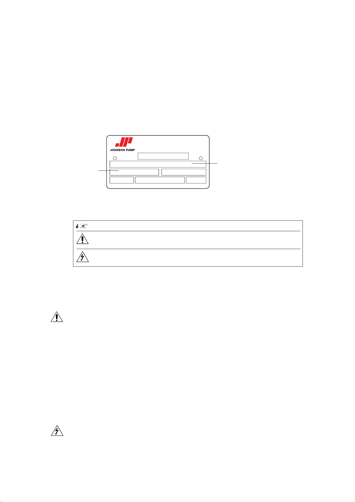
•When requesting information, spare parts or assistance, always specify the pump
type and serial number in order to ensure fast and efficient service: the complete
code is given on the plate and in the purchase documents.
Serial No.
No.
kW
Nastagatan 19, Örebro, Sweden · Tel +46 (0)19 21 83 00
Name plate
2.0 Symbols
TopClean
Item
r.p.m.
Volt
Pump type
Hz
Warning: Pay great attention to the text parts indicated by this symbol.
Danger: The non-observance of instructions can cause serious damage
to persons and/or objects.
Danger:Only skilled personnel is allowed to carry out operations
concerning the electric parts.
3.0 Safety warnings
When the pump is working the following occurs:
• Electric parts are in tension.
•Mechanical parts are moving.
• Pump body, pipelines and articulations are under internal pressure. Therefore do not
remove any protection or locking, do not loosen screws or clampings, as this can
cause serious damages to persons or objects. The clamp joining the pump casing and
the cover must be well tightened and it should not be easily unscrewed by hand. The
tightening of the clamp must be carried out by means of a key and not by hand.
• Non-observance of inspection and maintenance can cause damages to persons and
objects, especially when dangerous or toxic liquids are pumped.
•When pumping liquids at a temperature over 60°C, adequate protection and
warning signals are required.
•When you buy a pump with bare shaft, motor coupling operations have to be
•Operations on the electric parts have to be carried out by skilled personnel,
• Installation must ensure adequate ventilation, in order to cool the engine, as well as
IM-AS/02.00 GB (0412)
carried out according to technical directions and law, providing adequate
rotections for joints, gear belts, etc.
according to technical directions and law, on authorisation of the responsible
installer.
enough space for maintenance operations.
3
Page 6
Before carrying out any operation which requires to disassembly of the pump
(inspection, cleaning, seal replacement, etc.), the following preliminary operations have
to be carried out:
• Switch off engine tension and disinsert electric connection.
• Close valves on suction and outlet pipelines, in order to avoid the risk of inundation.
•Use adequate protection for hands and face, if the pump contains liquids which are
hazardous to health (for example acids, solvents, etc.).
• Consider whether the liquid which flows out of the pump when disassembling is
dangerous and arrange for adequate safety measures.
4.0 Transportation, receipt and transferring of goods
4.1 Transportation
The packings of all AS pumps are defined when making the order. Unless prior arrangements
are given, goods will be packed only for transit conditions and not for long-term storage; in case
it should be necessary to store the pumps outside, you are requested to cover the pumps
appropriately in order to protect the electrical parts (motor) from rain, dust, humidity etc.
4.2 Receipt
Upon receipt of goods the integrity of the packaging must be verified in order to identify
possible damages to the content during transfer, and to claim immediately from the carrier.
Should any damage be ascertained, the following procedure must be observed:
• Collect the goods with receipt.
• Take the necessary pictures showing the damages.
• Notify the carrier of the suffered damages, by registered airmail – including the
pictures taken.
4.3 Transferring
Carry the packed pumps as close as possible to the place of installation by means of appropriate
lifting devices and unpack them. During this operation take care, as unsteady parts could fall
down.
The material used for packing (wood, paper, cellophane, etc.) should be properly disposed of,
according to the corresponding rules in force in receiver’ s country.
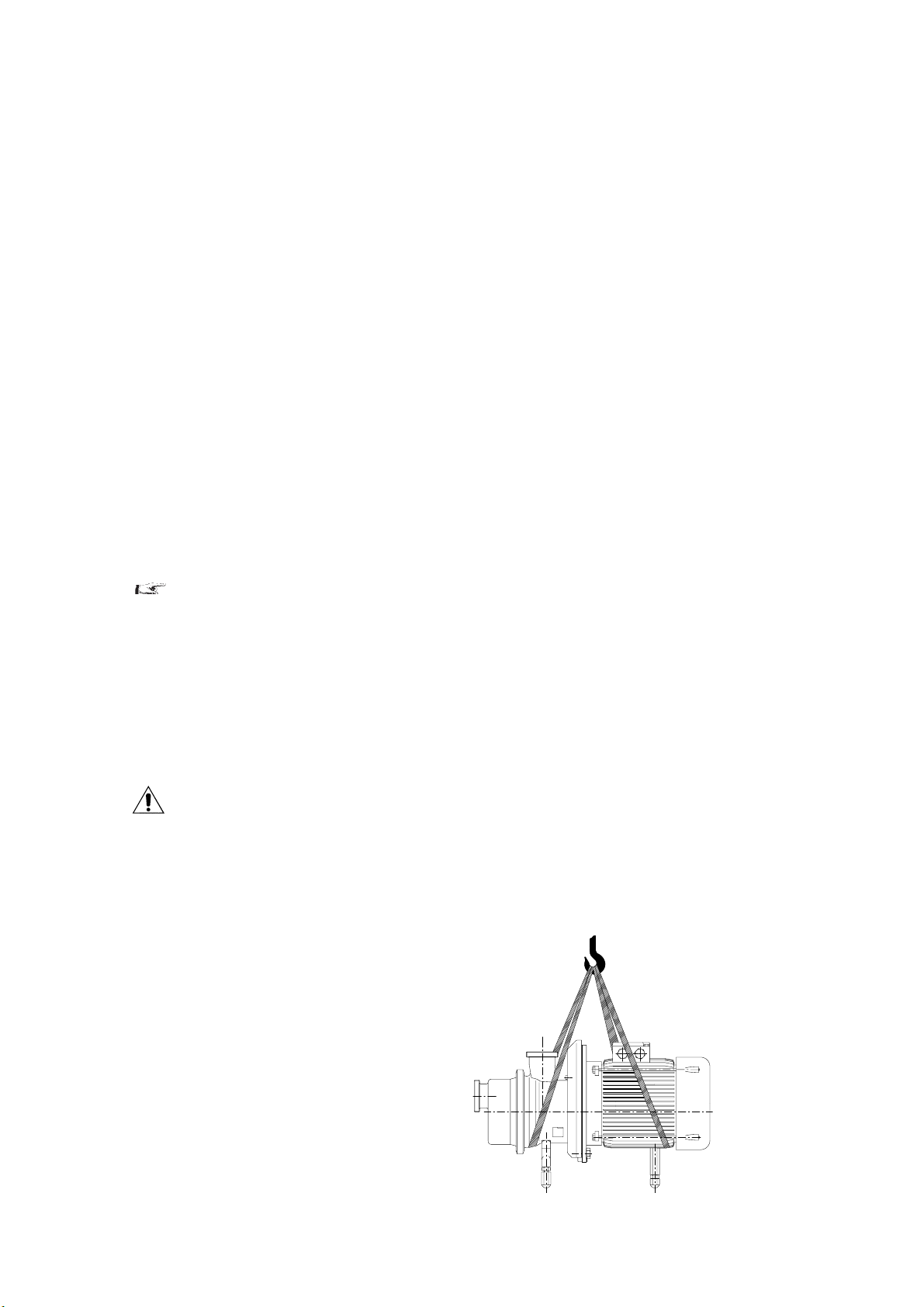
After unpacking the pump, use special lifting belts and move the pump-motor-set to the place
of installation; never use the eyebolts on the motor to move the pump, as the eyebolts are for
moving the motor only.
In versions complete with shroud,
take the shroud off before moving the
pump-motor-set, in order to avoid
damages.
4
IM-AS/02.00 GB (0412)
Page 7

5.0 Description
The pumps of series AS are centrifugal side channel self-priming with star-shaped impeller; the
ports are located on the longitudinal axe with the suction located on the front of the pump
cover. All models have threaded connections for fittings according to DIN 11851 standard
(unless otherwise requested). The pump front cover is easy to open to improve cleaning and
inspection operations; all models are fitted with mechanical seals and the materials used for the
components of mechanical seal are chosen according to the liquid to be pumped.
Designed in close-coupled version, fitted with indepandant standard electric motors B5 shape,
IP 55 protection (unless otherwise requested).
These pumps are designed for applications where the liquid to be pumped :
• is not subject to pollution of any kind,
• is at a temperature between -30°C and +140°C,
•must under no circumstances come into contact with the outside environment,
• is chemically aggressive.
5.1 Sound pressure level
The sound pressure level of self-priming pumps is the following (see table):
The measurement has been made by means of a phon-meter placed at 1 m distance from the pump
and at a height of 1.6 m from the ground.
Preliminary condition is that the pump is fixed correctly; the above mentioned values do not take
into account external noise sources (e.g. valves, abrupt hydraulic deflections).
Pump type dB(A)
AS 40 < 80
AS 42 81-85
AS 50 81-85
AS 52 86-90
AS 60 86-90
AS 65 86-90
AS 80 86-90
IM-AS/02.00 GB (0412)
5
Page 8
6.0 Non-permitted uses
Do not use the pump with a suction pressure greater than the specified value (0.5 times
the discharge head generated by the pump).
The pump must always be used in an environment appropriate to the level of protection
of the motor. Always check this on the motor plate before installation.
The pump may not be used in environments which require a higher level of protection or
a higher specification motor or electrical parts.
Components complying with the safety standards for the environment in question must
be used.
7.0 Installation
7.1 Suction and inflow conditions
(NPSH = Net Positive Suction Head)
NPSH of system (available NPSH)
In order to ensure that pump operation is free from cavitation, it is essential to observe
the maximum permitted suction lift ha geo max or the minimum allowable head hc geo
min. NPSH of pump (required NPSH)
The centrifugal pumps can operate correctly only if vapour has not formed inside. For
this reason the static head at the reference point for the NPSH is the centre of the
impeller, that is the point of intersection of the pump shaft axis with the vertical plane
that passes through the external points of the blade inlet corners.
NPSHnec. is the value required by the pump, expressed in metres, obtained from the
performance curve. In practice 0.5 m should be added to this value as a safety margin.
7.2 Piping
In order to prevent the creation of harmful stresses, the suction and discharge pipes must
be connected to the pump ports without the use of force. These pipes must also be
supported independently avoiding causing stresses on the pump. The internal diameter
must be the same size as the pump connections. It must in any case not be smaller to
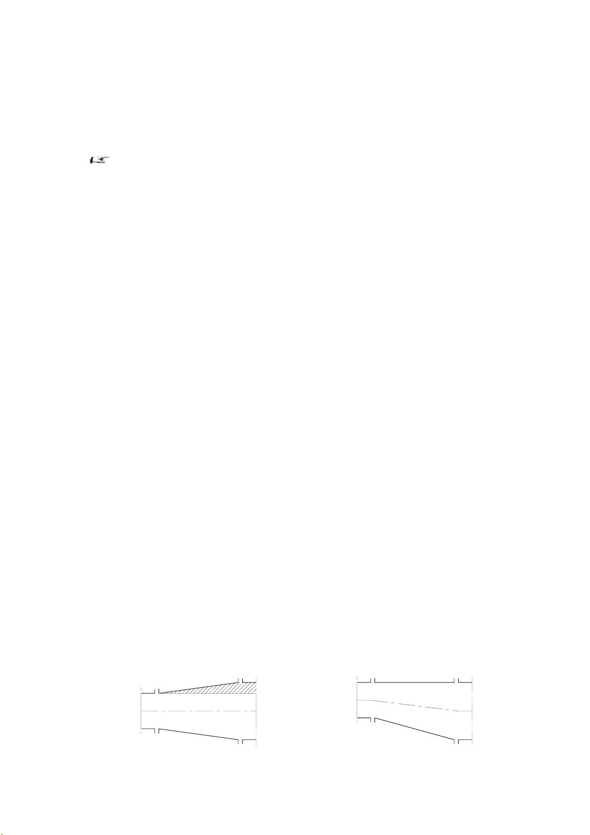
avoid head loss and/or poor performances. Always use elbows with large radius. If the
pipe diameter changes along the line, use reduction cones, choosing the ones that are
most suitable for avoiding the formation of air pockets (Fig. 1).
The suction pipe must be as short as possible and rise as it moves towards the pump if it
is sucking from a tank, if on the other hand the pump is below the level of the liquid, the
pipe should descend slightly. If the pump is used for transporting hot liquids, fit expansion joints to compensate any expansion of the piping. The maximum velocity of the
liquid in the suction pipe must not be greater than 3 m/s. Velocities between 1 and 2 m/s
are recommended.
The suction pipe must be designed in such a way as to prevent air from entering the
pump. For this reason, when sucking from a tank located at a lower level, the pipe must
reach below the free surface of the liquid. Avoid creating obstacles which could increase
suction losses disrupting smooth fluid flow. Make sure that there are no restrictions,
NO
YES
Fig. 1
6
IM-AS/02.00 GB (0412)
Page 9
7.3 Electrical connection
Make the electrical connection only after the hydraulic connection has been completed; set up
the motor control system in conformity with the technical standards and regulations in force
(EN 60204-1): in particular a manual electric power switch must be installed with adequate
current switching capacity; devices for overcurrent and overload protection (e.g. fuses,
automatic switches, etc.) must also be fitted, plus, if necessary, a device to prevent accidental
restarting.
Check that the main frequency and voltage and the available power are suitable for the motor
installed. All the material used for the electrical connection (cables, cable clamps, switches and
shielding) must have a suitable level of protection for the environment in which it is installed.
Be sure to use cables of sufficient cross-section for the current shown on the motor plate so as
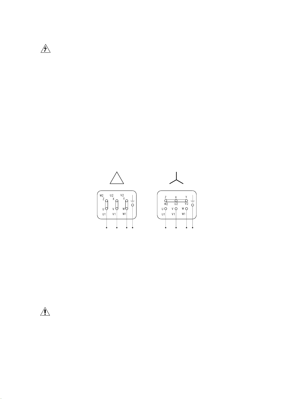
to prevent them from overheating. Before doing anything else, make the motor’s earth
connection, using the terminal on the motor and a cable of sufficient cross-section. The cables
may be connected to the terminal board using either a delta or star arrangement. Follow the
data given on the motor plate for the main voltage, as shown in the diagram in fig 2; ensure that
the terminals are clean and tight and not under stress.
When starting, the motor’s current absorption increases briefly to 5-6 times the nominal value.
If the mains supply is unable to sustain this increase in absorption, use a star-delta starter or
other kind of device (e.g. an autotransformer).
Johnson Pump will accept no responsibility for damage to property and/or injury to persons
caused by failure to comply with technical standards and regulations in force.
Lower
voltage
Fig 2
8.0 Operation
8.1 Preliminary operations and starting
When first starting, fill the pump with liquid so as to create the pressure drop required for
suction. When starting subsequently the quantity of liquid that remains in the pump will be
sufficient to ensure self-priming even if the pipe is empty. Make sure that the pump does not
become completely empty in the event of installation under a vacuum or to a siphon. If
necessary, fit a check valve.
• Check that the pump turns freely under hand pressure.
• Check that the clamp joining the pump casing and the cover is well tightened and that
it cannot be easily unscrewed by hand. The tightening of the clamp must be carried out
by means of a key and not by hand.
Higher
voltage
• Check that the pump turns in the market direction.
• Check that any gate valves installed on the suction and discharge pipelines are open.
• Start the pump and check the turns direction; before restarting it is extremely important to
IM-AS/02.00 GB (0412)
7
Page 10
8.2 Operating checks
• If the pump does not generate the required discharge head rapidly, facilitate
priming by stopping the pump and adding liquid.
• Check that the absorption of the motor does not exceed the value specified on the
plate.
• The pump must always work smoothly and without vibrations.
•Do not operate without liquid and in any case avoid prolonged operation with the
discharge gate valve closed.
• With series AS pumps never close discharge side completely.
•Mechanical seal: check that there is no leakage along the shaft.
8.3 Extended stop
When stopping the pump for a longer time, empty the pump completely and wash it
accurately in order to avoid the formation of scales and/or encrustations. When starting
the pump again, please follow the above mentioned instructions.
8.4 Cleaning the pump
The pump does not require any special washing procedures. The washing cycles
normally used for the plant in which it is installed are quite satisfactory. When using the
pump for liquids that tend to harden or crystallize, always make sure it is washed before
periods when the machine is to be taken out of operation. This will ensure durability of
the seal and of the pump itself.
It is the user’s responsibility to ensure that the washing liquids are compatible with the
process liquid and the pump.
9.0 Spare parts
Denomination Number of pumps
Mechanical seal 1 2 3 4 4
Pump bearing 1 1 1 2 2
O-ring seal 2 3 5 6 7
O-ring seal nut 2 3 5 6 7
Recommended spare part for two years of operation according to the
number of pumps installed – vdma standard
Johnson Pump declines all responsibility for damage or injury resulting from the use of
non-original spare parts
(Including reserve)
12345
8
IM-AS/02.00 GB (0412)
Page 11

10.0 Seals
All centrifugal pumps of the AS series are fitted with unified mechanical seals according
to DIN 24960 - ISO 3069 standards, in order to grant the interchangeability (subject to
verification of axial space). The type of mechanical seal and material are chosen
according to the liquid to be pumped.
Mechanical seal types conforming to DIN 24960
•T execution: Standard – Internal single mechanical seal
•V execution: External single mechanical seal with external
•Q execution: Compact double mechanical seal back-to-back,
Warning: before using the pump for any liquids other than those specified when
selecting and ordering, ensure that mechanical seals and gaskets are suitable for the new
product.
flushing/quench.
high pressure flush
IM-AS/02.00 GB (0412)
9
Page 12

11.0 Disassembly and Assembly AS-series
11.1 General instructions
Assembly and disassembly may be preformed by qualified personnel only. Always wear
appropriate safety clothing. Make sure that personnel are instructed and educated.
Insufficient or wrong assembly and disassembly can lead to the pump malfunction.
Johnson Pump is not liable for accidents and/or damage caused by non-compliance with
the guidelines.
Always work in a clean surrounding. Keep all highly sensitive parts such as seals, Orings, bearings, etc. in their original packing as long as possible.
Use a clean work surface.
Check that the parts to be used have not been damaged during transport.
Never work on the pump in operation. In case of a disassembled pump, avoid any
contact with the impeller when turning the shaft manually.
Do not forget that the pump can be started even when the pump casing has been removed for e.g. cleaning. Never run the pump without the pump casing. Follow the
instructions for shutdown before performing any maintenance or service.
After disassembly carefully clean the parts and check them for damage, especially the
mounting surfaces, and replace all damaged parts.
All parts fitted together at the disassembly must stay together when reinstalled,
especially the impeller, shaft, shim and back plate.
11.2 O-rings and lip seals
When working with lip seals or O-rings, take care not to damage them as they pass over
sharp edges of splines, threads, etc. Be sure that the O-rings are not twisted in the groove
when installing.
All O-rings and sealing lips should be lubricated with a suitable lubricant before fitting,
e.g. soap and water or silicone spray.
For O-rings made of PTFE, it is advised to heat them up in hot water before placement.
A warmed up O-ring becomes softer, thus easier to install. Be aware of that PTFE has
no thermal memory.
11.3 Shutdown
Before starting the maintenance or inspection, follow the next steps to shut down the pump.
1. Stop the pump. To prevent the motor from starting while you are working on the
pump follow the procedure below:
• Turn off the pump at the electrical cabinet.
• Set the pump circuit breaker to off.
• Switch off and lock the operating switch.
• Remove the fuse.
• Sign the electrical cabinet “danger”.
10
2. Remove, if necessary, the protection around the shaft coupling when the pump
has stopped completely.
3. Let the pump cool down to ambient temperature.
IM-AS/02.00 GB (0412)
Page 13

4. Isolate and depressurize flushing/quench system.
5. Close the inlet and discharge valves.
6. Drain and purge the pump casing and pipe work.
7. Clean the pump externally before disassembly.
11.4 Disassembly
11.4.1 Removal of pump casing and impeller – AS 40, 50, 60, 65 and 80
See sectional drawings AS40 page 18, AS 50 page 19
1. Remove the mechanical seal flushing pipes 71 on V and Q executions.
2. Remove the shroud (44) with screws (46) (if shroud is assembled).
3. Loosen screws (28) to remove the motor (50).
4. Gently pull the motor (50) away from the bearing housing (5).
5. Motor sizes up to IEC 112. If necessary remove the adjustable foot frame by
loosening the two nuts (30) and the screws (29).
6. Motor sizes larger than IEC 112. If necessary remove the adjustable foot
frame by loosening the screws (29) to remove the front foot (20), and the rear
foots (23).
7. Loosen and remove the casing clamp (9).
8. Remove the casing cover (2).
9. Unscrew the impeller nut (10) anti-clockwise and slide off the impeller (3).
10. Remove the impeller key (11).
11. Remove the clearance shims (19).
11.4.2 Removal of pump casing and impeller – AS 42 and AS 52
See sectional drawings AS 42 page 23 and AS 52 page 24
1. Remove the mechanical seal flushing pipes 71 on V and Q executions.
2. Remove the shroud (44) with screws (46) (if shroud is assembled).
3. Loosen the screws (28) to remove the motor (50).
4. Gently pull the motor (50) away from the bearing housing (5).
5. Motor sizes up to IEC 112. If necessary remove the adjustable foot frame by
loosening the two nuts (30) and the socket head screw (29).
6. Motor sizes larger than IEC 112. If necessary remove the adjustable foot
frame by loosening the socket head screw (29) to remove front foot (20), and
the rear foots (23).
7. Loosen and remove the rag bolt (38).
8. Remove the casing cover (2).
9. Remove the first impeller (3) as well as the impeller key (11).
10. Remove the inter-discharge casing (35) and the intersuction casing (34).
11. Remove the second impeller (3) as well as the impeller key (11).
IM-AS/02.00 GB (0412)
11
Page 14

11.4.3 Seal disassembly
11.4.3.1 T execution
1. AS 42 and AS 52 only. Push back the ring retainer (31) to remove the circlip (32)
from the shaft (4).
2. Remove the rotating seal half by turning the spring clockwise and at the same
time pull the spring and the seal over the shaft end. If necessary use a pair of pliers.
3. Loosen the screws (26).
4. Slowly remove the pump casing (1) from the bearing housing (5).
5. Remove the stationary seal part from its seat in the pump casing (1).
Pull off the thrower (14).
11.4.3.2 V execution
1. AS 42 and AS 52 only. Push back the ring retainer (31) to remove the circlip (32)
from the shaft (4).
2. Remove the rotating seal half by turning the spring clockwise and at the same
time pull the spring and the seal over the shaft end. If necessary use a pair of pliers.
3. Loosen the screws (26).
4. Slowly remove the pump casing (1) from the bearing housing (5).
5. Loosen the stud bolt (68)
6. Gently pull off the mechanical seal cover (65) from the pump casing (1).
7. Remove the radial seal (66) from the mechanical seal cover (65 )
11.4.3.3 Q execution
1. AS 40, 42, 60-65, 80. Loosen and remove the stud bolts (68)
AS 50, 52 on the stud bolts (62).
1. Separate the mechanical seal cover (60) from the pump casing (1) by pushing it
backwards.
2. Loosen the screws (26).
3. Pull the pump casing (1) gently from the bearing housing (5).
4. Remove the primary stationary seal from the rear of the pump casing (1).
5. Loosen the grub screws on the rotating seal
6. Slide off the rotating seals along the shaft (4).
7. Remove the mechanical seal cover (60) by gently pulling it over the shaft (4).
8. Push out the secondary stationary seal from the mechanical seal cover (60).
9. Remove the O-ring (61).
10. Pull off the thrower (14).
12
IM-AS/02.00 GB (0412)
Page 15

11.4.4 Bearing removal
1. Remove shroud adapter (43) (if assembled) by loosening the screws (45).
2. Unscrew the screws (27).
3. Remove the bearing cover (8).
4. Press out the shaft and bearing assembly from the bearing housing (5).
5. Unscrew the ring nut (17).
Press out the shaft (4) from the bearing (7).
11.5 Assembly
Remark: It is recommended to pre-assemble the pump without the seal. Shim the pump
according to the clearance table to obtain the correct impeller clearance, and thereafter
assemble the pump with seal.
Exception: AS 42 and AS 52 (two stage pumps) which have floating impellers (shim free).
11.5.1 Clearances
Defined clearances for AS – range to be shimmed
•A= Behind impeller, Clearance between Impeller and Pump casing
• B= Front of impeller, Clearance between Impeller and Cover
• C= Clearance between, Pump Casing and Cover
To remember:
C clearance is machined, B will be given depending on the shims put under A, Behind
impeller, should be correct
If problems occur concentrate on the A clearance it is the most important, if there will
be a deviation make sure that it will be at B clearance
If it is other problems please contact Johnson pump or dealer for advice.
Pump clearances defined and shimmed
AS
pumps A B C
AS 40 0.15 15
AS 50 0.15 0.15 2.85
AS60-65 0.2 0.2 2.80
AS 80 0.3 0.3 4.20
C
B
IM-AS/02.00 GB (0412)
A
13
Page 16

11.5.2 Pump assembly AS 40, 50, 60, 65
Before assembly read chapters 11.1 General Instructions and 11.2 O-rings and lip seals.
N.B. Make sure that all surfaces are clean and without damage. If necessary polish using
(600 degrees) emery cloth, lubricate all O-rings and contact surfaces with soap and water
or silicone spray.
1. Check the shaft condition – no tracks of wear etc. Clean it carefully.
2. Press the bearings (7) on to the shaft (4).
3. Assemble the ring nut (17) and tighten it.
4. Press the shaft (4) and bearing assembly into the bearing housing (5).
5. Assemble the bearing cover (8). Tighten it with the screws (27).
6. Push the thrower (14) on the shaft (4).
7. Assemble the shroud adapter (43) (if shroud should be assembled) with
screws (46).
11.5.3 Seal assembly
11.5.3.1 T execution
1. Insert the stationary seal part into the pump casing (1) by gently pushing it.
2. Assemble the pump casing (1) together with the bearing housing (5). Be careful
with the seal when sliding it over the shaft. Tighten the pump casing with the screws
(26).
3. Fit the rotating part of the seal on the shaft (4).
4. N.B. Assemble the mechanical seal carefully to avoid damages on the seal faces and
O-rings..
5. AS 42 and AS 52 only. Fit the ring retainer (31) on the shaft (4). Compress the spring
on the rotating seal with the ring retainer and lock it with the circlip (32).
11.5.3.2 V execution
1. Press the radial seal (66) into the mechanical seal cover (65).
2. Fasten the stud bolt (68) on the pump casing (1).
3. Slide the mechanical seal cover (65) on the stud bolts (68) and tighten
them.
4. Insert the stationary seal part into the pump casing (1) by gently pushing it.
5. Assemble the pump casing (1) together with the bearing housing (5). Be
careful not to damage the radial seal (66). Tighten the pump casing with screws
(26).
6. Fit the rotating part of the seal on the shaft (4).
N.B. Assemble the mechanical seal carefully to avoid damages on the seal
faces and O-rings.
7. AS 42 and AS 52 only. Fit the ring retainer (31) on the shaft (4). Compress the spring
on the rotating seal with the ring retainer and lock it with the circlip (32).
14
IM-AS/02.00 GB (0412)
Page 17

11.5.3.3 Q execution
1. Position the O-ring (61) on the mechanical seal cover (60).
2. Position the secondary stationary seal in the mechanical seal cover (60) and hexhead screws (62).
3. Slide the mechanical seal cover (60) onto the shaft (4) and position it on the back
end of the shaft.
4. Gently slide the rotating seals onto the shaft (4).
5. Check the “A” length as it is essential for an
equal working load on both seal faces,
A measures as follows:
•AS 40 = 16.0mm
•AS 50 = 17.5mm
•AS 60 = 15.5mm
•AS 65 = 15.5mm
•AS 80 = 19.5 mm
6. Tighten the grub screws on the rotating seal.
7. Fit the primary stationary seal part in the
back of the pump casing (1).
8. Assemble the pump casing (1) onto the
bearing housing (5). Be careful not to damage the seal. Tighten with the screws (26).
A
9. Fit the mechanical seal cover (60) together with the pump casing (1) and lock it
with the (62).
11.5.4 Assembly of pump casing and impeller assembly – AS 40, AS 50, AS 60, AS 65 and AS 80
1. Fit the correct clearance shims (19) (adjusted from pre-fitting)
2. Fit the impeller key (11) and push on the impeller (3).
3. Fit the O-ring (16) in the impeller nut (10) and tighten the impeller (3).
4. Assemble the O-ring (13) in the pump casing (1) groove.
5. Assemble the cover casing (2) and lock it with the casing clamp (9).
6. Motors up to size IEC 112. Fit the adjustable foot frame and lock it with the nuts
(30) and the screws (29).
7. Motor sizes larger than IEC 112. Fit the adjustable foot frame and fasten the screws
(29) for the front foot (20) and the rear foots (23).
8. Assemble the motor (50) by entering the motor shaft into the pump shaft (4) and
lock it with the screws (28).
9. Slide the shroud (44) over the motor (50) and assemble it on the adapter (43) with
the screws (46)
10. ‘‘V’’ and ‘‘Q’’ executions. Assemble the mechanical seal flushing pipes (71 and 71
respectively) on the mechanical seal cover ( 65 and 60 respectively).
IM-AS/02.00 GB (0412)
15
Page 18

11.5.5 Pump cover and Impeller assembly – AS 42 and AS 52
See drawing
1. Fit the first impeller key (11) and push on the impeller (3) on the shaft (4).
2. Fit the O-ring in the pump casing (1) groove and assemble the inter-suction casing
(34).
3. Fit the O-ring (36) in the inter-suction casing (34) and assemble the inter-discharge
casing (35).
4. Fit the second impeller key (11) and push on the impeller (3) on the shaft (4)
5. Fit the O-ring (36) in the inter-discharge casing (35). Assemble the cover casing (2)
with the rag bolts (38).
6. Motors up to size IEC 112. Fit the adjustable foot frame and lock it with the nuts
(30) and the screws (29).
7. Motor sizes larger than IEC 112 or. Fit the adjustable foot frame and fasten the
screws (29) for the front foot (20) and the rear foots (23).
8. Assemble the motor (50) by entering the motor shaft into the pump
shaft (4) and lock it with the screws (28)
9. Slide the shroud (44) over the motor (50) and assemble it on the adapter (43) with
the screws (46)
10. ‘‘V’’ and ‘‘Q’’ executions. Assemble the mechanical seal flushing pipes (71 and 71
respectively) on the mechanical seal cover ( 65 and 60 respectively).
16
IM-AS/02.00 GB (0412)
Page 19

12.0 Spare parts lists and sectional drawings
12.1 Spare part list AS 40, 50, 60-65, 80
Pos Qty Description Material
11Casing, pump CF-3M / 1.4409
1 Q 1 Casing, pump Q-execution CF-3M / 1.4409
1 V 1 Casing, pump V-execution CF-3M / 1.4409
21Cover, casing CF-3M / 1.4409
31Impeller CF-3M / 1.4409
41Shaft AISI 316 L / 1.4404
4 V 1 Shaft V-execution AISI 316 L / 1.4404
51Housing, bearing Cast iron 25 + 3%Ni
61Mechanical seal 6 Q 1 Mechanical seal, Q-execution -
71Bearing Steel
81Bearing cover Aluminum 2011
91Clamp, casing AISI 304 / 1.4301
10 1 Nut, impeller AISI 316 L / 1.4404
11 1 Key, impeller AISI 316 / 1.4401
12 1 Pin AISI 304 / 1.4301
13 1 O-ring EPDM
14 1 Thrower NBR
15 1 Shaft plug NBR
16 1 O-ring EPDM
17 1 Nut, ring Galvanized iron
18 1 Grease nipple Galvanized iron
19 2 Shim AISI 316 L / 1.4404
20 1 Foot, front CF-8 / 1.4308
21 2 Foot, adjustable AISI 304 / 1.4301
23 1 Foot, rear CF-8 / 1.4308 - AISI 304 / 1.4301
25 1 Foot, adjustable AISI 304 / 1.4301
26 4 Screw, socket head AISI 304 / 1.4301
27 3 Screw, socket head AISI 304 / 1.4301
28 4 Screw, hex-head Steel
29 2 Screw, socket head AISI 304 / 1.4301
30 2 Nut AISI 304 / 1.4301
33 1 Gaco-ring NBR
40 2 Lantern guard AISI 304 / 1.4301
43 1 Shroud, adapter AISI 304 / 1.4301
44 1 Shroud AISI 304 / 1.4301
45 3 Screw, hex-hollow AISI 304 / 1.4301
46 3 Screw, flat head AISI 304 / 1.4301
50 1 Motor-electric 60 Q 1 Mechanical seal cover Q-execution AISI 304 / 1.4301
61 Q 1 O-ring Q-execution NBR
62 Q 2 Screw, hex-head Q-execution AISI 304 / 1.4301
65 V 1 Mechanical seal cover V-execution AISI 304 / 1.4301
66 V 1 Seal, radial shaft V-execution 68 Q 2 Stud bolt Q-execution AISI 304 / 1.4301
68 V 2 Stud bolt V-execution AISI 304 / 1.4301
70 V 1 O-ring V-execution NBR
71 Q 2 Mechanical seal flushing pipe Q-execution AISI 304 / 1.4301
71 V 2 Mechanical seal flushing pipe V-execution AISI 304 / 1.4301
85 V 1 Ceramic hardened bush V-execution AISI 304 / 1.4301
86 V 1 O-ring V-execution NBR
87 V 3 Dowel V-execution AISI 304 / 1.4301
IM-AS/02.00 GB (0412)
17
Page 20

12.2 AS 40 – Execution T, Q, V
Execution T
44
50 17 8 26 45 46 43 15 4 1 6 12 11 10 2
20 27 25 28 5 7 14 29 21 30 19 13 9 3 16
Execution Q
60 Q
61 Q 6 Q 1 Q
71 Q
68 Q
Execution V
66 V
71 V 70 V
65 V 68 V 1 V 4 V
18
IM-AS/02.00 GB (0412)
Page 21

12.3 AS 50 – Execution T, Q, V
Execution T
44
50 17 7 26 45 46 43 15 14 6 19
1121116 2
23 25 8 27 28 5 4 30 29 20 21 3 13 9 10
Execution Q Execution V
1 V
62 Q
60 Q 6 Q 1 Q
61 Q
71 Q
66 V
4 V 70 V 68 V
71 V
65 V
IM-AS/02.00 GB (0412)
19
Page 22

12.4 AS 60-65 – Execution T, Q, V
Execution T
44
50 17 7 28 45 46 43 15 14 1 6 12 16 2
25 23
Execution Q
60 Q
71 Q
23 25 8 27 26 5 4 30 29 20 21 19 3 13 9 11 10
Execution V
1 Q
66 V
71 V 1 V
20
61 Q 68 Q 6 Q
65 V 70 V 4 V 68 V
IM-AS/02.00 GB (0412)
Page 23

12.5 AS 80 – Execution T, Q, V
87 V
86 V 71 V 70 V 1 V
85 V 66 V 65 V 68 V
Execution T
50 8 26 5 45 46 43 15 14 40 1 6 9 12 4
44
16
2
23 25 17 27 28 7 18 33 30 29 20 21 3 19 13 11 10
Execution Q
61 Q
71 Q 6 Q 1 Q
60 Q 68 Q
Execution V
IM-AS/02.00 GB (0412)
21
Page 24

12.6 Spare part list AS 42, 52
Pos. Q.ty Denomination Material
11 Casing, pump CF-3M / 1.4409
1 Q 1 Casing, pump Q-execution CF-3M / 1.4409
1 V 1 Casing, pump V-execution CF-3M / 1.4409
21 Cover, casing CF-3M / 1.4409
32 Impeller CF-3M / 1.4409
41 Shaft AISI 316 L / 1.4404
4 V 1 Shaft V-execution AISI 316 L / 1.4404
51 Housing, bearing Cast iron 25 + 3%Ni
61 Mechanical seal 6 Q 1 Mechanical seal, Q-execution 71 Bearing Steel
81 Bearing cover Aluminum 2011
11 2 Key, impeller AISI 316 / 1.4401
13 1 O-ring EPDM
14 1 Thrower NBR
15 1 Shaft plug NBR
17 1 Nut, ring Galvanized iron
20 1 Foot, front CF-8 / 1.4308
21 2 Foot, adjustable AISI 304 / 1.4301
23 1/2 Foot, rear CF-8 / 1.4308 - AISI 304 / 1.4301
25 1/2 Foot, adjustable AISI 304 / 1.4301
26 4 Screw, socket head AISI 304 / 1.4301
27 3 Screw, socket head AISI 304 / 1.4301
28 4 Screw, hex-head Steel
29 2 Screw, socket head AISI 304 / 1.4301
30 2 Nut AISI 304 / 1.4301
31 1 Ring retainer AISI 316 L / 1.4404
32 1 Circlip AISI 304 / 1.4301
34 1 Inter-suction casing CF-3M / 1.4409
35 1 Inter-discharge casing CF-3M / 1.4409
36 2 O-ring EPDM
38 2 Rag bolt AISI 304 / 1.4301
39 2 Rag bolt pin AISI 304 / 1.4301
43 1 Shroud, adapter AISI 304 / 1.4301
44 1 Shroud AISI 304 / 1.4301
45 3 Screw, hex-hollow AISI 304 / 1.4301
46 3 Screw, flat head AISI 304 / 1.4301
50 1 Motor-electric 60 Q 1 Mechanical seal cover Q-execution AISI 304 / 1.4301
61 Q 1 O-ring Q-execution NBR
62 Q 2 Screw, hex-head Q-execution AISI 304 / 1.4301
65 V 1 Mechanical seal cover V-execution AISI 304 / 1.4301
66 V 1 Seal, radial shaft V-execution 68 Q 2 Stud bolt Q-execution AISI 304 / 1.4301
68 V 2 Stud bolt V-execution AISI 304 / 1.4301
70 V 1 O-ring V-execution NBR
71 Q 2 Mechanical seal flushing pipe Q-execution AISI 304 / 1.4301
71 V 2 Mechanical seal flushing pipe V-execution AISI 304 / 1.4301
22
IM-AS/02.00 GB (0412)
Page 25

12.7 AS 42 – Execution T, Q, V
Execution T
50
17 8 7 26
45
46 43 15 14
6
1
13
34
36 3 11 2
35
44
25
Execution Q
60 Q
71 Q
61 Q
23 28 27
6 Q 1 Q
68 Q
29 21
5
20 30
31 32 4
38
39
Execution V
66 V
65 V 68 V
71 V
70 V
1 V 4 V
IM-AS/02.00 GB (0412)
23
Page 26

12.8 AS 52 – Execution T, Q, V
Execution T
44
50 17
45
26
7
43 15 14 6 32
46
1
313
35 36 11 2
34
23 25 8 27 28 5 4 30 29 20 21 31 38
Execution Q
62 Q
60 Q
6 Q
1 Q
Execution V
66 V
71 V 65 V 1 V
39
24
61 Q 71 Q
4 V 70 V 68 V
IM-AS/02.00 GB (0412)
Page 27

13.0 Dimensions and weights
13.1 AS 40-50-60-65-80 with shroud 1450 rpm
K
GF
DN
A
DN
J
I1
I
Y
H
BC
C1
E1
E
L1
L
Pumps kW DN A B C C1 E E1 F G K H J I I1 Y L L1 kg
1,1 40 238 168 - 190 - 222 143 438 581 160 110 305 297 195 178 - 29
AS 40
1,5 40 238 168 - 190 - 222 143 438 581 160 110 305 297 195 178 - 31
2,2 40 298 169 - 301 - 179 143 506 649 190 110 335 354 225 225 - 45
AS 50
AS 60
AS 65
AS 80
2,2 50 298 196 - 301 - 186 175 509 684 213 115 364 377 249 225 - 50
450298 196 - 301 - 186 175 509 684 213 115 364 377 249 225 - 59
465370 216 - 301 - 186 205 499 704 212 135 392 429 257 225 - 62,5
5,5 65 370 226 324 - 226 - 225 551 776 228 135 408 445 273 225 175 75
5,5 65 370 226 324 - 226 - 225 551 776 228 135 408 445 273 225 175 76,5
7,5 65 370 226 324 - 226 - 225 551 776 228 135 408 445 273 225 175 82,5
11 80 360 267 485 - 347 - 248 851 1099 230 158 446 520 288 225 220 129
15 80 360 267 485 - 347 - 248 851 1099 230 158 446 520 288 225 220 140
Dimensions not binding – DN = DIN 11851 male threaded connection – exec. with standard IEC/EN motors
13.2 AS 40-50-60-65-80 without shroud 1450 rpm
K
F
DN
G
A
DN
J
I
Y
H
Weight
Pumps kW DN A B C D E F G K H J I Y L M N O kg
1,1 40 200 296 100 9 22 143 380 523 90 110 235 125 140 - - - 26
AS 40
1,5 40 200 296 125 9 22 143 380 523 90 110 235 125 140 - - - 28
2,2 40 250 308 140 12 18 143 416 559 100 110 245 135 160 - - - 41
2,2 50 250 343 140 12 18 175 419 594 100 115 251 136 160 - - - 45
AS 50
AS 60
AS 65
AS 80
450250 351 140 12 18 175 441 616 112 115 263 148 190 - - - 54
465250 372 140 12 20 205 431 636 112 134 293 159 190 - - - 57
5,5 65 300 412 140 12 20 204 492 696 132 134 312 179 216 - - - 68
5,5 65 300 412 140 12 20 204 492 696 132 134 312 179 216 - - - 69,5
7,5 65 300 423 178 12 20 215 492 707 132 134 312 179 216 - - - 76
11 80 350 555 210 14 23 248 677 925 160 190 376 218 254 - - - 118
15 80 350 555 254 14 23 248 677 925 160 190 376 218 254 - - - 129
Dimensions not binding – DN = DIN 11851 male threaded connection – exec. with standard IEC/EN motors
IM-AS/02.00 GB (0412)
B
C
E
D
L
Weight
25
Page 28

13.3 AS 42-52 with shroud 1450 rpm
K
F
DN
B
G
C1 E1
CE
A
DN
J
I1
I
Y
H
L
L1
Weight
Pumps kW DN A B C C1 E E1 F G K H J I I1 Y L L1 kg
2,2 40 298 220 - 231 - 203 205 520 725 190 110 335 354 225 225 - 56
AS 42
340298 220 - 231 - 203 205 520 725 190 110 335 354 225 225 - 60
AS 52 5,5 50 370 258 292 - 267 - 237 580 817 230 115 381 417 266 225 - 85
Dimensions not binding – DN = DIN 11851 male threaded connection – exec. with standard IEC/EN motors
13.4 AS 42-52 with shroud 1450 rpm
K
F
DN
B
G
*
C
E
D
Pumps kW DN A B C D E F G K H J I Y L M N O kg
2,2 40 250 365 140 12 18 200 416 616 100 110 245 135 160 - - - 51
AS 42
340250 365 140 12 18 200 416 616 100 110 245 135 160 - - - 55
AS 52 5,5 50 300 454 140 12 20 237 502 739 132 115 283 168 216 - - - 77
Dimensions not binding – DN = DIN 11851 male threaded connection – exec. with standard IEC/EN motors
A
DN
H
L
Weight
J
I
Y
26
IM-AS/02.00 GB (0412)
Page 29

14.0 Trouble shooting chart
The pump does not prime
• Air has entered the suction piping; check the seals on the fittings and tighten them
sufficiently.
• Suction pipe not submerged in liquid.
• Clearances between impeller/cover and impeller/body have increased. Check and
correct.
• No liquid in the pump. Introduce liquid.
• Reduce loss of suction head; reduce the suction height.
• Formation of air pockets; eliminate and if necessary fit a valve on discharge.
No flow
• Pump not primed; (see point 8 and previous point).
• Pump turning in wrong direction.
• Suction port obstructed.
• On-off valves closed.
Insufficient flow
• Increased system back pressure on discharge side; increase piping diameter.
• Air entering mechanical seal; check its condition.
• Viscosity of fluid greater than that specified in the order. Contact manufacturer.
• Clearances between impeller/cover and impeller/body have increased. Check and
correct.
Loss of head
• Back pressure on discharge side has fallen; throttle the suction pipe.
• Clearances between impeller/cover and impeller/body have increased. Check and
correct.
Increase in absorbed power
• Flow rate is lower than required.
• Pump is turning at higher speed.
• The impeller does not turn freely. Check it.
• Viscosity and/or specific weight are higher than stated.
• Bearings are not in good condition.
Increase in absorbed current
• The power required has increased (see previous point).
• Main voltage value has fallen.
• There is a fault in the electrical system.
IM-AS/02.00 GB (0412)
27
Page 30

15.0 Disposal of the pump
For disposing the pump please observe the following instructions:
• Disconnect electrical and hydraulic connections according to technical rules and laws in
force.
• Disassemble all components of the pump for separate dismantling; wash the components
and clean the structure accurately.
The main components of the pump are made from the following materials:
• Pump casing, cover,
impeller, S.S. AISI 316L
shaft, impeller nut
• Elastomeres NBR, EPDM, Viton, Teflon
• Motor Aluminium, Cast iron, Copper
Components made from amianthus or lead are not used in our production.
The components of the pump should be properly disposed of, according to the corresponding
rules in force in receiver’s country.
}
28
IM-AS/02.00 GB (0412)
Page 31

Johnson Pump Industry Group
National Sales
Organisations
AUSTRALIA
Johnson Pump (Australia) Pty. Ltd.
Tel. +61 (0)7 3899 9933
Fax +61 (0)7 3899 8574
BELGIUM
Johnson Pump N.V./S.A.
Tel. +32 (0)2 422 15 50
Fax +32 (0)2 422 15 59
DENMARK
Johnson Pumper A/S
Tel. +45 43 52 24 00
Fax +45 43 52 15 77
FINLAND
Johnson Pump Oy
Tel. +358 (0)9 348 3800
Fax +358 (0)9 348 38495
FRANCE
Johnson Pompes
Tel. +33 (0)1 39 20 50 00
Fax +33 (0)1 39 56 54 22
GERMANY
Johnson Pumpen GmbH
Tel. +49 (0)5731 480 80
Fax +49 (0)5731 414 00
ITALY
Johnson Pump Italiana S.r.l.
Tel. +39 039 604 14 63
Fax +39 039 604 90 97
NETHERLANDS
Johnson Pump B.V.
Tel. +31 (0)592 37 67 67
Fax +31 (0)592 37 67 06
Johnson Pump Horticulture
Tel. +31 (0)174 51 84 10
Fax +31 (0)174 51 84 44
NORWAY
Johnson Pump Norway
Tel. +47 22 74 08 40
Fax +47 22 22 70 30
SPAIN
Johnson Pump España, S.L.
Tel. +34 972 58 08 01
Fax +34 972 58 08 03
Sales Office:
Madrid: Tel. +34 91 888 79 22
SWEDEN
Johnson Pump Svenska AB
Tel. +46 (0)19 21 83 70
Fax +46 (0)19 27 23 18
SWITZERLAND
Johnson Pumpen AG
Tel. +41 (0)43 477 71 22
Fax +41 (0)43 477 71 20
UNITED KINGDOM
JP Pumps Ltd.
Tel. +44 (0)1293 55 34 95
Fax +44 (0)1293 52 46 35
Northern Regional Office:
Bradford: Tel. +44 (0)1274 74 56 10
Fax +44 (0)1274 74 56 11
Business Units
BELGIUM
Johnson Pump Brussels N.V.
Tel. +32 (0)53 60 27 15
Fax +32 (0)53 60 27 01
INDIA
Johnson Pump (India) Ltd.
Tel. +91 (0)79 287 03 11
Fax +91 (0)79 287 25 22
NETHERLANDS
Johnson Pump Water B.V.
Tel. +31 (0)592 37 67 67
Fax +31 (0)592 37 67 60
SWEDEN
Johnson Pump Industry AB
Tel. +46 (0)19 21 83 00
Fax +46 (0)19 27 23 72
www.johnson-pump.com
Johnson Pump Industry AB
Nastagatan 19. P.O. Box 1436, SE-701 14 Örebro, Sweden. Tel. +46 (0)19 21 83 00. Fax +46 (0)19 27 23 72. E-mail: Industry.se@johnson-pump.com.
Web: www.johnson-pump.com
 Loading...