

Johnson Controls TL-MAP1810-OP, TL-MAP1810-OPE, TL-MAP1810-OPA, TL-MAP1810- OPM, TL-MAP1810-OPS Installation Manual
...Page 1

Mobile Access Portal Gateway Installation
Guide
TL-MAP1810-OP, TL-MAP1810-OPE, TL-MAP1810-OPA, TL-MAP1810-
OPM, TL-MAP1810-OPS, TL-MAP1810-OPI, TL-MAP1810-OSx
Building Technologies & Solutions
www.johnsoncontrols.com
2021-01-22
*24107378J*
(barcode for factory use only)
Part No. 24-10737-8
Rev. J
Page 2

2 Mobile Access Portal Gateway Installation Guide
Page 3

Contents
Contents
Introduction.................................................................................................................................................... 5
North American Emissions Compliance...................................................................................................... 6
United States........................................................................................................................................ 6
Canada.................................................................................................................................................. 6
Installation...................................................................................................................................................... 6
Parts Included (Portable Model)....................................................................................................... 6
Parts Included...................................................................................................................................... 7
Special Tools Needed.......................................................................................................................... 7
Portable Use................................................................................................................................................... 7
Mounting......................................................................................................................................................... 9
Permanent Mounting.......................................................................................................................... 9
Location Considerations..................................................................................................................... 9
Locking Screw (Stationary Unit Only)............................................................................................. 10
Permanent Mounting Locations...................................................................................................... 10
Wiring............................................................................................................................................................ 16
Wiring Consideration and Guidelines............................................................................................. 16
SA/FC Port........................................................................................................................................... 16
Field Bus Communications Connections............................................................................................... 16
USB Port.............................................................................................................................................. 16
Ethernet Port...................................................................................................................................... 17
External Power Supply Connections............................................................................................... 17
Operation...................................................................................................................................................... 18
Accessing Smart Equipment Using the MAP Gateway................................................................. 18
Connecting to the MAP Gateway Wi-Fi Network........................................................................... 20
Reset Button Operation and Descriptions..................................................................................... 21
Status Indication LEDs...................................................................................................................... 23
MAP Gateway LED Designations and Descriptions............................................................................. 24
LED Test Sequence at Startup................................................................................................................ 24
Repair Information....................................................................................................................................... 25
Troubleshooting........................................................................................................................................... 26
Accessories.................................................................................................................................................... 27
Technical Specifications............................................................................................................................... 28
Product warranty......................................................................................................................................... 31
Software terms............................................................................................................................................. 31
Single point of contact................................................................................................................................. 32
Contact information..................................................................................................................................... 32
Mobile Access Portal Gateway Installation Guide 3
Page 4

4 Mobile Access Portal Gateway Installation Guide
Page 5

Introduction
The Mobile Access Portal (MAP) Gateway is an alternate local display solution or a temporary
portable commissioning device that enables you to leverage the power of mobility using smart
phones, tablets, or laptop computers to interact with building automation equipment controls. The
MAP Gateway serves up web pages through a built-in Wi-Fi access point or a tethered Ethernet
connection, which allows users to view and edit equipment controller configuration parameters,
setpoints, schedules, and alarms through a browser. Your mobile device does not require an
application to use the MAP Gateway.
The MAP Gateway can interact with field controllers on several different systems including Metasys,
Facility Explorer, and BCPro. The MAP Gateway can also talk to Smart Equipment rooftop units with
unit control boards (UCBs). The MAP Gateway also supports the TEC3000 Series Thermostats.
The wireless connection on the MAP Gateway facilitates a supported mobile device to be up to 30
m (100 ft, line of sight) away indoors and up to 91 m (300 ft, line of sight) away outdoors. Power
can be supplied through the SAB (sensor/actuator bus), the FCB (field controller bus), a supplied
external power supply, or a micro USB port.
The MAP Gateway comes in two configurations: a portable configuration and a stationary
configuration. Configuration is chosen at purchase, and the accessories shipped with the MAP
Gateway depend on the configuration chosen.
When used as a portable device, the MAP Gateway can be attached to a lanyard. In this
configuration, the MAP Gateway can be carried from site to site, depending on the needs and
workflow of field personnel.
When used as a stationary device, the MAP Gateway can be permanently mounted directly to a wall
or DIN rail using the supplied MAP Gateway mounting cradle.
5Mobile Access Portal Gateway Installation Guide
Page 6

North American Emissions Compliance
United States
This equipment has been tested and found to comply with the limits for a Class A digital device
pursuant to Part 15 of the FCC Rules. These limits are designed to provide reasonable protection
against harmful interference when this equipment is operated in a commercial environment.
This equipment generates, uses, and can radiate radio frequency energy and, if not installed
and used in accordance with the instruction manual, may cause harmful interference to
radio communications. Operation of this equipment in a residential area may cause harmful
interference, in which case the users will be required to correct the interference at their own
expense.
RF Transmitters: Compliance Statement (Part 15.19)
This device complies with Part 15 of the FCC Rules. Operation is subject to the following two
conditions:
1. This device may not cause harmful interference, and
2. This device must accept any interference received, including interference that may cause
undesired operation.
Warning (Part 15.21)
Changes or modifications not expressly approved by the party responsible for compliance could
void the user’s authority to operate the equipment.
RF Exposure (OET Bulletin 65)
To comply with FCC RF exposure requirements for mobile transmitting devices, this transmitter
should only be used or installed at locations where there is at least 20 cm separation distance
between the antenna and all persons.
Canada
Industry Canada Statement
The term IC before the certification/registration number only signifies that the Industry Canada
technical specifications were met.
Le terme « IC » précédant le numéro d'accréditation/inscription signifie simplement que le produit
est conforme aux spécifications techniques d'Industry Canada.
Installation
Observe the following guidelines:
• Verify that all parts shipped with the MAP Gateway.
• Keep the unit encased in the protective shell. If not protected by the enclosure in which it
ships, the MAP Gateway may be subject to physical damage.
Parts Included (Portable Model)
• MAP Gateway
Mobile Access Portal Gateway Installation Guide6
Page 7
• Protective shell
• 6-pin RJ-12 connector cable
• Lanyard
• Installation Instructions
• Mobile Access Portal Gateway Quick Start Guide (Part No. 24-10737-16)
Parts Included
• MAP Gateway
• Field bus adapter
• Mounting bracket (with locking screw)
• Mobile Access Portal Gateway Quick Start Guide (Part No. 24-10737-16)
Special Tools Needed
To use the MAP Gateway, you need a mobile device (tablet or smartphone) or computer (laptop or
desktop) that supports Wi-Fi.
If the unit is permanently mounted to a vertical surface without a DIN rail, you need screws to
mount the unit. The specific screw types depend upon the surface to which the unit is mounted.
The screw holes on the MAP Gateway can accommodate M3.5 and #6 screws.
Use of the mounting bracket locking screw requires a T15 Torx screwdriver.
Portable Use
When used as a portable unit, the MAP Gateway should be housed in the supplied shell. During use,
the unit can be temporarily hung on nearby equipment using the supplied lanyard.
CAUTION
Risk of Personal Injury.
Do not wear or hold the MAP Gateway during use, and only use or install the MAP Gateway at locations
where there is at least 20 cm between the built-in antenna and all persons. Failure to do so may result
in minor or moderate personal injury.
CAUTION
Risque de blessure.
Ne pas porter ou soutenir l'MAP Gateway durant son utilisation et utiliser ou installer l'MAP Gateway
uniquement à un emplacement offrant une distance minimum de 20 cm entre l'antenne intégrée et
toute personne. Le non-respect de cette précaution risque de provoquer des blessures légères ou de
gravité modérée.
7Mobile Access Portal Gateway Installation Guide
Page 8
Observe the following guidelines when using a portable MAP Gateway:
• Do not use the RJ-12 cable to support the weight of the MAP Gateway. Use the lanyard to
support it.
• Keep the MAP Gateway in the protective shell with which it ships. To insert the MAP Gateway
into the shell, stretch the shell edges and slide the MAP Gateway unit into place (Figure 1). This
shell protects the unit from drops up to 1.22 m (4 ft).
• The MAP Gateway has not been designed for prolonged outdoor use. Leaving it in outdoor
environments (such as inside rooftop units) may result in damage.
• Objects (including ductwork, cabinets, doors, and glass) can impede the wireless signal.
Minimize the number of objects between the connected computer or mobile device and the
MAP Gateway. Use line of sight, if possible.
• Metal objects (such as cabinet doors, enclosures, and pipes) and concrete objects (such
as pillars, walls, and ceilings) may limit Wi-Fi service. To accommodate potential structural
obstacles on site, the MAP Gateway can be mounted flat or on the side.
CAUTION
Risk of Property Damage.
Do not use the RJ-12 cable or any other field bus cable or electrical cable to support the weight of the
MAP Gateway. Hanging the MAP Gateway from anything other than the supplied lanyard may result in
damage to the product or peripheral equipment.
CAUTION
Risque de dégâts matériels.
Ne pas utiliser le câble RJ-12 ou tout autre câble de bus de terrain ou câble électrique pour soutenir le
poids de l'MAP Gateway. La suspension de l'MAP Gateway à tout autre élément que la longe fournie
risque d'endommager le produit ou les équipements périphériques.
Mobile Access Portal Gateway Installation Guide8
Page 9
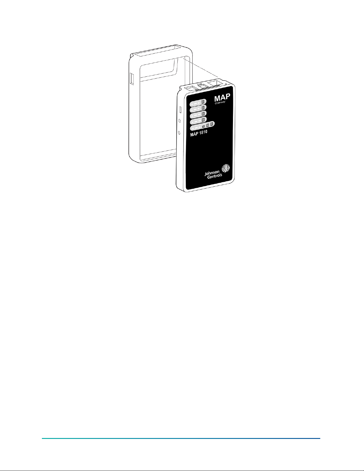
Figure 1: Portable MAP Gateway and Protective Shell
Mounting
Permanent Mounting
When used in a stationary configuration, the MAP Gateway is permanently mounted using the
provided bracket with the stationary MAP Gateway. We recommend the following three ways to
mount the unit: vertically (upright and flush), horizontally (sideways and flush), or perpendicularly
(perpendicular to the wall). This flexibility allows the unit to be mounted in a way that minimizes
spacial constraints and maximizes placement options for optimal wireless signal strength.
The unit should be mounted in such a way that labels can be read if they are visible. (For example,
do not mount the unit upside down, which puts the labels upside down.)
Location Considerations
Observe the following guidelines when mounting the MAP Gateway:
• Mount the MAP Gateway in areas free of corrosive vapors and observe the environmental
limitations listed in the Technical Specifications section of this document.
• Objects (including ductwork, cabinets, doors, and glass) can impede the wireless signal.
Minimize the number of objects between the connected computer or mobile device computer,
and the MAP Gateway. Use line of sight, if possible.
• Metal objects (such as cabinet doors, enclosures, and pipes) and concrete objects (such
as pillars, walls, and ceilings) may limit Wi-Fi service. To accommodate potential structural
obstacles on site, the MAP Gateway can be mounted flush against the wall or perpendicular to
it.
• The MAP Gateway is not rated for outdoor mounting.
9Mobile Access Portal Gateway Installation Guide
Page 10
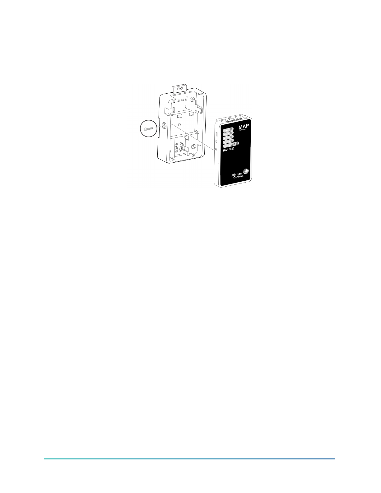
Locking Screw (Stationary Unit Only)
Regardless of which mounting configuration is used, a locking screw is used to secure the unit into
the mounting bracket. Do not overtighten the locking screw.
Figure 2: Stationary Mounting with Locking Screw
Permanent Mounting Locations
The mounting bracket can be attached to a 35 mm (1-1/8 in.) DIN rail or a flat, vertical surface.
Mounting the unit on a ceiling or in a way that positions the front of the unit facing down is not
recommended.
Although the bracket has two mounting clips, only the bottom clip snaps inward. The top clip is
permanently locked in the outward position, and it can be used as an additional hole for screwing
the bracket into place. If not utilized for DIN rail or surface mounting, the top and bottom clips may
be removed from the mounting bracket.
DIN Rail Mounting
To mount the bracket on a DIN rail:
1. Securely mount a 7.5 cm (3 in.) or longer section of 35 mm (1-1/8 in.) DIN rail in the required
space.
2. On the bracket, pull the bottom mounting clip outward to the extended position.
Mobile Access Portal Gateway Installation Guide10
Page 11
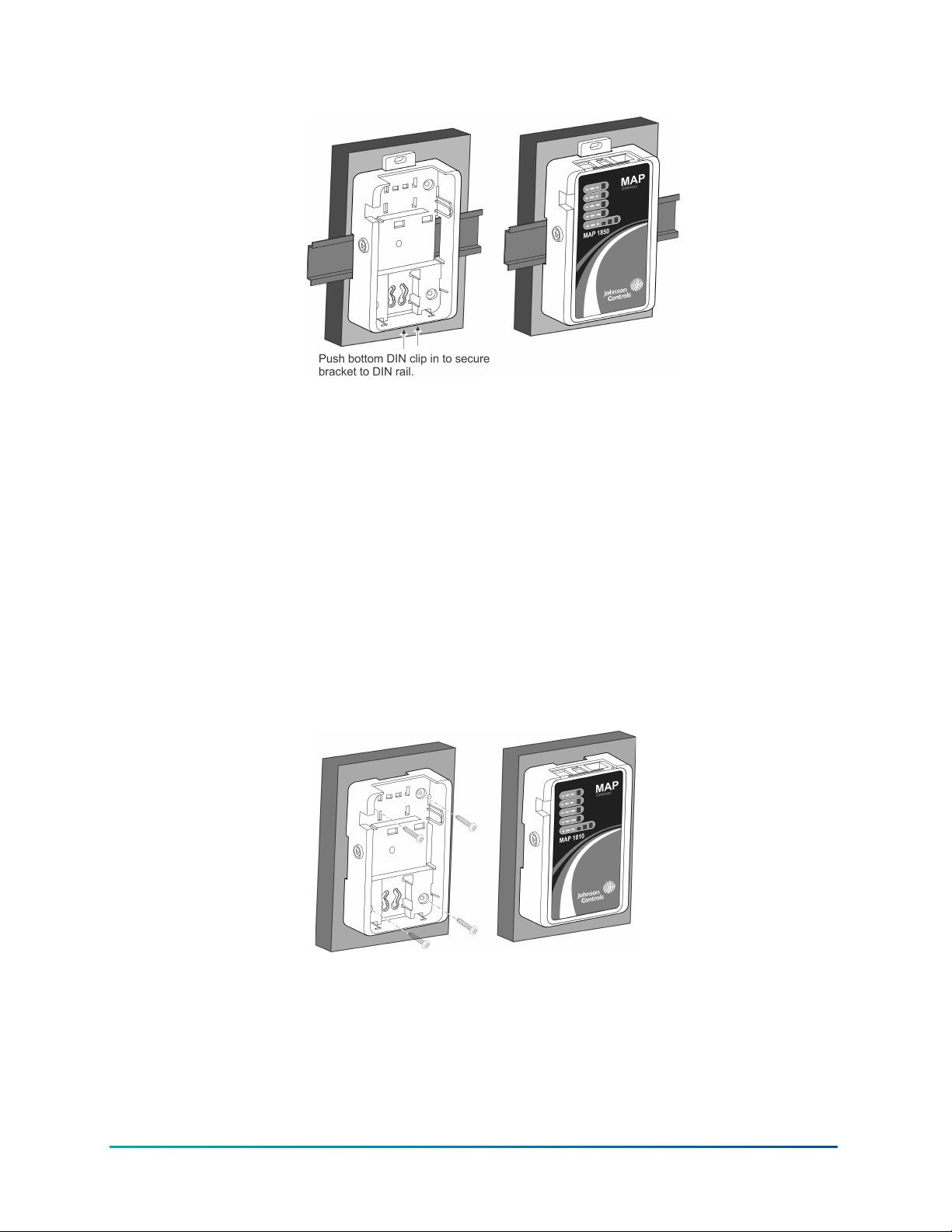
Figure 3: Positioning the Bracket on a DIN Rail
3. Hang the bracket on the DIN rail by the hooks at the top of the DIN rail channel (on the back of
the bracket), and position the bracket snugly against the DIN rail.
4. Push the bottom DIN (mounting) clip inward to secure the mounting bracket on the DIN rail.
5. Place the MAP Gateway unit in the bracket and secure it with the locking screw.
Wall Mounting
The bracket may be mounted using screw holes on the back of the bracket (so that the back of the
unit is flush with the mounting surface), using the screw holes on the side of the bracket, or using
the holes in the DIN rail clips. This orientation helps accommodate on-site constraints. Screw hole
locations are illustrated in Figure 7, Figure 8, and Figure 9.
The screw types needed to mount the unit depend upon the surface to which the unit is mounted.
The screw holes on the MAP Gateway can accommodate M3.5 and #6 screws.
For information on location considerations for maximizing signal strength, see the Mounting
section.
Figure 4: Sample Permanent Mounting, Back-side Screws
11Mobile Access Portal Gateway Installation Guide
Page 12

Figure 5: Sample Permanent Mounting, Side Screws
Figure 6: Sample Permanent Mounting, DIN Rail Screw Holes
To mount the bracket on a flat surface (such as a wall):
1. Pull the bottom mounting clip outward to the extended position.
2. Mark mounting hole locations on the wall using the dimensions shown in Figure 7, Figure
8, or Figure 9; or hold the bracket against the wall and mark the hole locations through the
mounting clips.
Note: The position of the location holes depends on whether the bracket is mounted
horizontally or vertically.
Mobile Access Portal Gateway Installation Guide12
Page 13
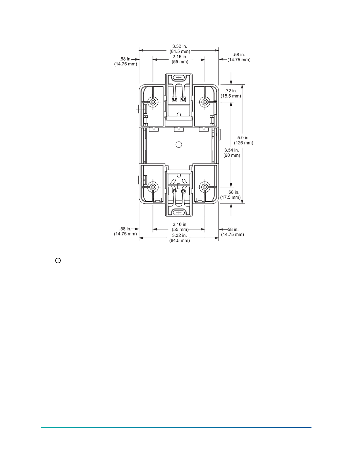
Figure 7: Mounting Holes, Flat Mounting
Note: The screw holes on the MAP Gateway can accommodate M3.5 and #6 screws.
13Mobile Access Portal Gateway Installation Guide
Page 14

Figure 8: Mounting Holes, Side Mounting
Note: The screw holes on the MAP Gateway can accommodate M3.5 and #6 screws.
Mobile Access Portal Gateway Installation Guide14
Page 15

Figure 9: Mounting Holes, Flat Mounting, DIN Rail Screws
Note: The screw holes on the MAP Gateway can accommodate M3.5 and #6 screws.
3. Drill holes in the wall based on the locations marked in the preceding step, and insert wall
anchors for each hole (if necessary).
4. Hold the bracket in place, insert the screws through the mounting clips and into the screw
holes, and then carefully tighten all screws.
Important: Do not overtighten the mounting screws. Overtightening the screws may
damage the mounting clips or bracket.
5. Place the MAP Gateway unit in the bracket and secure the bracket with the locking screw.
15Mobile Access Portal Gateway Installation Guide
Page 16

Wiring
Wiring Consideration and Guidelines
Observe the following guidelines when wiring the MAP Gateway:
• Do not allow the MAP Gateway to hang from a cable connection.
• Provide some slack in the cable between the MAP Gateway and the controller or other device
to which you are connecting.
SA/FC Port
The MAP Gateway has one RS-485 FC/SA bus port that connects through a supplied 6-pin modular
jack and cable assembly. For data transmission and voltage specifications, see the Technical
Specifications section.
Do not plug the SA/FC connector into a standard phone jack.
See the Connecting to the MAP Gateway Wi-Fi Network section for the location of the
communications terminal on the MAP Gateway.
Figure 10: SA/FC Port Pin
Field Bus Communications Connections
About this task:
To connect the MAP Gateway to the SA/FC field bus for communication, connect one end of the
RJ-12 cable to the MAP Gateway and the other end of the cable to a controller or network sensor.
Note: The MAP Gateway has a dedicated MS/TP bus address of 03. The number of MAP
Gateway units that can be connected simultaneously to one MS/TP bus depends on
the number of FC and SA ports available and connected to the bus. The MS/TP bus can
accommodate one MAP Gateway on the FC bus and one MAP Gateway for each SA bus
connected to the trunk.
Performance of the MAP Gateway varies based on the number of SA bus connections and
amount of traffic.
USB Port
The USB port on the MAP Gateway is a 5-pin, Micro-B peripheral serial port that conforms to
the USB 2.0 standard. The MAP Gateway USB port is for connecting to a computer to perform
substantial software updates. Refer to the MAP Update Tool (LIT-12012979) for details on performing
Mobile Access Portal Gateway Installation Guide16
Page 17

updates using the USB port. When the MAP Gateway is connected and powered from the USB port,
FC/SA bus functions are not available.
Note: The USB connection on the MAP Gateway is not designed for constant use. The USB port
should be used only when needed.
Table 1: USB Port Pin Designations
Pin Number (Both
Ends of Cable)
1 +5 VDC
2 Data -
3 Data +
4 No Connection
5 Ground
Signal Name
Ethernet Port
The Ethernet port on the MAP Gateway is an 8-pin RJ-45 jack. The maximum allowable cable length
is 100 m (328 ft).
External Power Supply Connections
Important: If you install the SC-AP Gateway inside an outdoor chiller, you must use the SCEquip card for power.
To connect the MAP Gateway using the supplied external power source:
1. Connect the 15 VDC output connector of the power supply to the power supply port of the
MAP Gateway.
NOTICE
Risk of Property Damage.
Do not apply power to the system before checking all wiring connections. Short circuited or improperly
connected wires may result in permanent damage to the equipment.
Risque de dégâts matériels.
Ne pas mettre le système sous tension avant d'avoir vérifié tous les raccords de câblage. Des fils
formant un court-circuit ou connectés de façon incorrecte risquent d'endommager irrémédiablement
l'équipement.
2. Connect the power supply to the supplied power cord.
3. Plug the power cord into a 100 to 240 VAC outlet.
Important: Power should only be applied and removed by connecting and disconnecting
the power cord from the 100–240 VAC outlet. Applying or removing power by connecting or
disconnecting the 15 VDC connector can damage the unit.
17Mobile Access Portal Gateway Installation Guide
Page 18

WARNING
Risk of Electric Shock.
Disconnect or isolate all power supplies before making electrical connections. More than one
disconnection or isolation may be required to completely de-energize equipment. Contact with
components carrying hazardous voltage can cause electric shock and may result in severe personal
injury or death.
Risque de décharge électrique.
Débrancher ou isoler toute alimentation avant de réaliser un branchement électrique. Plusieurs
isolations et débranchements sont peut-être nécessaires pour -couper entièrement l'alimentation
de l'équipement. Tout contact avec des composants conducteurs de tensions dangereuses risque
d'entraîner une décharge électrique et de provoquer des blessures graves, voire mortelles.
Figure 11: MAP Gateway with Sample External Power Supply
Operation
Accessing Smart Equipment Using the MAP Gateway
When the MAP Gateway is physically connected to an MS/TP network, users can have access to
Smart Equipment devices. The MAP Gateway can connect through the SA bus or through the FC
bus.
Through the Sensor Actuator (SA) Bus
If the MAP Gateway is connected through the SA bus (for example, point A on Figure 12), it can
access the SE device and all SE devices on that device's FC bus when the FcBusMode is set to Wired
Field Bus (BACnet MSTP) in the UCB display menu of the units connected to the FC bus network.
You can connect the MAP Gateway through the local SA Bus jack on the equipment control board.
Or, if a Net Sensor is installed, you can connect the MAP Gateway directly to the RJ-12 jack on the
Net Sensor.
Through the Field Controller (FC) Bus
If the MAP Gateway is connected through the FC bus (point B on Figure 12), it has access to
SE devices on that FC bus only when the FC bus protocol is BACnet MSTP. For individual units
Mobile Access Portal Gateway Installation Guide18
Page 19

connected to the FC bus network, the FcBusMode is set to Wired Field Bus (BACnet MSTP) in the
UCB display menu. The MAP Gateway can be connected to the FC bus through the RJ-12 connector
on the Field Bus card of the smart equipment. Or, using an RJ-12 to Terminal Block Adapter (MPSTAFBA-0), you can connect the MAP Gateway directly to the field bus.
To interact with a device or product on the network (to view devices, setpoints, or view alarms),
users select the device using a web-enabled device that is connected to the MAP Gateway Wi-Fi
network. To use the network, users must have a web-enabled device that uses a supported Internet
browser. For information on connecting to the network, see Connecting to the MAP Gateway Wi-Fi
Network.
Figure 12: Accessing Smart Equipment
19Mobile Access Portal Gateway Installation Guide
Page 20

Connecting to the MAP Gateway Wi-Fi Network
Important: If you are going to use the MAP Gateway on Ethernet, you must plug it into
external power before you attach the field bus adapter.
1. Connect the FC/SA port of the MAP Gateway to the sensor bus or field busport of the
equipment controllerusing the supplied RJ-12 cable (portable model) or field bus adapter
(stationary model) (Figure 13). The MAP Gateway's LEDs flash, indicating that the device
is initializing. When the Fault LED turns off and the Wi-Fi LEDs flash in succession, the MAP
Gateway is ready to use.
Figure 13: Connecting the MAP Gateway to Your Equipment
2. In the Wi-Fi settings of your device or laptop, connect to the MAP Gateway Wi-Fi network using
your default credentials. These credentials are included on a sticker in the MAP Quick Start
Guide (Part No. 24-10737-16) that came with your device.
3. Direct your browser to www.mapgwy.com to open the MAP Gateway browser interface.
Note: MAP Gateway ships with a private mapgwy.com SSL certificate installed to ensure
secure communication with the MAP Gateway. However, this certificate does not indicate
that it is trusted in a browser. If you wish to install your own certificate, refer to Adding a
Private Key and Certificate to MAP Gateway in the Mobile Access Portal Gateway Network and
IT Guidance Technical Bulletin (LIT-12012015).
4. Read and accept the MAP Gateway license agreement.
5. The first time you log in to the MAP Gateway, the Change Password and Passphrase web page
appears. You must change the Admin password and Wi-Fi passphrase.
Important: After you change the Wi-Fi passphrase or SSID, the webserver restarts and
you must rejoin the MAP Gateway Wi-Fi network using the new passphrase. On some
mobile devices, you must select and forget the original MAP Gateway Wi-Fi network
before rejoining the network with the new passphrase.
Change the default password in the New Admin Password field. Confirm the change by
entering the new password in the Verify New Admin Password field
Change the Wi-Fi Passphrase in the New Wi-Fi Passphrase field and click Save.
Once the MAP Gateway is physically connected to the MS/TP network, all devices on the network
that have an equipment number are available
To interact with a device on the network (to view points or set points), click on that device in the
device list using the mobile device that is connected to the MAP Gateway.
Mobile Access Portal Gateway Installation Guide20
Page 21

Reset Button Operation and Descriptions
If you lose your password or if you want to restore the unit to factory defaults, the MAP Gateway
offers two reset functions: a Network Reset function that resets Wi-Fi and Ethernet settings, and
a Reset to Factory Defaults function that resets all unit settings (including user profiles). Reset to
Factory Defaults also resets your SSL certificate to the Johnson Controls® self-signed certificate that
is in the device when it comes from the factory.
The Network Reset function is intended for individuals who forget their Wi-Fi connection
information, and the Reset to Factory Defaults function is for use by administrators who may
want to clear all user profiles from a device. For information on resetting the unit, see Table 2.
Important: To use a unit that is reset to factory defaults, you must have the default login
information supplied in the Quick Start Guide that shipped with the unit. This includes the
factory SSID and passphrase. The Reset to Factory Defaults function does not change the
version of the application. If you did a software upgrade, the MAP Gateway remains at the
upgraded version rather than resetting to the version that it was running when it left the
factory.
The reset button is on the back of the device, and it is embedded into the MAP Gateway housing so
that it cannot be activated by accident. To reach the reset button, use a small screwdriver or similar
tool, see Figure 14.
• If you are connected to the network when you use the reset button, you are disconnected.
• If you press the reset button for more than 9 seconds, the reset operation is cancelled.
• If a fault condition already exists, the reset button is disabled.
21Mobile Access Portal Gateway Installation Guide
Page 22

Figure 14: Using the Reset Button
Mobile Access Portal Gateway Installation Guide22
Page 23

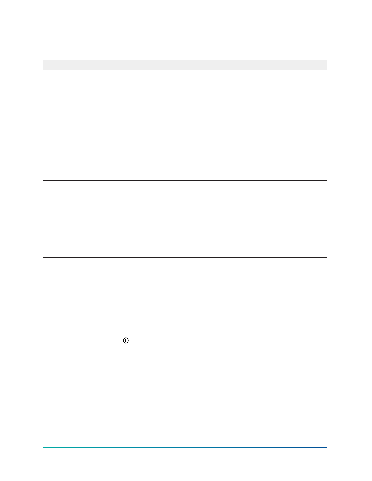
Table 2: Reset Button Operation and Descriptions
Reset Function Reset Operation
1. Press and hold the reset button for 2 seconds. The Fault LED
displays Slow Flicker behavior.
2. Release the reset button within 3 seconds. The Fault LED continues
Slow Flicker behavior.
Reset Wi-Fi and
Ethernet Settings
(Network Reset)
Reset to Factory
Defaults (Resets
all unit settings,
including user profiles)
3. Press and immediately release the reset button to confirm that you
wish to reset Wi-Fi and Ethernet settings. (If you do not press the
reset button to confirm within 5 seconds, the reset operation is
cancelled.)
The Wi-Fi (SSID and passphrase) and Ethernet settings are reset to
factory defaults. The LEDs stop flickering for 2 seconds, and then
the LEDs return to normal operation, based on the current state of
the device.
1. Press and hold the reset button for 6 seconds. The Fault LED
displays Slow Flicker behavior at first, then Fast Flicker behavior.
2. Release the reset button within 3 seconds of the change to Fast
Flicker. The Fault LED continues to Fast Flicker.
3. Press and immediately release the reset button to confirm that
you wish to reset to factory defaults. (If you do not press the
reset button to confirm within 5 seconds, the reset operation is
cancelled.)
4. All unit settings are reset to factory defaults. The LEDs stop flashing
for 2 seconds, and then the LEDs return to normal operation, based
on the current state of the device.
Note: For information on LED designations and flicker behavior, see Table 3.
Status Indication LEDs
The MAP Gateway communicates status using LEDs to indicate the following functional states:
• Power
• Fault
• SA/FC bus communication
• Ethernet communication
• Wi-Fi strength
See Table 3 for a comprehensive list of MAP Gateway LED functional information.
23Mobile Access Portal Gateway Installation Guide
Page 24

MAP Gateway LED Designations and Descriptions
Table 3: LED Designations and Descriptions
LED Name Color Normal Descriptions/Other Conditions
Off = No power
Power Green
On Steady (no
flashing)
On Steady = Power supplied by
primary voltage
Off = No faults/normal operation
On Steady = Missing hardware,
missing software, operating system
has not yet initialized, or reset is in
progress.
Fault Red Off
SA/FC Bus Green Flicker
Ethernet Green On Steady
Wi-Fi Yellow On Steady
Slow Flicker (1 blink per second) =
Software upgrade in progress
Medium Flicker (2 blinks per
second) = Startup sequence
Fast Flicker (5 blinks per second) =
Fault
Off = Receiving data
On Steady = Transmitting data
Flicker = Data is being transmitted
on the network
Off = Communication not
established
On Steady = Communication
established
Flicker = Data transmission
Wi-Fi strength is indicated by the
number of LEDs that are lit, with
one lit LED indicating weak wireless
signal strength (between 1% and
49%) and three lit LEDs indicating
excellent wireless signal strength
(at least 75%).
Off = No Wi-Fi signal
LED Test Sequence at Startup
About this task:
During startup, the MAP Gateway automatically initiates a self-test to verify proper operation of the
unit. Immediately after connecting supply power, the following LED lighting sequence occurs:
1. The Power LED turns on and stays lit.
Mobile Access Portal Gateway Installation Guide24
Page 25

2. The Fault LED indicator flashes for approximately 40 seconds, then turns off when the MAP
Gateway is fully functional.
3. The Wi-Fi LEDs light up in succession (scanning), indicating that the MAP Gateway is waiting
for a device to join its Wi-Fi network.
Repair Information
If the MAP Gateway fails to operate within its specifications, replace it. The MAP Gateway is not a
serviceable product; however, it does support software updates to enable feature enhancements.
For a replacement unit, software updates, or accessories, contact the nearest Johnson Controls
representative.
Do not open the MAP Gateway housing. The MAP Gateway has no user-serviceable parts inside.
The MAP Gateway does not require periodic field maintenance.
25Mobile Access Portal Gateway Installation Guide
Page 26

Troubleshooting
Table 4: Launch Issues Troubleshooting Information
Problem Resolution
Reason
Device behavior can vary based on the device and Internet browser
You are not directed to the
MAP Gateway login page
when you launch a web
browser.
After the controller or HVAC
device to which a MAP
Gateway is connected is
upgraded, the connected
MAP Gateway no longer
displays active or current
data.
Every time I install the SSL
certificate on my device, it
asks meto re-install it. What
should I do?
in use. For instance, some devices cache browser information and
do not automatically redirect users to the MAP Gateway login page
when the browser is launched.
Resolution
Direct your browser to www.mapgwy.com.
Unplug the MAP Gateway from the sensor actuator (SA) or field
controller (FC) bus, then plug the MAP Gateway back in.
1. Verify that the time on your clientdevice is correct. If the device
time is not current (for example, after ahard reset), close the
browser, set the time, and then try toinstall the certificate.
Note: You must time sync the device if the local time on SCEquip data does not match the correct local time. Do this in the
BACnet time sync menu. The time on the browser device is then
sent to the SC-Equip to sync up the times.
When I install the SSL key
or certificate, I receive the
message Error Saving SSL
Settings.
2. Check your Web Browser Settingsand verify that Cookies are
enabled.
Reason
When an SSL key or certificate is very corrupted, the SSL page
detects it and alerts you to the corrupted key or certificate.
However, if the corruption is minor, for example, an extra space
was copied while installing the certificate or a character was missed,
the UI does not detect the problem and allows the corrupted key
or certificate to be saved. The server detects the error and returns
the Error Saving SSL Settings message. While this correctly
prevents the bad key or certificate from being used, it does not
inform you as to the source of the problem.
Resolution
In this case, reinstall the SSL key or certificate as described in the
Mobile Access Portal Gateway Network and IT Guidance Technical
Bulletin (LIT-12012015).
Mobile Access Portal Gateway Installation Guide26
Page 27

Table 4: Launch Issues Troubleshooting Information
Problem Resolution
Reason
The MAP Gateway requires an external power supply. The LC
IOM2723, IOM3733, and IOM3723 only have a 4 pin plug terminal
When I connect a MAP
Gateway to an LC IOM, it
does not power on.
that does not provide power.
Resolution
• Connect the MAP gateway through the SA or FC bus when
connecting the IOM to a field controller.
• Use an external power source for any MAP Gateway that you
are connecting to the IOM.
Accessories
Table 5: MAP Gateway Accessories
Code Description
MP-PRTKIT Portable Kit (Includes MAP Gateway, RJ-12 cable, shell, and lanyard.)
MP-STAKIT-0
MP-STAKIT-0Hx
MP-STAFBA-0
TL-PWRKIT-0A Optional power supply (A = US and Canada).
TL-PWRKIT-0B
TL-PWRKIT-0D
Stationary Cradle Only (Includes mounting bracket and field bus
adapter.)
Stationary Cradle Kit (Includes mounting bracket, field bus adapter,
and 100–240 VAC line voltage power supply.)
Field Bus Adapter (Includes RJ-12 to 4-position Terminal Block
Adapter. Used for interfacing directly to MS/TP Field Bus.)
Optional power. (B = Australia, New Zealand, China, Turkey,
Germany, Hong Kong, Netherlands, Qatar, Saudi Arabia, Thailand,
UAE, UK).
Optional power supply with interchangeable input blades for North
America, Europe, UK, Australia, and China. Input: 90 to 264 VAC,
50/60 Hz.
Note: TL-PWRKIT-0A and TL-PWRKIT-0B are not rated for outdoor temperatures.
27Mobile Access Portal Gateway Installation Guide
Page 28
Technical Specifications
Table 6: MAP Gateway
Specification Description
Product Code TL-MAP1810-OP, TL-MAP1810-OPE, TL-MAP1810-OPA:TL-MAP1810-
OPA, TL-MAP1810-0PM, TL-MAP1810-0PS, TL-MAP1810-0PI: Portable
MAP Gateway - includes MAP Gateway, RJ-12 cable, bumper guard, and
lanyard.
TL-MAP1810-0Sx: Stationary MAP Gateway - includes MAP Gateway,
field bus adapter, mounting bracket, and AC power supply. (Adapters
for the power supply may vary by country.)
Power Consumption From SA/FC bus: 15 VDC at 2.7 VA maximum
Ambient Temperature
Conditions
Ambient Humidity
Conditions
Transmission Power
(Typical)
Operating: 0 to 50°C (32 to 122°F)
Operating Survival: -30 to 60°C (-22 to 140°F)
Non-Operating:-40 to 70°C (-40 to 158°F)
Storage: -40 to 70°C (-40 to 158°F); 5 to 95% RH 30°C (86°F) maximum
dew point conditions
Operating: 0-50°C (32 to 122°F); 5 to 95% RH, 30°C (86°F) maximum
dew point conditions
Wireless Local Area Network (WLAN) Transmission Power:
+14.5 dBm, 54 Mbps
+12.5 dBm, 65 Mbps
WLAN Receiver
Sensitivity (Typical)
Transmission Speeds Wireless Communication:
-76 dBm, 10% packet error rate (PER), 54 Mbps
-73 dBm, 10% PER, 65 Mbps
2.4 GHz ISM bands, 802.11 b/g/n, 11/22/54 Mbps
Serial Communication (SA/FC Bus):
9600, 19.2k, 38.4k, or 76.8k bps
Note: If you connect a MAP at 4.0 or earlier to an FC bus, select
an MSTP baudrate of 38.4k bps.
Ethernet Communication:
10 Mbps, 100 Mbps
Mobile Access Portal Gateway Installation Guide28
Page 29

Table 6: MAP Gateway
Specification Description
Wi-Fi Transmission
Wi-Fi Wireless Communication:
Range (Typical)
30 m (100 ft) line-of-sight indoors; however, a typical indoor range in
an area with obstacles is 15 m (50 ft).
91 m (300 ft) line-of-sight outdoors
WLAN Range Performance:
0–50 ft = Excellent
50–100 ft = Good
100–300 ft = Weakest, approaching out of range
Wi-Fi Wireless Security WPA2-PSK TKIP (Wi-Fi Protected Access Pre-Shared Key Mode Temporal
Key Integrity Protocol)
WPA2-EAP-PEAP
WPA2-EAP-TLS
Network and Serial
Interfaces
One SA/FC port (6-pin port; connects with ZFR1820/1823. Can be
extended to 30 m (100') if necessary)
One USB port (Micro-B port; 2.0; supports Open Host Controller
Interface [Open HCI] specification)
Dimensions
Unit alone: 120 x 70 x 24.5 mm (4-23/32 x 2-3/4 x 31/32 in. when used
vertically)
(H x W x D)
Unit in shell: 128 x 75 x 29.5 mm (5-1/32 x 2-61/64 x 1-5/32 in. when
used vertically)
Housing White Acrylonitrile butadiene styrene (ABS) bracket, plenum-rated
Weight MAP Gateway alone: 0.10 kg (0.22 lb)
MAP Gateway in shell: 0.15 kg (0.33 lb)
Note: Weights do not include any peripheral components such as
cables, lanyard, or an external power supply.
Web Browser
Requirements for
Computers and
Handheld Devices
Computer:
Google®Chrome™ 54 and above is the preferred browser for MAP.
Windows Internet Explorer® 11, and Apple®Safari® 8 and above are
also supported.
Handheld Device:
The handheld device must be running iOS version 8.0 or later on an
Apple® iPhone® or iPod touch®; Android™ versions 5.1 or later; or
using the browser Google Chrome 54 or above.
Note: Other web browsers may display the UI, but the
functionality is not guaranteed.
Purpose of control Operating control
29Mobile Access Portal Gateway Installation Guide
Page 30
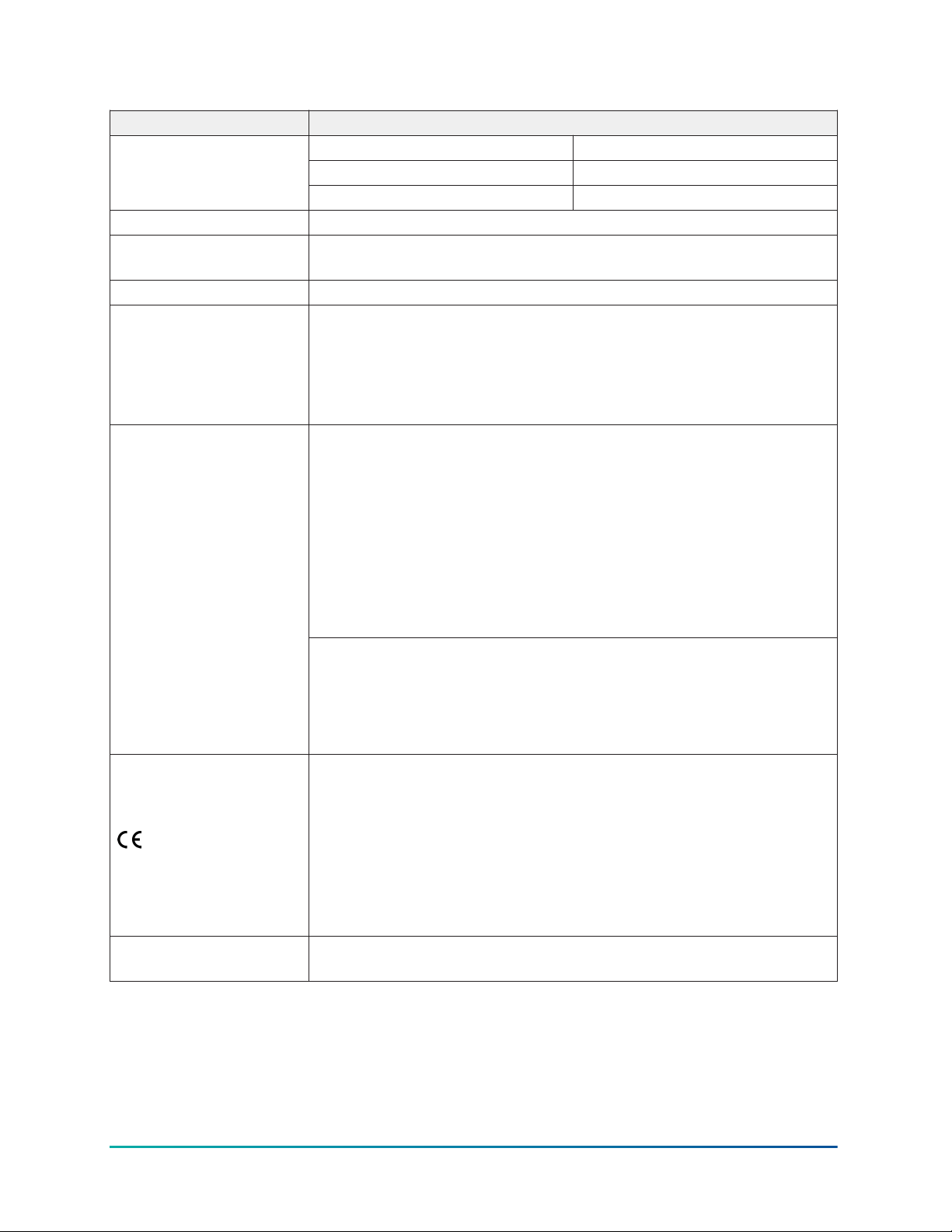
Table 6: MAP Gateway
Specification Description
Construction of control
and whether the
control is electronic
Suffix Field "V" digits Type
S, C, E Independently mounted
P Free Standing / Hand Held
TYPE 1 or TYPE 2 action TYPE 1
External Pollution
Pollution Degree 2
Situation
Rated impulse voltage 330 V
15 VDC External Power
Supply (Not required
if module is provided/
shipped with power
supply)
Terminal J4:
SELV; Class 2 or LPS (Limited Power Source) ITE Equipment Power
Supply
Terminal J1:
Intended for connection to Johnson Controls field controllers
supporting the standard JCI SA Bus implementation
Compliance
United States UL Listed File E107041, UL 60730-1, Automatic Electrical
Controls; UL 2043 (Stationary version only), Suitable for Use in Other
Environmental Air Space in Accordance with Section 300.22, (C) of the
National Electric Code.
Transmission Complies with FCC Part 15.247 Regulations for Low Power
Unlicensed Transmitters
Transmitter FCC Identification: OEJ-MAPWIFI
FCC Compliant to CFR 47, Part 15, Subpart B, Class A
Canada: Industry Canada IC: 279A-MAPWIFI
IC: RSS-210
cUL Listed File E107041, CAN/CSA E60730-1, Automatic Electrical
Controls
Europe: CE Mark—Johnson Controls declares that this product is
in compliance with the essential requirements and other relevant
provisions of the Radio Equipment Directive (RED), LVD Directive, and
the EMC Directive.
CE Emission: EN61000-6-3: 2007; Generic standards for residential,
commercial, and light-industrial environments. ETSI EN 301
489-1:2001-09, ETSI EN301 489-3:2001-11 (Class 2), IEC 60730-1/
EN60730-1
Australia and New Zealand: RCM Mark, Australia/NZ Emissions
Compliant.
Mobile Access Portal Gateway Installation Guide30
Page 31
Table 6: MAP Gateway
Specification Description
Mexico: La operación de este equipo está sujeta a las siguientes dos
condiciones: (1) es posible que este equipo o dispositivo no cause
interferencia perjudicial y (2) este equipo o dispositivo debe aceptar
cualquier interferencia, incluyendo la que pueda causar su operación
no deseada.
The operation of this equipment is subject to the following two
conditions: (1) it is possible that this equipment or device may not
cause harmful interference, and (2) this equipment or device must
accept any interference, including interference that may cause
undesired operation.
IFT, Número: NYCE/CT/0471/17/TS
Brazil: According to application guidance "INSTRUMENTODE GESTÃO
DOC.IG/06 - v.02 DATA: 15/10/2006"
Para atender os limites de radiofrequencia estabelecidos, a distância
entre a antena ou antenas e o usuário não deve ser inferior a 20cm.
To comply with RF exposure limits established, the distance between
the antenna or antennas and the user should not be less than 20 cm.
ANATEL: 03298-17-06174 Para consultas, visite: www.anatel.gov.br
Argentina: CNC,Número de Inscripción: C-17791
Jamaica: This product has been Type Approved by Jamaica: SMA -
MAP18
Paraguay: CONATEL, Número del Registro:2017-06-I-0000165
The performance specifications are nominal and conform to acceptable industry standard. For
application at conditions beyond these specifications, consult the local Johnson Controls office. Johnson
Controls shall not be liable for damages resulting from misapplication or misuse of its products.
Product warranty
This product is covered by a limited warranty, details of which can be found at
www.johnsoncontrols.com/buildingswarranty.
Software terms
Use of the software that is in (or constitutes) this product, or access to the cloud, or hosted
services applicable to this product, if any, is subject to applicable end-user license, opensource software information, and other terms set forth at www.johnsoncontrols.com/
techterms. Your use of this product constitutes an agreement to such terms.
31Mobile Access Portal Gateway Installation Guide
Page 32

Single point of contact
APAC Europe NA/SA
JOHNSON CONTROLS
JOHNSON CONTROLS
JOHNSON CONTROLS
C/O CONTROLS PRODUCT MANAGEMENT
NO. 32 CHANGJIJANG RD NEW DISTRICT
WUXI JIANGSU PROVINCE 214028
CHINA
WESTENDHOF 3
45143 ESSEN
GERMANY
Contact information
Contact your local branch office: www.johnsoncontrols.com/locations
Contact Johnson Controls: www.johnsoncontrols.com/contact-us
507 E MICHIGAN ST
MILWAUKEE WI 53202
USA
© 2021 Johnson Controls. All rights reserved. All specifications and other information shown were current as of document
revision and are subject to change without notice.
 Loading...