

Johnson Controls TEC3000 Series, TEC3322-1 Series, TEC3622-1 Series, TEC3623-1 Series, TEC3022-1 Series Quick Start Manual
...Page 1

TEC3000 Series Networked and Wireless Proportional Fan
(barcode for factory use only)
24-11353-00028, Rev. C
*241135300028C*
Coil and Individual Zone Thermostat Controllers with
Dehumidification Capability
Quick Start Guide
TEC3322-1x-xxx, TEC3323-1x-xxx, TEC3622-1x-xxx, TEC3623-1x-xxx, TEC3022-1x-xxx, TEC3023-1x-xxx
Refer to the QuickLIT website for the most up-to-date version of this document.
Part No. 24-11353-00028, Rev.
Issued May 2019
North American emissions compliance
United States
This equipment has been tested and found to comply with the limits for a Class B digital device, pursuant to Part
15 of the FCC Rules. These limits are designed to provide reasonable protection ag ainst har mful inter fere nce in
a residential installation. This equipment generates, uses and can radiate radio frequency energy and, if not
installed and used in accordance with the instructions, may cause harmful interference to radio communications.
However, there is no guarantee that interference will not occur in a particular installation. If this equipment does
cause harmful interference to radio or television reception, which can be determined by turning the equ ipment off
and on, the user is encouraged to try to correct the interference by one or more of the following measures:
• Reorient or relocate the receiving antenn a .
• Increase the separation between the equipment and receiver.
• Connect the equipment into an outlet on a circuit different from that to which the receiver is connected.
• Consult the dealer or an experienced radio/TV technician for help.
Canada
C
This Class (B) digital apparatus meets all the requirements of the Canadian Interference-Causing Equipment
Regulations.
Cet appareil numérique de la Classe (B) respecte toutes les exigences du Règlement sur le matériel brouilleur
du Canada.
Installation
Parts included
• One TEC3000 Series Thermostat Controller with integral mounting base
• One installation instructions sheet
Location considerations
For networked models, locate the TEC3000 Series Thermostat Controller:
• On a partitioning wall, approximately 5 ft (1.5 m) above the floor in a location of average temperature, allowing
for vertical air circulation to the TEC
• Away from direct sunlight, radiant heat, outside walls, outside doors, air discharge grills, stairwells, and
b
ehind doors
• Away from steam or water pipes, warm air stacks, unconditioned areas (not heated or cooled), or sources of
electrical interference
• In a clear path between the integrated passive infrared (PIR) occupancy sensor (if equipped) and the spac
ing monitored
be
from
e
TEC3000 Series Networked and Wireless Proportional Fan Coil and
Individual Zone Thermostat Controllers with Dehumidification Capability
Quick Start Guide
1
Page 2
For wireless models, also locate the thermostat controller:
• Outside of a recessed area, metal enclosure, or shelving unit
• On the same building level as the other wireless devices on the same personal area network (PAN)
• At least 2 in. (51 mm) away from any metal obstruction
• In the direct line of sight to other wireless devices on the same PAN. Signal transmission is best if the path
between the TEC3000 and other wireless devices is dire ct as pos sible . Lin e of sigh t is desir abl e but no t
required. See Table 1 for recommended and maximum distances.
• Away from metal and large solid obstructions (including equipment r ooms and elevator shafts and concrete or
brick walls) between the TEC3000 and the ZFR Pro Router/Repeater or ZFR Pro Coordinator Radio
• Within range of two or more wireless devices on the same PAN. Redundancy in the layout provides the best
reliability in wireless installations
• At least 20 ft (6 m) from a microwave oven
For integrated passive infrared (PIR) models, be sure that the thermostat controller is located centrally, where
occupant movement is frequent. Ensure that the unit is not blocked by a plastic tamper resistant enclosure (such
as the GRD10A-608). The plastic enclosure blocks the occupancy sensing capability.
The use of insulating foam pads is required for installations where wirin g passes through th e wall to the thermostat.
For wireless models, the effective transmission range and dist ance for indoor applications vary because of wireless
signal absorption and reflection due to metal obstructions, walls or floors, and furniture found in typical building
interiors.
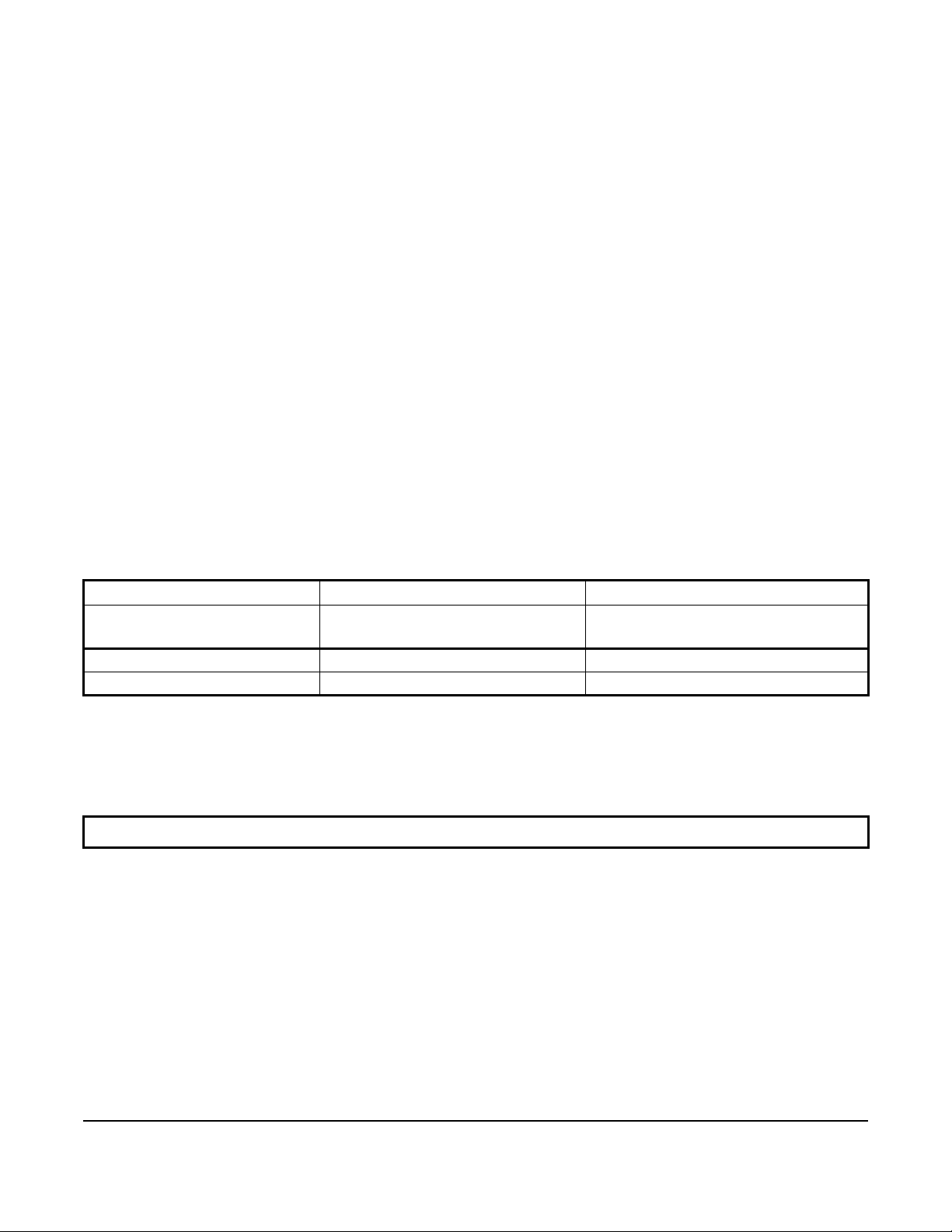
Table 1: Indoor line-of-sight transmission ranges
Range type Transmission distance
WNC Coordinator Radio,
ZFR Pro Repeater
Recommended 50 ft (15.2 m) 50 ft (15.2 m)
Line of sight, maximum 250 ft (76.2 m) 100 ft (30 m)
TEC3000 Wireless Thermostat
Controller
Notes:
• Allow for sufficient clearance to insert a USB drive into the USB port
• For more details on using ZFR Pro Series communication devices, refer to the WNC1800/ZFR182x Pro
Series Wireless Field Bus System Technical Bulletin (LIT-12012356).
IMPORTANT: Only connect memory devices to the USB port. Do not use it for charging external devices.
TEC3000 Series Networked and Wireless Proportional Fan Coil and Individual Zone Thermostat Controllers with
Dehumidification Capability Quick Start Guide
2
Page 3

Figure 1: Thermostat controller
shown without occupancy sensor,
dimensions, in. (mm)
Installing the thermostat controller
1. Use a 1/16 in. (1.5 mm) Allen wrench or Johnson Controls® T-4000-119 Allen-Head Adjustment Tool (order
separately) to remove the security screw if it is installed on the top of the thermostat controller cover as
illustrated in Figure 2.
2. Pull the top edge of the cover and open the thermostat controller as illustrated in Figure 2.
IMPORTANT: The cover is not secured on the bottom. Be careful not to drop the cover.
IMPORTANT: If you are installing more than one thermostat controller, keep track of which cover attaches to
which base. The controller version ans the base version must match to ensure proper operation.
IMPORTANT: Use proper Electrostatic Discharge (ESD) precautions during installation and servicing to avoid
damage to the electronic circuits of the thermostat controller.
TEC3000 Series Networked and Wireless Proportional Fan Coil and Individual Zone Thermostat Controllers with
Dehumidification Capability Quick Start Guide
3
Page 4

Figure 2: Removing the security screw from the thermostat controller cover
(shown without occupancy sensor) (left) and removing the thermostat controller cover (right)
3. Align the thermostat controller mounting base on the wall with the security screw on the top and use the base
as a template to mark the two mounting hole locations. See Figure 3.
Notes:
• If you need to install the thermostat controller on an electrical junction box, use
2-1/2 x 4 in. (63 x 101 mm) square boxes with mud ring covers and avoid smaller 1-1/2 x 4 in.
(38 x 101 mm) square or 3 x 2 in. (76 x 51 mm) boxes. This procedure ensures that you have enough
space for cabling, if needed.
• For surface-mounted applications, use durable mounting hardware, such as wall anchors, that cannot be
easily pulled out of the mounting surface.
4. Pull approximately 6 in. (152 mm) of wire from the wall and insert the wire through the center hole in the
thermostat controller mounting base. See Figure 3.
5. Secure the mounting base to the wall surface using two mounting screws (user supplied) as illustrated in
Figure 3.
Note: Be careful not to overtighten the mounting screws.
TEC3000 Series Networked and Wireless Proportional Fan Coil and Individual Zone Thermostat Controllers with
Dehumidification Capability Quick Start Guide
4
Page 5

Figure 3: Mounting hole locations, dimensions, in. (mm) (left) and
securing the thermostat controller mounting base to the wall (right)
Note: When the unit is mounted on the wall, you can hang the front cover on the end of the back cover as
illustrated in Figure 4.
Figure 4: Hanging the thermostat controller front cover
TEC3000 Series Networked and Wireless Proportional Fan Coil and Individual Zone Thermostat Controllers with
Dehumidification Capability Quick Start Guide
5
Page 6

Wiring
When an existing thermostat controller is replaced, remove and labe l the wires to identify the terminal functions.
Risk of Electric Shock.
Disconnect the power supply before making electrical connections to avoid electric shock.
Risque de décharge électrique.
Débrancher l'alimentation avant de réaliser tout raccordement électrique afin d'éviter tout risque de décharge
électrique.
Risk of Property Damage.
Do not apply power to the system before checking all wiring connections. Short circuited or improperly conn ected
wires may result in permanent damage to the equipment.
Risque de dégâts matériels.
Ne pas mettre le système sous tension avant d'avoir vérifié tous les raccords de câblage. Des fils formant un
court-circuit ou connectés de façon incorrecte risquent d'endommager irrémédiablement l'équipement.
IMPORTANT: Make all wiring connections in accordance with local, national, and regional regulations. Do not
exceed the electrical ratings of the TEC3000 Series Thermostat Controller.
IMPORTANT: Use proper ESD precautions during installation and servicing to avoid damage to the electronic
circuits of the thermostat controller.
To wire the thermostat co nt ro ller :
1. Strip the ends of each wire 1/4 in. (6 mm) and connect them to the appropriate screw terminals as indicated in
Table 2.
Note: For more details on wiring the MS/TP Communications Bus, refer to the MS/TP Communications Bus
Technical Bulletin (LIT-12011034).
2. Attach the communication wires to the terminal block.
Note: If multiple wires are inserted into the terminals, be sure to properly twist the wires together before
inserting them into the terminal connectors.
3. Carefully push any excess wire back into the wall.
Note: Seal the hole in the wall with fireproof material to prevent drafts from affecting the ambient temperature
readings.
4. For networked models, set the bus end-of -line (EOL) termination switch to the desired location.
TEC3000 Series Networked and Wireless Proportional Fan Coil and Individual Zone Thermostat Controllers with
Dehumidification Capability Quick Start Guide
6
Page 7

The bus EOL termination switch allows you to designate the thermostat controller as the end of the Field
Controller (FC) Bus and N2 Bus. The default position is OFF. If the thermostat controller is at the end of a daisy
chain of devices on the FC Bus and N2 Bus, set the EOL switch to the ON position. See Figure 3.
5. Reattach the thermostat contro ller cove r to the mounting base (bottom side first).
IMPORTANT: Make sure you reattach the cover that corresponds to its correct base. The CPU board number
needs to match the base board number.
base that do not belong together.
6. Use a 1/16 in. (1.5 mm) Allen wrench or Johnson Controls T -4000-1 19 Allen-Head Adju stment T ool (order
separately) to reinstall the security screw on the top of the thermostat controller cover. See Figure 2 for security
screw placement.
7. Remove the protective plastic cover sheet from the display.
IMPORTANT: If the display is dirty, gently wipe it clean with isopropyl alcohol or ethyl alcohol. Do not scrub
hard as to avoid damaging the surface. Do not use other cleaners such as water, ketones, and aromatic
solvents, since they may damage the polarize r.
Notes:
• For VAV and two-pipe systems, connect the valve to the heating output.
• Only one transformer is required for each TEC.
• Power to the AUX contact comes from the reheat coil.
Otherwise, an operation error occurs after you reattach a cover and
TEC3000 Series Networked and Wireless Proportional Fan Coil and Individual Zone Thermostat Controllers with
Dehumidification Capability Quick Start Guide
7
Page 8
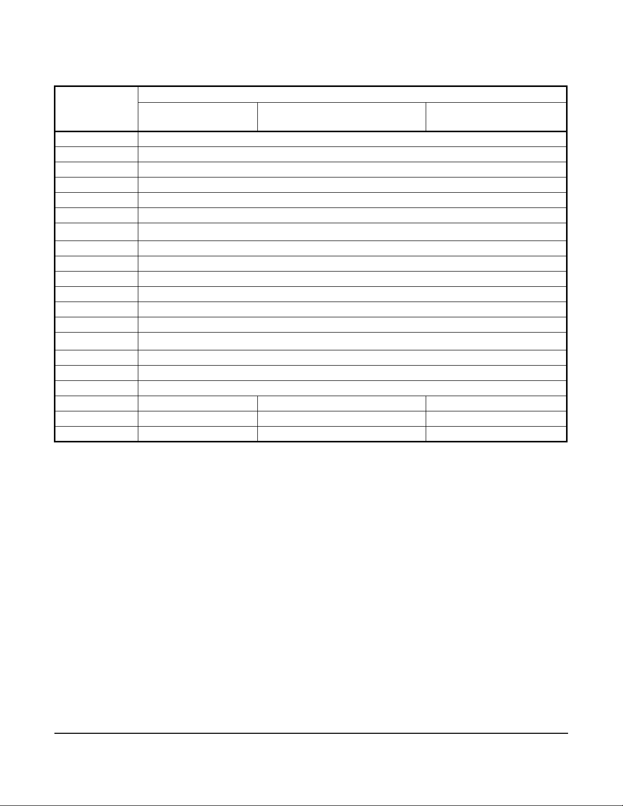
Table 2: Terminal identification (See Figure 5 for wiring diagrams)
Terminal label Function
TEC3022, TEC3023,
Proportional FC/VAV
24 V 24 VAC hot from transformer
FAN H Fan high
FAN M Fan medium
FAN L Fan low and fan on
AUX Auxiliary binary output
AUX Auxiliary power
1
COM
CLG Cooling command (configurable 0 to 10 V range)
NC No connection
NC No connection
HTG Heating command (configurable 0 to 10 V range)
RSEN Configurable analog input 1
COS Configurable analog input 2/Changeover binary switch
1
COM
VSF Variable speed fan command (configurable 0 to 10 V range)
BI-2 Configurable binary input 2
BI-1 Configurable binary input 1
NET+ N/A Not connected Field bus+/N2+
NET- N/A Not connected Field bus-/N2-
NET COM N/A Not connected Isolated common for field bus
24 VAC common from transformer
Common
TEC3322, TEC3323, Proportional
FC/VAV
TEC3622, TEC3623
Proportional FC/VAV
1. For the networked models, the common terminals, which do not include NET COM, are internally connected and can be
used for all inputs and outputs. For the wireless models, the common terminals are connected and can be used for all
inputs, outputs, and 24 VAC power.
TEC3000 Series Networked and Wireless Proportional Fan Coil and Individual Zone Thermostat Controllers with
Dehumidification Capability Quick Start Guide
8
Page 9

Figure 5: Proportional wiring diagram (See Table 2 for terminal identification)
TEC3000 Series Networked and Wireless Proportional Fan Coil and Individual Zone Thermostat Controllers with
Dehumidification Capability Quick Start Guide
9
Page 10
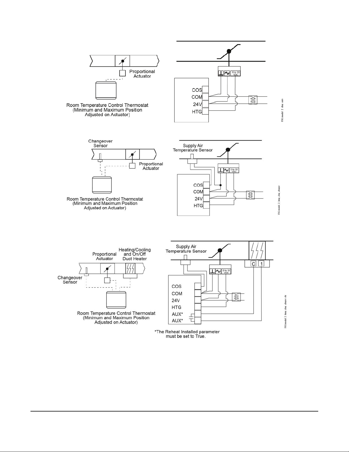
Figure 6: Proportional 0 to 10 VDC control (pressure-dependent VAV)
Figure 7: Proportional 0 to 10 VDC control (pressure-dependent VAV with changeover sensor/switch)
Figure 8: Proportional 0 to 10 VDC control
(pressure-dependent VAV with changeover sensor/switch and reheat)
TEC3000 Series Networked and Wireless Proportional Fan Coil and Individual Zone Thermostat Controllers with
Dehumidification Capability Quick Start Guide
10
Page 11

Figure 9: Floating control two-pipe heating and cooling hydronic valve control fan coil application
Two-Pipe Applications
Four-Pipe Applications
FIG:model_2_proportional
Heating/Cooling
Valve
COM
24V
CLG
HTG
Cooling
Valve
Heating
Valve
COM
24V
HTG
AUX Contact
FIG:Aux Contact Wiring
Load
Hot
19 to 30 VAC
Figure 10: Floating control two-pipe heating and cooling hydronic valve control with changeover fan coil
application
Figure 11: Proportional 0 to 10 VDC control (two-pipe and four-pipe fan coil applications)
Figure 12: AUX contact wiring
TEC3000 Series Networked and Wireless Proportional Fan Coil and Individual Zone Thermostat Controllers with
Dehumidification Capability Quick Start Guide
11
Page 12

Figure 13: Binary input wiring
FIG:Binary Input Wiring
BI1
Dry Contact
Bi2
Dry Contact
Setup and adjustments
IMPORTANT: Table 6 provides a full list of TEC3000 menu settings. Refer to TEC3000 Series Networked and
Wireless Proportional Fan Coil and Individual Zone Thermostat Controllers with Dehumidification Capability
Installation Instructions (
commonly used menus.
Overview
Figure 14 shows the thermostat controller home screen in both the light and dark themes. You can customize it to
show or hide various elements from the occupant. See Table 3 for a listing of the touchscreen icons. When screen
customization is used in conjunction with a passcode, the building owner can control which options the occupant
can access and adjust.
IMPORTANT: If lockout levels are used, some icons are hidden. Table 4 provides details of these levels.
Figure 14: Thermostat controller home screen (shown with light and dark themes)
LIT-12013162
) for step-by-step instructions on how to access and adjust the more
To switch between the modern, classic, light, and dark themes:
1. Press the Menu icon.
2. Press Settings.
3. Press Display Settings.
4. Press Change Color Theme.
5. Select one of the four options available.
Multiple pages are available on the display. The page that is currently being viewed is emphasized with a filled dot.
The other available page is displayed as an empty dot.
In the modern theme, the cooling, or blue, and heating, or ora nge, circles show whether the cooling or he ating mode
is active.
TEC3000 Series Networked and Wireless Proportional Fan Coil and Individual Zone Thermostat Controllers with
Dehumidification Capability Quick Start Guide
12
Page 13

Figure 15: Thermostat controller home screen in cooling mode (left) and heating mode (right)
Customizing the home screen
Customizing the Home screen settings include:
• Brightness • Units • Time Zone • Date
• Enable Backlight • Time • Time Format • Date Format
You can also show or hide these items on the Home screen:
• Fan Button • Off Button • Alarms • Date/Time
• Temperature • Hold Button • Occupancy Status
• Humidity • Setpoint • Unit Status
To customize the Home screen:
1. Press the Menu icon.
2. Press Display Settings.
3. Enable or disable elements of the home screen as appropriate for the building owner and occupants.
4. Set the passcode on the thermostat controller to prevent the o ccupants from changing settings th at they should
not have access to change.
Touchscreen icons
Table 3 describes the touchscreen icons on the home screen. Press and release a tou chscreen icon to activate the
TEC. Additional touchscreen icons appear based on the menu, and those icons are also described in Table 3.
Table 3: Touchscreen icons (Part 1 of 4)
Icon and icon name Description
Displays the configuration screens where
various settings may be adjusted.
Menu
Indicates that the thermostat controller has
triggered an alarm.
Alarm
TEC3000 Series Networked and Wireless Proportional Fan Coil and Individual Zone Thermostat Controllers with
Dehumidification Capability Quick Start Guide
13
Page 14

Table 3: Touchscreen icons (Part 2 of 4)
Icon and icon name Description
Powers the thermostat controller on or off.
Notes:
• This icon disables all equipment control
but does not physically power down the
unit.
• On the modern home screen, if the Unit
Unit Power
On Standby
Humidity
On Standby
Degree
On Standby
Power icon is in standby mode, the
temperature and humidity ar e al so
displayed in standby mode to indicate
that control off or standby mode is
active.
Indicates the humidity reading.
Indicates that the unit is set to degrees.
Network Communication icon indicates that
the thermostat controller detected a
supervisory controller and both are online.
Network Communication (for Networked Models)
Network communication No Signal
Radio Signal (For Wireless Models)
No Signal Low Signal Medium Signal High Signal
Arrow Up Arrow Down
Arrow Up Arrow Down
Cooling Hold
Heating Hold
No icon indicates that the thermostat
controller did not detect a supervisory
controller.
Indicates the strength of the radio signal.
Increases or decreases the cooling value
on the home screen.
Increases or decreases the heating value
on the home screen.
Indicates that cooling hold mode is
enabled. Hold mode is disabled by pressing
the button.
Indicates that heating hold mode is
enabled. Hold mode is disabled by pressing
the button.
TEC3000 Series Networked and Wireless Proportional Fan Coil and Individual Zone Thermostat Controllers with
Dehumidification Capability Quick Start Guide
14
Page 15

Table 3: Touchscreen icons (Part 3 of 4)
Icon and icon name Description
Displays the current cooling setpoint.
Indicates that Hold mode is disabled. To
enable Hold mode, press the button.
Cooling Setpoint
Displays the current heating setpoint.
Indicates that Hold mode is disabled. To
enable Hold mode, press the button.
Heating Setpoint
Displays the current setpoint temperature.
Indicates that the Show Hold button is set
to No.
Setpoint Temperature
Indicates that heating mode is selected.
Heating Mode
Indicates that cooling mode is selected.
Cooling Mode
Indicates that Auto mode is selected.
Unoccupied
Auto Mode
Fan Overrides for Single-speed Fans
On Auto Quiet
Fan Overrides for Variable-speed Fans
On Auto Quiet
Fan Overrides for Multi-speed Fans
Low Medium High Auto Quiet
Occupancy Status
Occupied
Temporarily
Occupied
Standby
OverrideOccupied
Adjusts the fan override between On, Auto,
and Quiet for single-speed fans.
Adjusts the fan override between On, Auto,
and Quiet for variable-speed fans.
Adjusts the fan override between Low,
Medium, High, Auto, and Quiet for multispeed fans.
Adjusts the occupancy between
Unoccupied, Occupied, Temporarily
Occupied, Standby, Occupancy Override,
Unoccupancy Override.
OverrideUnnoccupied
TEC3000 Series Networked and Wireless Proportional Fan Coil and Individual Zone Thermostat Controllers with
Dehumidification Capability Quick Start Guide
15
Page 16

Table 3: Touchscreen icons (Part 4 of 4)
Icon and icon name Description
Moves the display to the previous screen.
Back
Moves the display to the next screen.
Forward
Returns the display to the main home
screen.
Home
Saves the current configuration and
parameter settings.
Save
Deletes the scheduled event.
Delete
Clears the password entry on the keypad
screen.
Clear
Indicates that an error has occurred.
Exclamation point
User lockout
You can select from three different levels of access at the local display to manage functionality through the
supervisory controller. This lockout is independent of any display or passcode settings. The existing temporary
occupancy capability is unaffected by this feature. User lockout hides the icons that are not operable. The lockout
levels are described in Table 4.
Table 4: User lockout levels
Lockout level Capability
State 0
State 1
State 2
Allows full access to Home Screen Display Adjustments and icons (default).
Hides the Menu icon.
Only allows the screen to trigger temporary occupancy. Menu, Unit Power, the Up
and Down arrows, and Run/Hold are hidden.
Using the USB port
The USB port allows you to quickly and easily load firmware upgrades, back up the current se ttings, and restore
settings to the TEC3000 by using a USB drive. The TE C3000 can recognize eight configuration files or firmware
package files. The USB drive format must be FAT or FAT32. The drive cannot be NT FS form a t or USB 3.0. If yo u
are upgrading firmware or copying configuration files, you need the passcode if one has been set up. Do not
remove the USB drive until the firmware upgrade is complete. The TEC3000 may restart and go offline to the NAE
after a firmware upgrade. The upgrade takes approximately three minutes.
TEC3000 Series Networked and Wireless Proportional Fan Coil and Individual Zone Thermostat Controllers with
Dehumidification Capability Quick Start Guide
16
Page 17

Configuring the thermostat controller
Use the Menu icon on the home screen to access and change the basic operating parameters of the thermostat
controller. During normal operation, press the Menu icon once to access the following parameters:
• Fault Status • Display Settings • Status
• Setpoints • Setup • Update
• Schedule • Trend
Installer configuration menu
The thermostat controller comes from the factory with default settings for all configuration parameters. Before any
outputs turn on, the controller must be configured for the equipment connected. You need to start from the home
screen to perform any of the following tasks.
Screen reset
The current screen returns to the home screen and turns off if the current screen is not touched for 3 minutes.
Touch the screen to turn it on ag ain . To disable the screensaving option, press Display Settings and set Enable
Display Timeout to No.
Selecting the unit type
There are three unit types. They are:
• Four-pipe—This unit type has both heating and cooling coils plus a supply fan. This configuration can also be
used on configurations that are heating or cooling only.
• Two-pipe—This unit type has a single set of pipes that can serve hot or chilled water plus a supply fan. The
Supply Temp Type allows for the connection of an analog sensor or an aquastat to a binary input. Based on
the water temperature or aquastat state, the unit controls heating or cooling.
• VAV—This unit type is designed for a pressure-dependent zone damper and the supply fan outputs are
disabled. The TEC senses the supply air temperature coming from the unit. The Supply Temp Type setting
allows for the connection of an analog sensor or binary duct thermostat. Based on the air temperature or duct
thermostat state, the zone damper controls for heating or cooling. Th e TEC does n ot control the unit d elivering
the air. The logic needs to be part of another controller.
By default, the thermostat controller is configured for four-pipe fan coil mode.
Configuring the supply fan - fan coil only
On fan coil units (two-pipe or four-pipe), three differe nt types of suppl y fans ar e supported . These a re single-speed
fans, multi-speed fans (up to three discrete speeds), and VSF using a 0 to 10 V control signal and an optional
binary on/off command. Note that fan control is not available when in VAV mode.
For multi-speed fan control, you can adjust the point when the medium or high speed turns on. The fan speed is
based on the load of the cooling/heating device, and is a percentage between 0 and 100. By default, the Med
Speed On Cmd is 33% and the High Speed On Cmd is 66%. When only two fan speeds are used, you must set the
High Speed On Cmd to 100% to disable the third speed.
For VSF control, the output is configurable for any range between 0 V and 10 V. The parameters are Start Voltage,
Full Speed Voltage, and Minimum Command. Start Voltage is the volta ge output at which the fan begins running,
and Full Speed Voltage is the voltage output at which the fan reaches full speed. Minimum Command is the
percentage of the range between the Start Voltage and the Full Speed Voltage. The fan does not go below the
minimum command when the fan is turned on. By default, the Start Voltage is 2 V, the Full Speed Voltage is 10 V,
and the Minimum Command is 20%.
When the variable speed fan is off, the FAN bina ry output is off an d the voltage a t th e VSF outp ut is 0 V. When the
fan turns on, the FAN binary output turns on and the voltage at the VSF output begins controlling the fan. When the
VSF is configured for reverse acting mode, when the Start Voltage is above Full Speed Voltage, the VSF output is
set to 10 V or the Start Voltage minus 1 V, whichever value is the lesser, when the fan is turned off.
TEC3000 Series Networked and Wireless Proportional Fan Coil and Individual Zone Thermostat Controllers with
Dehumidification Capability Quick Start Guide
17
Page 18

Setting the Control mode
The Control Mode informs the controller to run in Cooling only, Heating only, or Automatic mode, based on the
temperature in the zone relative to the heating and cooling setpoints. Control Mode does not override equipment
lockouts or changeover.
Setting the Fan mode - fan coil only
The Fan Mode informs the controller how to handle the fan. There are two options for fan configuration: a Fan
Mode available to the installer through the menu system, and a fan override available as an option to the end user
from the Fan icon on the home screen. See Customizing the home screen
disabling end-user controls. The Fan Mode available to the installer is dependent on the fan type. The following
options are provided for single- and variable-speed fans:
• On—Fan is continuously on
• Auto—Fan cycles on demand with the controller entering cooling, heating, or dehumidification modes
• Smart—Fan cycles on demand with the controller entering cooling or heating modes during unoccupied
periods but is continuously running during occupied and standby periods
The following Fan Mode options are provided for multi-speed fans:
• Low—Fan is continuously on low
• Medium—Fan is continuously on medium
• High—Fan is continuously on high
• Auto—Fan cycles on demand with the controller entering cooling, heating, or dehumidification modes
for information on enabling and
• Smart—Fan cycles on demand with the controller entering cooling or heating modes during unoccupied
periods but is continuously running during occupied and standby periods
The Fan Override icon on the home screen is dependent on the fan type. The following options are provided for
single- and variable-speed fans:
• On—Overrides the fan to be continuously on
• Auto—Follows the behavior set as Fan Mode
• Quiet—Follows the behavior set as Fan Mode, but prevents the fan from ever going above minimum speed.
The Quiet option has no effect on equipment with single-speed fans.
The following Fan Override options are provided for multi-speed fans:
• Low—Fan is continuously on low
• Medium—Fan is continuously on medium
• High—Fan is continuously on high
• Auto—Follows the behavior set as Fan Mode
• Quiet—Follows the behavior set as Fan Mode, but prevents the fan from ever going above minimum speed
Configuring the zone space or equipment size
With non-binary outputs, the TEC3000 is configured by default to have a slower temperature response for larger
zones with normal-sized equipment. In installations with small zones and oversized equipment, set the Equipment
Size parameter to Oversized.
Changeover
Pressure-Dependent VAV systems and two-pi pe fan coils requir e changeover detectio n in order to switch seasona l
operation between heating and cooling modes. Th e TEC supports the following methods for changeover:
automatic changeover using an analog sensor (thermistor), automa tic changeover using a bi nary switch, or remote
changeover from a BAS and manual changeover.
TEC3000 Series Networked and Wireless Proportional Fan Coil and Individual Zone Thermostat Controllers with
Dehumidification Capability Quick Start Guide
18
Page 19

For automatic changeover, a supply temperature sensor or switch must be connected to the Changeover Sensor
(COS) input of the TEC. Changeover Mode must be set to Auto, and Supply Temp Type must be set for Analog
Sensor, Cooling N.C. (cooling when switch is closed), or Heating N.C. (heating when switch is closed). When an
analog sensor is used, the changeover setpoint can be adjusted. The changeover logic applies a 10-degree
Fahrenheit differential to the setpoint. The system switches to cooling mode when the temperature drops be low the
changeover setpoint and remains in cooling mode until the measur ed tempe rature has r isen 10 de grees above the
changeover setpoint.
You need to ensure that the Supply Temp type is set to Analog Sensor. The Changeover Mode is also exposed to
the BAS through the CGOVR-MODE and can be commanded from the BAS.
On two-pipe or VAV systems without an automatic changeover, or on four-pipe systems, you can use RSEN or
COS as a monitor-only point for reading an analog sensor. By setting the controller in four-pipe mode, or selecting
Heating or Cooling for Changeover Mode, the controller defaults to monitor-only mode for RSEN or COS and
exposes the value to the network as the supply temperature.
Dehumidification control - fan coil only
The TEC3000 controller support dehumidification control on fan coil devices under three configurations:
• Four-pipe fan coil
• Four-pipe fan coil with reheat
• Two-pipe fan coil (with changeover in cooling mode) with reheat
For optimal dehumidification performance, a 4-pipe unit with floating/incremental or 0 to 10 V control and a multispeed or variable-speed fan is recommended.
Dehumidification operates when the zone humidity increases abo ve the zone humidity setp oint and the controller is
in the Idle or Cooling state. Dehumidification does not operate during heating and stops if the zone temperature
drops below the heating setpoint. When dehumidification is active, the cooling device controls to the humidity
setpoint, and the heating device reheats the zone in order to keep the temperature at the cooling setpoint. While in
the dehumidification mode, a multi-speed or variable-speed fan runs at the lowest possible speed to maximize
condensation and moisture removal across the cooling coil.
Temperature setpoints
The thermostat controller provides a flexible setpoint configuration to give power to the building owner while being
easy to use by the occupant. In addition to a simple up/down offset adjustment on the home screen for the
occupant, there are six temperature setpoints on the TEC. The six temperature setpoints are Cooling and Heating
setpoints for Occupied, Unoccupied, and Standby modes.
Note: The TEC enforces a 2-degree deadband between heating and cooling setpo ints. If a setpoint violates this
standard (for example, cooling setpoint is set to 70 with a heating setpoint already set to 70), the o pposing setpoint
is modified to comply with this deadband (in the previous example, the heating setpoint would automatically
change to 68).
TEC3000 Series Networked and Wireless Proportional Fan Coil and Individual Zone Thermostat Controllers with
Dehumidification Capability Quick Start Guide
19
Page 20

The four modes of setpoint operation are described in Table 5.
Table 5: Setpoint operation
Mode of setpoint
Details
operation
Occ Setpoint Select =
Setpoint Offset and
Heat Cool Setpoint Mode =
Individual Setpoints
Occ Setpoint Select = Min
and Max Setpoints and
Heat Cool Setpoint Mode =
Individual Setpoints
Occ Setpoint Select =
Setpoint Offset and
Heat Cool Setpoint Mode =
Common Setpoint
Occ Setpoint Select = Min
and Max Setpoints and
Heat Cool Setpoint Mode =
Common Setpoint
This is the default mode and the original mode of operation that the TEC was released with
(the next three modes are new). In this mode, the TEC has a heating setpoint and a cooling
setpoint. There is a common Setpoint Offset (warmer/cooler adjust) that is applied to each
setpoint simultaneously. The range of setpoint adjustment is two-fold:
• There are large constant ranges bounding the individual heating and cooling setpoints.
• There is also a smaller configurable range limit set to the Setpoint Offset point (Control
Setup > General > Max Setpoint Offset).
In this mode, the TEC has a heating setpoint and a cooling setpoint. Each setpoint has a
configurable range (Setpoints > Min Cooling Setpoint, Max Cooling Setpoint, Min
Heating Setpoint, and Max Heating Setpoint). The configurable range values are bounded
by the larger constant bounds used in Setpoint Offset mode and are constrained in the
following manner: Min must be below Max and Heating must be below Cooling, so in order
from least to greatest, the values are: Min Heating Setpoint, Max Heating Setpoint, Min
Cooling Setpoint, and Max Cooling Setpoint.
In this mode, the TEC has one setpoint, Common Setpoint, for heating and cooling. There is
also a common Setpoint Offset (warmer/cooler adjust) that is only applied to Common
Setpoint. Otherwise, this setting works the same as when Occ Setpoint Select = Setpoint
Offset and Heat Cool Setpoint Mode = Individual Setpoints.
In this mode, the TEC has one setpoint, Common Setpoint, for heating and cooling. There is
a configurable range for Common Setpoint, Min Setpoint, and Max Setpoint.
Scheduling (for all models)
The occupancy schedule comes from either the weekly scheduler built into the TEC or as an input from the BAS.
The Schedule Source must be selected to tell the controller where to read the occupancy source from.
Setting the local schedule
A weekly occupancy schedule with up to four occupancy events for each day can be set locally on the TEC and
operate independently of a supervisor. See Scheduling (for all models)
to ensure the schedule source is set to
Local.
IMPORTANT: Internally, the TEC3000 uses a BACnet schedule where daily schedules are independent of the
previous and next days. The default occupancy of the TEC3000 from the factory is set to Occupied. As a result,
a daily event at 12:00 AM must be scheduled if you do not want the controller to transition to Occupied Mode at
midnight.
Overriding the occupancy mode
The TEC supports a manual override of all other schedule sources (for example, Schedule, Occupancy BI, and
temporary occupancy).
Enabling optimal start
The TEC supports an advanced optimal start algorithm. The algorithm works in conjunction with a local schedule to
pre-heat or pre-cool the zone before scheduled occupancy periods begin, in order to bring the zone to the desired
occupied setpoint when the scheduled occupan cy p er iod b egins. Occu pan t comfort is en sure d while au to matically
minimizing energy usage. This algorithm creates a model of the zone being cont rolled and automatically
determines when to start the equipment before the scheduled transition to Occupied. The start time automatically
adjusts daily to minimize the time between reaching setpoint and entering Occupied state.
Note: Optimal Start does not work when the schedule source is set to External.
TEC3000 Series Networked and Wireless Proportional Fan Coil and Individual Zone Thermostat Controllers with
Dehumidification Capability Quick Start Guide
20
Page 21

Enabling the motion sensor (TEC3x23 Models)
By default on models with integral motion sensing capability, the motion sensor is enabled with a default timeout of
15 minutes from the last detection of motion in the zone. On models without an integrated sensor, the default
timeout is still 15 minutes, but it only is applied when one of the two configurable binary inputs is set to be a motion
sensor (see Configurable Binary Inputs
for information on configuring the binary inputs). To disable motion se nsing
capabilities, set the Motion Sensor Timeout to 0 minutes.
Menus and submenus
In the following table, the * indicates that the menus depend on your configuration.
Table 6: Menus and submenus (Part 1 of 5)
Level 1 Level 2
(LCD screen name)
Setpoints Occupied Cooling
Occupied Heating
Unoccupied Cooling
Unoccupied Heating
Standby Cooling
Standby Heating
Dehumidification*
Occ Setpoint Select
Heat Cool Setpoint Mode
Max Heating Setpoint*
Min Heating Setpoint*
Max Cooling Setpoint*
Min Cooling Setpoint*
Max Setpoint*
Min Setpoint*
Scheduling Schedule Options
Set Schedule
Optimal Start Enable
Temp Occ Duration
Motion Sensor Timeout
Manual Occupancy Mode
Schedule Source
Display Settings Passcode Enabled
Passcode*
Brightness Setting
Enable Backlight Timeout
TEC3000 Series Networked and Wireless Proportional Fan Coil and Individual Zone Thermostat Controllers with
Dehumidification Capability Quick Start Guide
21
Page 22

Table 6: Menus and submenus (Part 2 of 5)
Level 1 Level 2
(LCD screen name)
Display Settings (Cont) Units
Time
Time Zone
Set Time Format
Date
Set Date Format
Language
Show Fan Button on Home
Show Temp on Home
Show Humidity on Home
Show Off Button on Home
Show Hold Button
Show Setpoint on Home
Show Alarms on Home
Show Occ Status
Show Unit Status
Show Date/Time
Setup General Control Setup
Control Mode
Unit Enable
Fan Mode*
Max Setpoint Offset
Fan On Delay*
Fan Off Delay*
Frost Protection
Dehum Enable*
Aux Mode
Load Shed Rate Limit
Load Shed Adjust
Fan Alarm Delay
Fan Alarm Action*
Fan Alarm Reset*
Fan Runtime Limit
Fan Runtime Reset*
Supply Air Temperature Alarm Offset
Supply Air Temperature Alarm Delay*
Unocc Low Speed Fan
Inputs
BI1 Config
BI2 Config
Supply Temp Sensor*
TEC3000 Series Networked and Wireless Proportional Fan Coil and Individual Zone Thermostat Controllers with
Dehumidification Capability Quick Start Guide
22
Page 23

Table 6: Menus and submenus (Part 3 of 5)
Level 1 Level 2
(LCD screen name)
Setup (Cont) Supply Temp Offset*
Zone Temp Sensor*
Zone Temp Offset
Humidity Offset
Reset Sensors
Zone Temp Alarm Enabled (for TEC networked models)
Zone Temp Low Limit (for TEC networked models)
Zone Temp High Limit (for TEC networked models)
Tuning
Temp Control Setup
Reset PID Tuning
Deadband*
Auto Economizer Tuning
Heat Prop Band*
Heat Integral Time*
Heat Process Range*
Heat Saturation Time*
Heat Time Constant*
Heat Process Dead Time*
Heat Period*
Cool Prop Band*
Cool Integral Time*
Cool Process Range*
Cool Saturation Time*
Cool Time Constant*
Cool Process Dead Time*
Cool Period*
Econ Prop Band*
Econ Integral Time*
Econ Process Range*
Econ Saturation Time*
Econ Time Constant*
Econ Process Dead Time*
Econ Period*
Equipment Size
Network Setup
FC Comm Mode
BACnet Instance ID*
N2 Address* (for networked models)
BACnet Address*
MSTP Baud Rate* (for networked models)
TEC3000 Series Networked and Wireless Proportional Fan Coil and Individual Zone Thermostat Controllers with
Dehumidification Capability Quick Start Guide
23
Page 24

Table 6: Menus and submenus (Part 4 of 5)
Level 1 Level 2
(LCD screen name)
Setup (Cont) BACnet Encoding Type
BACnet/MSTP Communication Mode
Pan ID (for wireless models)
Equipment Setup General
Unit Type
Valve Open Voltage
Valve Closed Voltage
Unoccupied Off Delay
Supply Fan
Supply Fan Type*
Start Voltage*
Full Speed Voltage*
Equipment Setup (Cont) Minimum Command*
Medium Speed On Cmd*
High Speed On Cmd*
Reheat
Reheat Installed
Reheat Min Damper Pos*
Reheat Fan Required*
Changeover
Changeover Mode*
Supply Temp Type*
Changeover Setpoint*
Supply Temp Sensor*
Supply Temp Offset*
Trend EFF-ZNT
EFF-SETPOINT
EFF-ZNH
B1 Status
B2 Status
EFF-OAT
EFF-SAT
FANSPD-S
HTG-O
CLG-O
System Status Occupancy Source
Unit Status
Supply Air Temperature
Changeover State
Zone Temp Source
TEC3000 Series Networked and Wireless Proportional Fan Coil and Individual Zone Thermostat Controllers with
Dehumidification Capability Quick Start Guide
24
Page 25

Table 6: Menus and submenus (Part 5 of 5)
Level 1 Level 2
(LCD screen name)
Control Status Cooling % Command
Heating % Command
Reheat % Command
Cool Stage 1
Heat Stage 1
Reheat Stage 1
Fan % Command
Fan
Controller Info Model Name
Software Version
Unit Name
Device Name
Device Description
Commissioning Supply Air Temperature
Heat Command
Cool Command
Supply Fan
Aux
Update View Version
Load Firmware
Restore*
Backup*
Network Status (for wireless
models)
Radio Code Version
Radio PAN ID
Active Channel
Signal Strength
Connection Status
Network State
IEEE Address
Short Address
TEC3000 Series Networked and Wireless Proportional Fan Coil and Individual Zone Thermostat Controllers with
Dehumidification Capability Quick Start Guide
25
Page 26

Troubleshooting
Table 7: Fault list (Part 1 of 3)
Faults Probable causes Solutions
Remote Zone Temp Fail The External Zone Temperature
sensor has been disconnected or has
failed.
Supply Temp Fail The External Supply Temperature
sensor has been disconnected or has
failed.
Internal Sensor Fail An internal sensor has failed on the
TEC.
Dehum Unavailable Dehumidification is unavailable
because the zone humidity sensor has
failed or the humidity reading is not
reliable.
Service Equipment connected to the BI
configured for a Service alarm is
triggering the alarm.
Dirty Filter Equipment connected to the BI
configured for a Dirty Filter alarm is
triggering the alarm.
Calibration Corrupt Factory calibration data is lost or is not
installed.
Changeover Fail The Supply Temperature Sensor is not
installed, has failed, or has been
disconnected and the TEC can no
longer detect changeover mode to cool
or heat.
Zone Temp Unreliable All sources of zone temperature are
unreliable, including the onboard
sensor.
Open Window The switch connected to the BI
configured for Open Window is sensing
that the window is opened, and control
has shut down.
1. Check the wiring of the sensor.
2. If intentionally disconnected, reset sensors
through the menu.
3. If the problem persists, order replacement
units and return the affected devices to
Johnson Controls under the RMA program.
1. Check the wiring of the sensor.
2. If intentionally disconnected, result fault by
entering the menu, enter Control Setup, and
select Inputs to reset the sensors.
3. If the problem persists, order replacement
units and return the affected devices to
Johnson Controls under the RMA program.
Order replacement units and return the affected
devices to Johnson Controls under the RMA
program.
1. If the source of zone humidity was a BAS,
check the BAS to ensure that it is still online
and is providing the TEC with the humidity
reading. If removal of the BAS mapping was
intentional, reset the sensors through the
menu.
2. (For all models) If the problem persists, order
replacement units and return the affected
devices to Johnson Controls under the RMA
program.
Service the equipment by way of the
manufacturer's recommendation.
Replace the filter in the equipment as explained in
the manufacturer's instructions.
Order replacement units and return the affected
devices to Johnson Controls under the RMA
program.
Follow the same steps as Supply Temp Fai l
alarm.
Order replacement units and return the affected
devices to Johnson Controls under the RMA
program.
1. Close the window to resume control.
2. Check sensor functionality with an ohmmeter,
and verify the wiring to the TEC.
3. Order replacement units and return the
affected devices to Johnson Controls under
the RMA program.
TEC3000 Series Networked and Wireless Proportional Fan Coil and Individual Zone Thermostat Controllers with
Dehumidification Capability Quick Start Guide
26
Page 27

Table 7: Fault list (Part 2 of 3)
Faults Probable causes Solutions
Fan Lock The switch connected to the BI
configured for Fan Lock did not sense
airflow within 10 seconds of starting the
fan, and control has been shut down.
Humidity Unreliable The zone humidity reading was reliable
and has now failed.
Controller Fault The controller has detected an internal
fault that it cannot recover.
An unknown error has prevented the
controller from turning on.
Touchscreen Unavailable The touchscreen components have
Board Mismatch The baseboard and CPU board are
Firmware Mismatch The previous upgrade has not
USB Malfunction A USB drive has malfunctioned and
Supply Fan Runtime Limit
Extended
Heating Ineffective The Supply Air Temperature has not
failed to initialize.
paired incorrectly . An error message
appears on the TEC indicating the
model number of the baseboard and
CPU board.
completed.
The previous downgrade has not
completed because the previous
version is no longer supported.
drawn more than the maximum allowed
current.
The Supply Fan Runtime has exceeded
the configured Supply Fan Runti m e
Limit.
increased above the configured Supply
Air Temperature Alarm Offset while
heating has been active for at least the
Supply Air Temperature Alarm Delay.
1. Inspect equipment to ensure fan functions.
2. Check sensor functionality with an ohmmeter,
and verify wiring to the TEC.
3. Reset fault by entering the menu, selecting
Fault Status, and selecting the Fan Lock.
4. Order replacement units and return the
affected devices to Johnson Controls under
the RMA program.
1. If the source of zone humidity was the
onboard sensor, contact Johnson Controls
product sales and support.
2. If the source of zone humidity was a BAS,
check the BAS to ensure that it is still online
and providing the TEC with the humidity
reading. If removal of the BAS mapping was
intentional, reset sensors through the menu.
Order replacement units and return the affected
devices to Johnson Controls under the RMA
program.
Order replacement units and return the affected
devices to Johnson Controls under the RMA
program.
1. Reboot the controller.
2. If problems persist, order replacem en t un i ts
and return the affected devices to Johnson
Controls under the RMA program.
Match the baseboard to its corresponding CPU
board.
1. Upgrade the TEC3000 to the latest released
version.
2. Upgrade the TEC3000 to the current version
again.
Reboot the TEC3000 to clear the fault.
1. Attempt to insert and use the USB drive
again.
2. Try a new USB drive.
3. If problems persist, order replacem en t un i ts
and return the affected devices to Johnson
Controls under the RMA program.
1. Service the Supply Fan.
2. Reset the Supply Fan runtime.
Verify that the heating elements on the rooftop
are functioning properly.
TEC3000 Series Networked and Wireless Proportional Fan Coil and Individual Zone Thermostat Controllers with
Dehumidification Capability Quick Start Guide
27
Page 28

Table 7: Fault list (Part 3 of 3)
Faults Probable causes Solutions
Cooling Ineffective The Supply Air Temperature has not
decreased below the configured Supply
Air Temperature Alarm Offset while
cooling has been active for at least th e
Supply Air Temperature Alarm Delay.
Supply Fan Fault The Supply Fan Status configured for
either BI1 or BI2 has not proved within
the configured Fan Alarm Delay.
Zone Temperature Too Cold The Zone Temperature has decreased
below the configured Zone Temp Lo w
Limit.
Zone Temperature Too Hot The Zone Temperature has increa sed
above the configured Zone Temp High
Limit.
Verify that the cooling elements on the rooftop are
functioning properly.
1. Verify that the Supply Fan is operating when
turned on.
2. Verify that the Supply Fan Status wiring is
connected correctly.
Verify that the TEC and the RT U heating are
enabled and functioning.
Verify that the TEC and the RTU cooling are
enabled and functioning.
Table 8: Troubleshooting details1 (Part 1 of 3)
Symptom Probable causes Solutions
The controller displays Idle with a
Unit Status of Cooling
Unavailable due to Changeover
despite being above cooling
setpoint, or with a status of
Heating Unavailable due to
Changeover despite being below
the setpoint.
The controller displays Idle with a
Unit Status of Cooling
Unavailable due to Control Mode
despite being above cooling
setpoint, or with a status of
Heating Unavailable due to
Control Mode despite being below
the setpoint.
The controller provides an error
when trying to upgrade firmware.
The two-pipe fan coil/VAV system
does not have a changeover
sensor and switch connected, or
the sensor/switch has failed.
The changeover temperature is
sensing a hot supply, but the
controller is requesting cooling.
Changeover temperature is
sensing a cold supply, but the
controller is requesting heating.
The Control Mode is set to
Cooling Mode, but the controller
is requesting heating.
The Control Mode is set to
Heating Mode, but the controller
is requesting cooling.
The firmware on the USB drive is
below the minimum required
version.
Error code 1025.
1. Check the wiring of the supply temperature
sensor/switch.
2. Verify that the changeover is set up correctly
for the type of sensor attached (sensor or
switch).
1. Verify that the supply is not in heating mode. If
it is, nothing can be done from the TEC.
2. Check the wiring of the supply temperature
sensor or switch.
3. Check the placement of the supply
temperature sensor or switch.
4. Verify that the changeover is set up correctly
for the type of sensor attached (sensor or
switch).
1. Verify that the supply is not in cooling mode. If
it is, nothing can be done from the TEC.
2. Check the wiring of the supply temperature
sensor or switch.
3. Check the placement of supply temperature
sensor or switch.
4. Verify that the changeover is set up correctly
for the type of sensor attached (sensor or
switch).
Change the Control Mode to Auto or Heating.
Change the Control Mode to Auto or Cooling.
Please use firmware version 3.0.2.xxxx (for
networked models) or 2.0.2.xxxx (for wireless
models) or higher.
A reboot is required to clear the Firmware
Mismatch fault that occurs.
TEC3000 Series Networked and Wireless Proportional Fan Coil and Individual Zone Thermostat Controllers with
Dehumidification Capability Quick Start Guide
28
Page 29

Table 8: Troubleshooting details1 (Part 2 of 3)
Symptom Probable causes Solutions
The TEC3000 zone temperature
does not change fast enough
compared to the measured zone
temperature from a verification
device (a calibrated sensor).
The zone space temperature
increases or decreases too much
when the unit is active in
unoccupied mode.
The controller provides an error
when trying to back up settings.
The controller provides an error
when trying to restore settings from
a backup.
The controller is unable to access a
USB drive.
The controller displays Board
Mismatch.
The controller displays Controller
Fault.
The Bell icon is displayed on the
TEC home page.
Partial Restore Complete is
displayed when trying to restore
settings from a backup file.
The temperature displayed is lower
than the actual room temperature.
For networked models, the
Online icon does not appear for a
networked controller.
The TEC3000 is configured by
default for larger spaces with
normal-sized equipment when a
proportional device is active.
The heating and cooling
equipment are too big for the
unoccupied space.
The USB drive is defective. Try a different USB drive.
The USB drive is defective. Try a different USB drive.
The Restore file is corrupt. Try restoring a different backup file.
The Restore file is from an
incompatible model TEC.
The drive is formatted as NTFS
or another unsupported format.
The TEC supports FAT (for
networked models), FAT16 (for
wireless models), and FAT32
(for all models) formats only.
The USB drive is defective. Try a different USB drive.
The I/O board that the display
board is currently attached to
does not match the one that
initially shipped with the display
board.
A hardware failure is causing the
two boards to incorrectly identify
themselves.
An internal fault was detected
and the controller was unable to
recover.
The fault has been detected on
the TEC.
Not all of the items in the backup
file have been restored. This
error can be caused by a value
being out of the minimum or
maximum range in the backup
file. It may also occur if there are
inconsistencies in the reliability of
a setting in the backup file and on
the TEC device.
Cold air drafts are entering the
back of the TEC.
Air is being forced through the
TEC from a nearby vent.
There is improper field bus
wiring.
Select Control Setup >Tuning > Equipment Size
> Oversized.
Decrease the Unoccupied Off Delay parameter
from 10 minutes to a more appropriate time for the
equipment configuration.
Ensure that the backup file being restored was
from the same model TEC.
Reformat the USB drive, or try a different USB
drive with a supported format.
Attach the display board to the correct I/O board.
Order replacement units and return the affected
devices to Johnson Controls under the RMA
program.
Order replacement units and return the affected
devices to Johnson Controls under the RMA
program.
See Table 7 for TEC fault causes and resolution.
1. Create a Backup file on a USB drive for the
TEC that is showing the issue.
2. Edit the backup file created in the previous
step on a PC to reflect the desired settings.
3. Verify that the modified values are within
minimum and maximum range in the backup
file.
4. Restore the settings from the newl y ed it ed
backup file on the TEC.
Seal any holes behind the TEC to reduce drafts.
Move the location of the TEC or change the
venting to prevent air from being forced through
the TEC.
Refer to the MS/TP Communications Bus
Technical Bulletin (LIT-12011034).
TEC3000 Series Networked and Wireless Proportional Fan Coil and Individual Zone Thermostat Controllers with
Dehumidification Capability Quick Start Guide
29
Page 30

Table 8: Troubleshooting details1 (Part 3 of 3)
Symptom Probable causes Solutions
For wireless models, Supervisory
Status = Offline
Some icons are hidden. Lockout levels are used or the
The touchscreen is unresponsive. You tap the display or touch the
Y ou do not tap the touchscreen, but
the display acts as if it is tapped,
which causes the display to blink or
toggle between screens.
You need to tap the display at an
offset from a touch point to activate
the display.
1. For common MS/TP troubleshooting information, refer to the MS/TP Communications Bus Technical Bulletin
(LIT-12011034).
The supervisory controller is not
communicating with the TEC.
The TEC is not mapped to a JCI
Supervisory System. The WNC
Gateway is not communicating
with the TEC.
icons are hidden due to the
display settings.
controller within 5 mm of the
display when power is applied to
the controller.
1. Map the TEC into a JCI Supervisory system.
2. Verify that the PAN’s WNC Gateway is online.
3. Add ZFR Pro Routers/Repeaters into the
wireless system.
See Table 4 for lockout levels and access details.
Reboot the controller. Do not interact with the
controller until the home screen displays.
Repair Information
If the TEC3000 Series Thermostat Controller fails to operate within its specifications, replace the unit. For a
replacement thermostat controller, contact the nearest Johnson Controls representative.
Technical specifications
TEC3000 Series Networked And Wireless Proportional Fan Coil And Individual Zone Thermostat Controllers With Dehumidification Capability (Part 1 of 2 )
Power requirements 19 to 30 VAC, 50/60 Hz, 4 VA at 24 VAC nominal, Class 2 or
safety extra-low voltage (SELV)
USB port power rating 120 to 250 mA current draw supported
Analog output rating 0 to 10 VDC into 2k ohm resistance (minimum)
Fan relay output rating 19 to 30 VAC, 1.0 A maximum, 15 mA minimum, 3.0 A in-rush
Auxiliary output rating/triac
output
Binary inputs Dry contact across terminal COM to terminals BI1, BI2, or COS
Analog inputs Nickel, platinum, A99B, 2.25k ohm NTC, 10k ohm NTC, 10k ohm NTC Type 3 across
Temperature sensor type Local digital sensor
Wire size 18 AWG (1.0 mm diameter) maximum, 22 AWG (0.6 mm diameter) recommended
MS/TP network guidelines For wired models: Up to 100 devices maximum for each Network Automation Engine
Wireless band (for wireless
models)
Transmission power (for wireless
models)
19 to 30 VAC, 1.0 A maximum, 15 mA minimum, 3.0 A in-rush
terminal COM to terminals R SEN or COS
(NAE); 4,000 ft (1,219 m) maximum cable length. Refer to the MS/TP Technical
Bulletin for the Metasys, FX, or Verasys® system installed.
For wireless models: Up to 100 devices maximum for each Network Automation
Engine (NAE)
Direct-sequence spread-spectrum 2.4 GHz ISM bands
10 mW maximum
TEC3000 Series Networked and Wireless Proportional Fan Coil and Individual Zone Thermostat Controllers with
Dehumidification Capability Quick Start Guide
30
Page 31

TEC3000 Series Networked And Wireless Proportional Fan Coil And Individual Zone Thermostat
Controllers With Dehumidification Capability (Part 2 of 2 )
Transmission range (for wireless
models)
Temperature
range
Accuracy Temperature ±0.9F°/±0.5C° at 70.0°F/21.0°C typical calibrated
Minimum deadband 2F°/1C° between heating and cooling
Occupancy sensor motion
detection (occupancy sensing
models)
ambient
conditions
Compliance BACnet
Backlit display -40.0°F/-40.0°C to 122.0°F/50.0°C in 0.5° increments
Heating control 40.0°F/4.5°C to 90.0°F/32.0°C
Cooling control 54.0°F/12.0°C to 100.0°F/38.0°C
Humidity ±5% RH from 20 to 80% RH at 50 to 90°F (10 to 32°C)
Operating 32°F to 122°F (0°C to 50°C); 95% RH maximum, noncondensing
Storage -4°F to 122°F (-20°C to 50°C); 95% RH maximum, noncondensing
International
United States UL Listed, File E27734, CCN XAPX, Under UL60730
Canada UL Listed, File E27734, CCN XAPX7, Under E60730
50 ft (15.2 m) recommended indoor
250 ft (76.2 m) line of sight, maximum
Minimum of 94 angular degrees up to a distance of 15 ft (4.6 m);
based on a clear line of sight
BACnet Testing Laboratories™ (BTL) 135-2001 Listed BACnet Advanced Application
Controller (B-AAC)
Networked models: FCC Compliant to CFR 47, Part 15, Subpart B, Class B
Wireless models: Transmission complies with FCC Part 15.247 regulations for low
power unlicensed transmitters; transmitter identification FCC: OEJ-WRZRADIO
Networked models: Industry Canada, ICES-003
Wireless models: Industry Canada (IC) RSS-210;
Transmitter identification ZFR1810-1: IC: 279A-WRZRADIO
Europe (for
networked
models only)
Australia and
New Zealand
shipping
weight
The performance specifications are nominal and conform to acceptable industry standards. For application at conditions beyond these
specifications, consult the local Johnson Controls office. Johnson Controls shall not be liable for damages resulting from misapplication or
misuse of its products.
Models without
occupancy
sensor
Models with
occupancy
sensor
CE Mark – Johnson Controls declares that this product is in compliance
with the essential requirements and other relevant provisions of the EMC Directi ve
and the RoHS Directive.
RCM Mark, Australia/NZ Emissions Compliant
0.75 lb (0.34 kg)
0.77 lb (0.35 kg)
Software terms
Use of the software that is in (or constitutes) this product or access to the cloud or hosted services applicable
to this product, if any, is subject to applicable terms set forth at www.johnsoncontrols.com/techterms
use of this product constitutes an agreement to such terms. If you do not agree to be bound by such terms, you
may return the unused product to your place of purchase.
. Your
TEC3000 Series Networked and Wireless Proportional Fan Coil and Individual Zone Thermostat Controllers with
Dehumidification Capability Quick Start Guide
31
Page 32

Metasys® and Johnson Controls® are registered trademarks of Johnson Controls.
All other marks herein are the marks of their respective owners. © 2019 Johnson Controls.
Building Technologies & Solutions
507 E. Michigan Street, Milwaukee, WI 53202
European Single Point of Contact: NA/SA Single Point of Contact: APAC Single Point of Contact:
JOHNSON CONTROLS
WESTENDHOF 3
45143 ESSEN
GERMANY
JOHNSON CONTROLS
507 E MICHIGAN ST
MIL WAUKEE WI 53202
USA
JOHNSON CONTROLS
C/O CONTROLS PRODUCT MANAGEMENT
NO. 22 BLOCK D NEW DISTRICT
WUXI JIANGSU PROVINCE 214142
CHINA
Quick Start Guide
Published in U.S.A. www.johnsoncontrols.com
32
 Loading...