

Page 1

TEC3000 Color Series Field-Selectable
BACnet MS/TP or N2 Networked and
Wireless Thermostat Controllers Technical
Bulletin
www.johnsoncontrols.com
2021-01-21
LIT-12013267
Page 2

2 TEC3000 Color Series Field-Selectable BACnet MS/TP or N2 Networked and Wireless Thermostat Controllers
Technical Bulletin
Page 3

Contents
Contents
Introduction.................................................................................................................................................... 5
Product overview............................................................................................................................................ 5
Proportional Fan Coil and Individual Zone Thermostat Controllers............................................. 5
On/Off or Floating Fan Coil and Individual Zone Thermostat Controllers................................... 6
Single- or Two-Stage RTU/Heat Pump with Economizer Thermostat Controllers...................... 7
Model names and code numbers...................................................................................................... 8
Determining correct pairing of CPU Board and Base Board................................................................ 8
Wireless TEC3000 networks.......................................................................................................................... 9
Configuring a wired TEC3000 for MS/TP or N2 bus................................................................................... 9
Wiring the network.............................................................................................................................. 9
End-of-Line termination.................................................................................................................... 10
Setting the network parameters..................................................................................................... 10
Connecting the MS/TP or N2 bus.................................................................................................... 11
MS/TP or N2 thermostat controller mapping................................................................................ 12
Preparation............................................................................................................................................... 12
Adding a thermostat controller............................................................................................................. 12
Adding BACnet MS/TP points................................................................................................................. 12
Adding N2 points..................................................................................................................................... 13
MS/TP or N2 bus points tables................................................................................................................... 13
Thermostat controllers..................................................................................................................... 13
Scheduling..................................................................................................................................................... 37
Commanding objects from a supervisory controller............................................................................... 39
User lockout....................................................................................................................................... 40
Menu and submenu descriptions.............................................................................................................. 40
Setpoints............................................................................................................................................. 40
Dehumidification...................................................................................................................................... 41
Temperature............................................................................................................................................. 42
Schedule Options............................................................................................................................... 43
Display Settings................................................................................................................................. 43
Setup................................................................................................................................................... 44
General...................................................................................................................................................... 44
Input.......................................................................................................................................................... 47
Tuning........................................................................................................................................................ 48
Network Setup (present in TEC30xx-1x-000, TEC36xx-1x-000, and TEC31xx-14-000
models)...................................................................................................................................... 49
Equipment Setup............................................................................................................................... 49
General (Equipment Setup).................................................................................................................... 49
Supply Fan................................................................................................................................................. 50
Reheat........................................................................................................................................................ 51
Economizer............................................................................................................................................... 51
Heat Pump................................................................................................................................................ 51
TEC3000 Color Series Field-Selectable BACnet MS/TP or N2 Networked and Wireless Thermostat Controllers
Technical Bulletin
3
Page 4

Changeover............................................................................................................................................... 52
Commissioning......................................................................................................................................... 52
Trend.......................................................................................................................................................... 52
Status.................................................................................................................................................. 53
System Status........................................................................................................................................... 53
Control Status........................................................................................................................................... 53
Controller Info.......................................................................................................................................... 54
Comms Status (wireless TECs only)....................................................................................................... 54
Update................................................................................................................................................ 54
BAS Only Points........................................................................................................................................ 54
Troubleshooting........................................................................................................................................... 56
Related documentation............................................................................................................................... 61
Product warranty......................................................................................................................................... 62
Software terms............................................................................................................................................. 62
Patents........................................................................................................................................................... 62
Single point of contact................................................................................................................................. 62
Contact information..................................................................................................................................... 62
4
TEC3000 Color Series Field-Selectable BACnet MS/TP or N2 Networked and Wireless Thermostat Controllers
Technical Bulletin
Page 5

Introduction
This document describes how to configure the various wireless and wired TEC3000 Series
Thermostat Controllers for BACnet MS/TP or N2 networked applications, including how to:
• Connect to the MS/TP or N2 bus and map a thermostat controller into a Network Automation
Engine (NAE)
• Add a thermostat controller
• Add points
• Command and configure from an NAE
• Troubleshoot the thermostat controller
Product overview
The technologically advanced TEC3000 Series Thermostat Controllers feature a Building Automation
System (BAS) BACnet MS/TP or N2 connectivity that enables remote monitoring and programming
for efficient space temperature control. The TEC3000 Series Thermostat Controllers feature an
intuitive user interface with backlit color display that makes setup and operation quick and easy.
The programming memory of all TEC3000 Series Thermostat Controllers is non-volatile.
In addition, the configuration can be backed up to a USB drive and restored to like models to
help expedite the commissioning process. Refer to the TEC3000 Series On/Off or Floating Fan Coil
Thermostats Installation Guide (LIT-12013161), TEC3000 Series Proportional Fan Coil Thermostats
Installation Guide (LIT-12013162), or TEC3000 Series Networked and Wireless Single- or Two-Stage
Economizer Thermostat Controllers Installation Guide (LIT-12013163) for information on using the USB
drive.
The TEC3000 Series Thermostat Controllers are BACnet MS/TP, N2, or ZFR Wireless networked
devices that provide control of:
• Rooftop units (with or without economizers, dehumidification, or hot gas bypass)
• Heat pumps
• Single- and multi-stage heating and cooling equipment
• Humidification and dehumidification equipment
• Two- or four-pipe fan coils
• Cabinet unit heaters
• Local hydronic reheat valves
• Pressure-dependent Variable Air Volume (VAV) equipment with or without local reheat
• Other individual zone equipment using an on/off, floating, or proportional 0 VDC to 10 VDC
control input
Proportional Fan Coil and Individual Zone Thermostat Controllers
The TEC3000 Series Proportional Fan Coil and Individual Zone Thermostat Controllers are fieldselectable BACnet MS/TP, N2, or ZFR Wireless networked devices that provide control of:
• Local hydronic reheat valves
• Pressure-dependent VAV equipment with or without local reheat
Technical Bulletin
5TEC3000 Color Series Field-Selectable BACnet MS/TP or N2 Networked and Wireless Thermostat Controllers
Page 6

• Two- or four-pipe fan coils
• Cabinet unit heaters
• Other individual zone equipment using a proportional 0 VDC to 10 VDC control input
The networked models feature a BAS BACnet MS/TP, N2, or ZFR Wireless communication capability
that enables remote monitoring and programming for efficient space temperature control.
Some models have occupancy-sensing capability built into the device. These thermostat controllers
maximize up to 30% energy savings in high-energy usage, light commercial buildings, such as
schools and hotels. Savings occur during occupied times by using additional standby setpoints
when occupants are not in the room.
All models feature an intuitive UI with backlit display that makes setup and operation quick and
easy. Multiple fan configurations are supported for all equipment types.
• Single-speed
• Multi-speed (two or three discrete speeds)
• Variable-speed/EC motors (0 VDC to 10 VDC control)
All models contain a built-in humidity sensor to support dehumidification on two-pipe fan coil units
with reheat and four-pipe fan coil units with individual coils or single coil with heating and cooling
valves installed. When no heating is required, the thermostat controller monitors space humidity
and activates dehumidification control as necessary. Heat, reheat, or both are used as required to
prevent over-cooling while achieving humidity setpoint and maintain the space temperature. For
optimal dehumidification performance, use a fan coil unit that has a multi-speed or variable-speed
fan.
On/Off or Floating Fan Coil and Individual Zone Thermostat Controllers
The TEC3000 Series On/Off or Floating Fan Coil and Individual Zone Thermostat Controllers are
field-selectable BACnet MS/TP, N2, or ZFR Wireless networked devices that provide control of:
• Local hydronic reheat valves
• Pressure-dependent VAV equipment with or without local reheat
• Two- or four-pipe fan coils
• Cabinet unit heaters
• Other individual zone equipment using an on/off or floating control input
The networked models feature a BAS BACnet MS/TP, N2, or ZFR Wireless communication capability
that enables remote monitoring and programming for efficient space temperature control.
Some models have occupancy sensing capability built into the device. These thermostat controllers
maximize up to 30% energy savings in high-energy usage, light commercial buildings, such as
schools and hotels. Savings occur during occupied times by using additional standby setpoints.
All models feature a UI with backlit color display that makes setup and operation quick and easy.
Multiple fan configurations are supported for all equipment types.
• Single-speed
• Multi-speed (two or three discrete speeds)
• Variable-speed/EC motors (0 VDC to 10 VDC control)
All models contain a built-in humidity sensor to support dehumidification on two-pipe fan coil units
with reheat and four-pipe fan coil units with individual coils or single coil with heating and cooling
6
TEC3000 Color Series Field-Selectable BACnet MS/TP or N2 Networked and Wireless Thermostat Controllers
Technical Bulletin
Page 7

valves installed. When no heating is required, the thermostat controller monitors space humidity
and activates dehumidification control as necessary. Heat, reheat, or both are used as required to
prevent over-cooling while achieving humidity setpoint and maintain the space temperature. For
optimal dehumidification performance, use a fan coil unit with a multi-speed or variable-speed fan.
Single- or Two-Stage RTU/Heat Pump with Economizer Thermostat Controllers
The TEC3000 Series Single- or Two-Stage Economizer Thermostat Controllers are field-selectable
BACnet MS/TP, N2, or ZFR Wireless networked devices that provide control of:
• Unitary rooftop units (RTUs)
• Unitary RTUs with economizers
• Unitary RTUs with heat pumps
• Unitary RTUs with economizers and heat pumps
• Unitary RTUs with hot gas reheat
• Unitary RTUs with hot gas reheat and economizers
The networked models feature a BAS BACnet MS/TP, N2, or ZFR Wireless communication capability
that enables remote monitoring and programming for efficient space temperature control.
Some models have occupancy sensing capability built into the device. These thermostat controllers
maximize up to 30% energy savings in high-energy usage, light commercial buildings, such as
schools and hotels. Savings occur during occupied times by using additional standby setpoints.
All models feature an intuitive UI with backlit color display that makes setup and operation quick
and easy. Only the single-speed fan configuration is supported for RTU equipment types.
All models contain a build-in humidity sensor to support dehumidification on RTUs with hot gas
reheat and RTUs with auxiliary dehumidifier installed. When no heating is required, the thermostat
controller monitors the space humidity and activates dehumidification control as necessary. The
controller uses heat, reheat, or both as required to prevent over-cooling while it achieves the
humidity setpoint and maintains the space temperature.
Technical Bulletin
7TEC3000 Color Series Field-Selectable BACnet MS/TP or N2 Networked and Wireless Thermostat Controllers
Page 8
Model names and code numbers
Table 1: TEC3000 model names and code numbers
Name Code number Name Code number
TEC3012-13 30 TEC3313-14 05
TEC3012-14 31 TEC3322-13 08
TEC3012-16 33 TEC3322-14 09
TEC3013-14 35 TEC3322-16 0B
TEC3022-13 38 TEC3323-14 0D
TEC3022-14 39 TEC3330-13 10
TEC3022-16 3B TEC3330-14 11
TEC3023-14 3D TEC3330-16 13
TEC3030-13 40 TEC3331-14 15
TEC3030-14 41 TEC3612-13 18
TEC3030-16 43 TEC3612-14 19
TEC3031-14 45 TEC3612-16 1B
TEC3112-14 49 TEC3613-14 1D
TEC3113-14 4D TEC3622-13 20
TEC3122-14 51 TEC3622-14 21
TEC3123-14 55 TEC3622-16 23
TEC3130-14 59 TEC3623-14 25
TEC3131-14 5D TEC3630-13 28
TEC3312-13 00 TEC3630-14 29
TEC3312-14 01 TEC3630-16 2B
TEC3312-16 03 TEC3631-14 2D
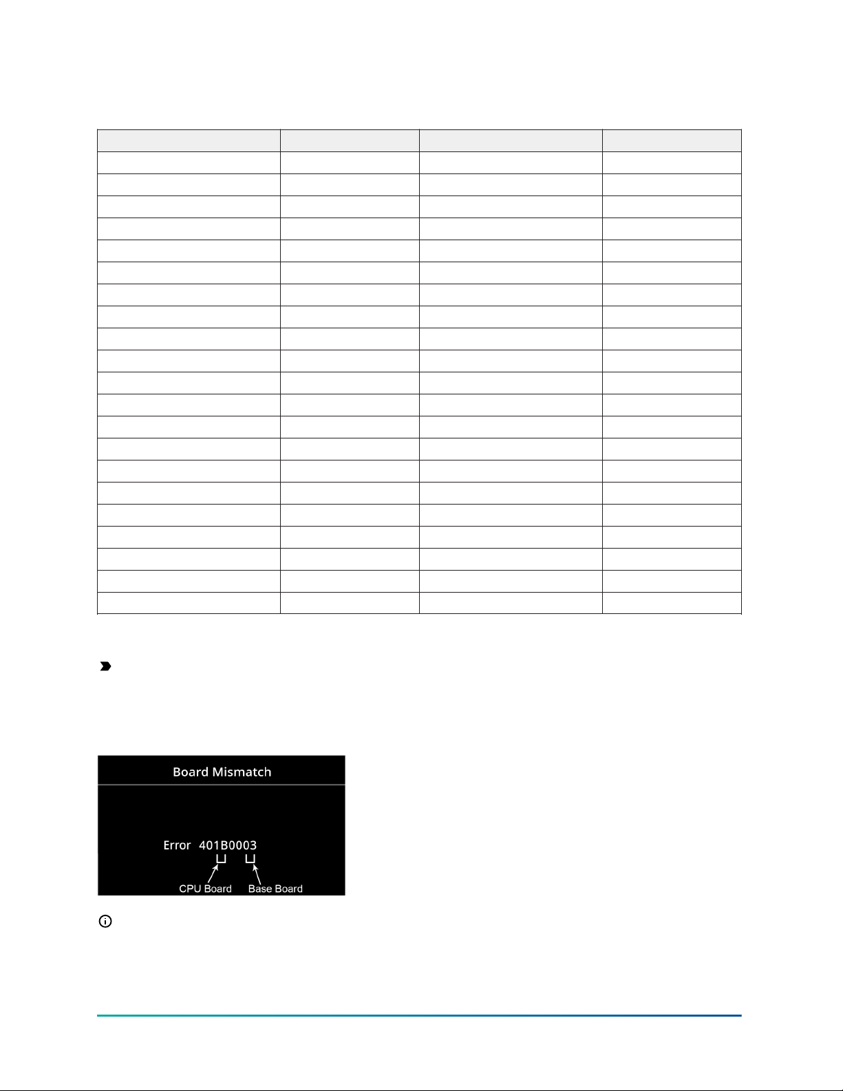
Determining correct pairing of CPU Board and Base Board
Important: Make sure you attach the cover that corresponds to its correct base. The CPU
board number needs to match the Base board number. Otherwise you encounter an operation
error after you reattach a cover and base that do not belong together, as shown in Figure 1.
Figure 1: Error code indicating mismatched boards
Note: The example shown in Figure 1 indicates a TEC3612-16 CPU board that is mounted on
the base of a TEC3312-16.
8
TEC3000 Color Series Field-Selectable BACnet MS/TP or N2 Networked and Wireless Thermostat Controllers
Technical Bulletin
Page 9

Wireless TEC3000 networks
The TEC3000 includes an embedded wireless router and can only be used on a ZFR182x or ZFR183x
Pro Series Wireless Network.
The WRG1830/ZFR183x Pro Series Wireless Field Bus System is similar to the WNC1820/ZFR182x
Series wireless system in many ways. But there are several important differences.
• The wireless networks (PANs) formed by the ZFR183x and ZFR182x systems are not
compatible.
• The ZFR182x Series Routers and TEC3000 are not field upgradeable to be compatible with the
ZFR1830 Series System.
Important: ZFR182x Pro Series Wireless System compatible TEC30xx-1x-000 models and
ZFR183x Pro Series Wireless System compatible TEC31xx-1x-000 models are not compatible
with each other and cannot be used under the same PAN ID (network address).
Table 2: ZFR183x Pro Series indoor transmission ranges
Range type Transmission distance
ZFR to ZFR TEC to ZFR
TEC to TEC
Recommended 250 ft (75 m) 250 ft (75 m) 50 ft (15.2 m)
Maximum, Line of Sight 1000 ft (304.8 m) 1000 ft (304.8 m) 100 ft (30 m)
WRZ to ZFR
In ZFR182x Pro Series networks, place every wireless TEC3000 within 50 ft (15 m) of at least two
other TEC3000 or ZFR182x wireless devices.
In ZFR183x Pro Series networks, place every wireless TEC3000 within 250 ft (76.2 m) of at least two
other ZFR183x Pro Series wireless TEC3000.
If any wireless TEC3000 is not within 50 ft (15 m) of a ZFR182x Pro Series, or 250 ft (76.2) of a
ZFR183x Pro Series system with other compatible wireless TEC, use compatible ZFR182x or ZFR183x
Routers as repeaters with applicable accessories to provide multiple wireless data pathways.
Note: Change the address of the wireless TEC. The address on the wireless TEC is invalid from
the factory so it must be changed when installed.
A wireless network requires a network coordinator/gateway. See the WNC1800/ZFR182x Pro Series
Wireless Field Bus System Technical Bulletin (LIT-12012356) and WRG1830/ZFR183x Pro Series Wireless
Field Bus System Technical Bulletin (LIT-12013553) for more information about the layout of a ZFR182x
or ZFR183x Pro Series Network.
Configuring a wired TEC3000 for MS/TP or N2 bus
The TEC3000 supports network connectivity to a BAS using a BACnet MS/TP or N2 bus. You select
BACnet MS/TP or N2 communication through the software.
Wiring the network
N2 and BACnet MS/TP protocols use the same physical connections for an RS-485 connection, that
requires three conductors:
• NET +
• NET -
Technical Bulletin
9TEC3000 Color Series Field-Selectable BACnet MS/TP or N2 Networked and Wireless Thermostat Controllers
Page 10
• NET COM
Connect the TEC3000 in line with other devices on the network.
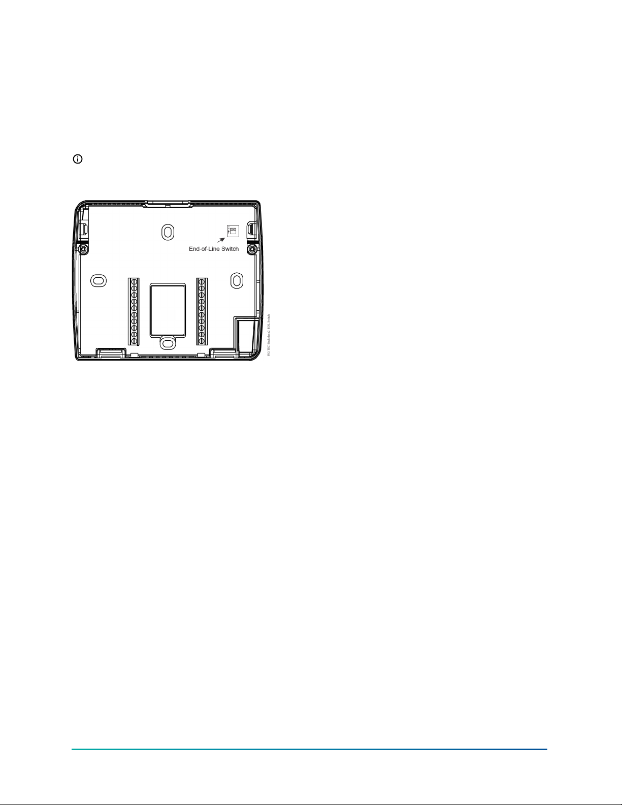
End-of-Line termination
When the TEC3000 is the last device on the bus, make sure the end-of-line (EOL) switch on the I/O
board is in the On position.
Note: If the EOL switch is not on the I/O board, the thermostat is a stand-alone model.
Figure 2: EOL switch positions
Setting the network parameters
All network configuration is done through the software. On the home screen, click the menu icon.
Scroll down to Network Setup for the network settings. Out of the box, the thermostat is configured
in BACnet MS/TP mode. To change to the N2 mode, select FC Comm Mode and change to N2. This
change reboots the device when you click the save icon.
10
TEC3000 Color Series Field-Selectable BACnet MS/TP or N2 Networked and Wireless Thermostat Controllers
Technical Bulletin
Page 11

Table 3: Setup menus
Menu parameter Description
BACnet Instance ID This is the instance ID of the device on the BACnet MS/TP bus. BACnet
MS/TP systems use the instance ID for identification of the device. It can
be set from 1 to 4,194,302 and is unique to that site. The default is 1.
BACnet Device Address This is the physical MAC address of the BACnet MS/TP device on the bus.
It can be set from 4 to 127. Two devices on the same bus cannot have the
same BACnet MS/TP device address. The default is 4.
MSTP Baud Rate This is the baud rate that the TEC communicates on the network. The
default value is Auto, which allows the device to automatically detect
the baud rate of the BACnet MS/TP bus and operate at that speed. An
incorrect value causes the device to not communicate on the network,
and can potentially cause the network to fail. Options for this setting are
Auto, 1,200, 9,600, 19,200, 38,400, and 76,800 Baud.
BACnet Encoding Type This is the method of data encoding and is used by the BACnet MS/TP
bus. The default value, ISO 10646 (UCS-2), is the encoding used by the
Metasys® platform. When operating on a third-party BAS, refer to the
documentation provided with the BAS for the correct encoding type.
N2 Device Address This is the physical MAC address of the N2 device on the bus and can be
set from 1 to 255. Two devices on the same bus cannot have the same N2
device address.
Connecting the MS/TP or N2 bus
About this task: To connect the MS/TP or N2 bus, complete the following steps:
1. Set the MS/TP or N2 address of the TEC3000 Series BACnet MS/TP or N2 Network
Temperature and Humidity Thermostat Controller according to the engineering drawings.
Note: For more details on wiring the MS/TP Communications bus, refer to the MS/TP
Communications Bus Technical Bulletin (LIT-12011034).
2. Observe the polarity when connecting the bus wires to the thermostat controller.
3. After the bus wires are connected to the first thermostat controller, continue in a daisychained fashion to the next thermostat controller.
Note: The bus wiring must be twisted-pair lines. Do not run the bus wiring in the same
conduit as line voltage wiring (30 VAC or above) or other wiring that switches power to
highly inductive loads (such as contactors, coils, motors, or generators).
Result
Configure the thermostat controller for automatic baud rate detection. Do not exceed the
maximum number of devices allowed on a field bus. Ensure that the wiring terminations are set
correctly and that all communication wiring is daisy-chained with no T taps.
Technical Bulletin
11TEC3000 Color Series Field-Selectable BACnet MS/TP or N2 Networked and Wireless Thermostat Controllers
Page 12

MS/TP or N2 thermostat controller mapping
Preparation
About this task: Before you map a TEC3000 Series field-selectable BACnet MS/TP or N2 Network
Thermostat Controller into an NAE:
1. Decide which points within the thermostat controller need to be mapped. Only map the
points that need to be viewed or commanded on a regular basis. Excessive point mapping
lowers system performance. Suggested points for mapping include Zone Temp, System
Mode, Fan Mode, Manual Occupancy Mode, Occupied Heating Setpoint, Occupied Cooling
Setpoint, Unoccupied Heating Setpoint, and Unoccupied Cooling Setpoint. In addition, alarm
points may be mapped if they are used, and other points may be mapped if required. Use the
Engineering view of the MS/TP trunk on the NAE to examine infrequently used points.
Note: Set all thermostat controller configuration parameters as required before you
map the points into the NAE. If you alter any thermostat controller configuration
parameters after you mapped the points into the thermostat controller, re-map all
points individually, because some exposed points might have been added or removed.
Be careful when you map configuration parameters, because they should only be
mapped if the operator is fully familiar with their use.
2. Verify that a Field bus is defined in the NAE. BACnet MS/TP or N2 devices attach to a Field bus.
Refer to the Metasys N2 Communication Bus Technical Bulletin (LIT-636018) for instructions on
how to define a Field bus.
3. For Metasys system software earlier than Release 4.0, verify that a BACnet Integration is
defined for the Field bus. The thermostat controllers are mapped as BACnet MS/TP devices
under a Field bus BACnet Integration. Refer to the BACnet Controller Integration with NAE/
NCE Technical Bulletin (LIT-1201531) or the Metasys N2 Communication Bus Technical Bulletin
(LIT-636018) for instructions on how to define a BACnet Integration.
Note: Metasys system Release 7.0.7 or later software is required for correct support of
text strings on all network points.
Result
At this point, you can map the thermostat controller and the required points inside the thermostat
controller.
Adding a thermostat controller
You must add the thermostat controller before you can map its points. To add the thermostat
controller, select either the Field or N2 bus (depending on the selected configuration) and choose
Field Device from the Insert menu.
Assisted Definition using Auto Discovery is the easiest way to add a new thermostat controller
online; however, this method requires that the thermostat controller that you want to add is
connected and ready to communicate. Device addresses must be unique from 4 to 127 for the
BACnet MS/TP and 1 to 255 for the N2 network.
Note: Do not use the MAP-ALL functionality when you add the thermostat controller to a
Supervisory device, because this adds all TEC3000 Trend Objects which cannot be viewed in
the Supervisory device. These trends update every 15 minutes which could cause issues in the
Supervisory device.
Adding BACnet MS/TP points
You must map the required points under the thermostat controller device. To map the points, select
the thermostat controller device under the BACnet Integration (if required, refresh the tree view to
see a newly added thermostat controller device) and choose Field Point from the Insert menu.
12
TEC3000 Color Series Field-Selectable BACnet MS/TP or N2 Networked and Wireless Thermostat Controllers
Technical Bulletin
Page 13

Assisted Definition using Auto Discovery is the easiest way to add new points online; however, this
function requires that the thermostat controller that you want to map is connected and ready to
communicate. When mapping points offline, the point type must match the BACnet object type
(for example, AV, MV, BI), and the point instance number must match the point BACnet instance
number.
Adding N2 points
You must map the required points under the thermostat controller device. To map the points, select
the thermostat controller device under the N2 Integration (if required, refresh the tree view to see a
newly added thermostat controller device) and choose Field Point from the Insert menu.
Then you need to add the appropriate PRN file based on the TEC model being used as an extension
to the device. Multi-state points are defined as ADI points in the PRN file. You must map these using
either MI or MO NAE object types. Following the field point addition, object units may need further
tailoring of units and enum set values. See Table 4, Table 5 or Table 6 for the enum set values.
MS/TP or N2 bus points tables
Thermostat controllers
Table 4: Points for TEC3612-1x-000, TEC3613-1x-000, TEC3012-1x-000, TEC3013-1x-000,
TEC3112-14-000, and TEC3113-14-000
Point description Point name Object
type
Control Mode SYSTEM-MODE MV 29500 MI, ADI 1 TEC3000 Unit Control Mode
Unit Enable UNITEN-MODE MV 29501 MI, ADI 2 Shutdown/Enable
Occupied Cooling
Setpoint
Occupied Heating
Setpoint
Unoccupied
Cooling Setpoint
Unoccupied
Heating Setpoint
Standby Cooling
Setpoint
Standby Heating
Setpoint
Setpoint Offset WC-ADJ AV 29508 AO, ADF 7 (Negative) Max Setpoint Offset.
Hold/Run HOLDRUN-
Humidity Setpoint ZNH-SP AV 29510 AO, ADF 8 0% RH to 100% RH
CLGOCC-SP AV 29502 AO, ADF 1 60°F to 100°F (15.05°C to 37.78°C)
HTGOCC-SP AV 29503 AO, ADF 2 45°F to 85°F (7.22°C to 29.44°C)
CLGUNOCC-SP AV 29504 AO, ADF 3 60°F to 100°F (15°C to 38°C)
HTGUNOCC-SP AV 29505 AO, ADF 4 45°F to 85°F (7°C to 30°C)
CLGSTBY-SP AV 29506 AO, ADF 5 60°F to 100°F (15°C to 38°C)
HTGSTBY-SP AV 29507 AO, ADF 6 45°F to 85°F (7°C to 30°C)
MV 29509 MI, ADI 3 Hold/Run
MODE
InstanceIDPoint
type
Point
address
Unit (IP), enum set/range
1. Auto
2. Cooling
3. Heating
1. Shutdown
2. Enable
*When Occ Setpoint Select = Setpoint
Offset. Otherwise, see Table 11 for
constraints
1. Hold
2. Run
Technical Bulletin
13TEC3000 Color Series Field-Selectable BACnet MS/TP or N2 Networked and Wireless Thermostat Controllers
Page 14

Table 4: Points for TEC3612-1x-000, TEC3613-1x-000, TEC3012-1x-000, TEC3013-1x-000,
TEC3112-14-000, and TEC3113-14-000
Point description Point name Object
type
Network Override
NET-OAT AV 29513 AO, ADF 11 -50°F to 125°F (-46°C to 52°C)
Outdoor Air
Temperature
Network Override
NET-OAH AV 29514 AO, ADF 12 0% RH to 100% RH
Outdoor Air
Humidity
Network Override
NET-SAT AV 29515 AO, ADF 13 0°F to 150°F (-18°C to 65°C)
Supply Air
Temperature
Network Override
NET-ZNH AV 29516 AO, ADF 14 0% RH to 100% RH
Zone Humidity
Reset PID Tuning TUNING-RESET MV 29517 MI, ADI 4 No/Yes
Manual Occupancy
OCCOVRD-MODE MV 29518 MI, ADI 5 UI Occ Override
Mode
Supervisor
NET-OCC MV 29519 MI, ADI 6 Occ Schedule
Occupancy
Occupancy
OCC-CONFIG MV 29520 MI, ADI 7 SE Occupancy Mode
Schedule Source
Changeover Mode CGOVR-MODE MV 29523 MI, ADI 8 TEC3000 Unit Control Mode
Passcode
PASSCODE
11
MV 29522 AI, ADF 15 00000 to 99999
Fan Mode FAN-MODE MV 29524 MI, ADI 9 TEC3000 Fan Mode
Fan Override FANOVRD-MODE MV 29525 MI, ADI 10 UI Fan Override
InstanceIDPoint
type
Point
address
Unit (IP), enum set/range
1. No
2. Yes
1. No Override
2. Occupied
3. Unoccupied
1. Occupied
2. Unoccupied
3. Standby
1. Schedule
2. External
1. Auto
2. Cooling
3. Heating
1. On
2. Auto
3. Smart
*This point only shows if the unit type
is 2-pipe or 4-pipe and the fan type is
single- or variable-speed
1. On
2. Auto
3. Quiet
*This point only shows if the unit type
is 2-pipe or 4-pipe and the fan type is
single- or variable-speed
14
TEC3000 Color Series Field-Selectable BACnet MS/TP or N2 Networked and Wireless Thermostat Controllers
Technical Bulletin
Page 15

Table 4: Points for TEC3612-1x-000, TEC3613-1x-000, TEC3012-1x-000, TEC3013-1x-000,
TEC3112-14-000, and TEC3113-14-000
Point description Point name Object
type
Aux Mode AUX-MODE MV 29527 MI, ADI 11 TEC3000 Aux Mode
Units TEMP-UNITS MV 29528 MI, ADI 12 Unit Set
Max Setpoint Offset MAXSP-OFFSET AV 29529 AO, ADF 29 0 to 20 delta °F (0 to 11 delta °C)
Changeover
Setpoint
Unit Status UNIT-S MV 29700 MI, ADI 13 TEC3000 Detailed Control Status2
Operational Space
Temperature
Return Air Humidity EFF-ZNH AV 29702 AO, ADF 17 n/a
Supply Air
Temperature
CGOVR-SP AV 29530 n/a n/a 40°F to 200°F (4°C to 93°C)
EFF-ZNT AV 29701 AO, ADF 16 n/a
EFF-SAT AV 29703 AO, ADF 18 n/a
InstanceIDPoint
type
Point
address
Unit (IP), enum set/range
1. Not Used
2. Occupied NO
3. Occupied NC
4. Occupied Fan NO
5. Occupied FAN NC
6. On
7. Off
1. IP
2. SI
1. System Fault
2. Airflow Fault
3. Open Window
4. Control Off
5. Unreliable Temperature
6. Dehumidification
7. Idle
8. Cooling
9. Heating
10. Cooling Unavailable
11. Heating Unavailable
12. Cooling Unavailable due to
Changeover
13. Cooling Unavailable due to OA
Temp
14. Cooling Unavailable due to Control
Mode
15. Heating Unavailable due to
Changeover
16. Heating Unavailable due to OA
Temp
17. Heating Unavailable due to Control
Mode
18. Load Shed Active
19. Dehumidifying – Reheat
20. Dehumidifying – Fan Only
21. Dehum Unavail By Dew Point
Technical Bulletin
15TEC3000 Color Series Field-Selectable BACnet MS/TP or N2 Networked and Wireless Thermostat Controllers
Page 16

Table 4: Points for TEC3612-1x-000, TEC3613-1x-000, TEC3012-1x-000, TEC3013-1x-000,
TEC3112-14-000, and TEC3113-14-000
Point description Point name Object
type
Operational
Outdoor Air
Temperature
Active Setpoint EFF-SETPOINT AV 29705 AO, ADF 20 n/a
CV Operating
Cooling Setpoint
CV Operating
Heating Setpoint
Occupancy Status EFF-OCC MV 29708 MI, ADI 14 TEC3000 Occupancy Status
Occupancy Input
Source
Changeover State CGOVR-S n/a n/a MA, ADI 16 TEC3000 Changeover Status
Fan % Command FANSPD-% AV 29711 AO, ADF 23 0% to 100%
Fan Speed FANSPD-S MV 29712 MI, ADI 18 Supply Fan Status
Cool/Dehum PID
Control
Heat PID Cmd HTGPID-% AV 29717 AO, ADF 26 0% to 100%
Reheat PID Cmd RHPID-% AV 29720 AO, ADF 27 0% to 100%
Load Shed Active LOADSHED-EN MV 29728 MI, ADI 19 No/Yes
Load Shed Rate
Limit
Load Shed Adjust LOADSHED-RL-
Occupancy
Override Duration
EFF-OAT AV 29704 AO, ADF 19 n/a
EFFCLG-SP AV 29706 AO, ADF 21 n/a
EFFHTG-SP AV 29707 AO, ADF 22 n/a
OCCSOURCE-S MV 29709 MI, ADI 15 TEC3000 Occupancy Source
CLGPID-% AV 29714 AO, ADF 25 0% to 100%
LOADSHED-RL AV 29725 AO, ADF 30 0°F to 1°F/min (0°C to 0.5°C/min)
AV 29726 AO, ADF 31 0 to 8 delta °F (0 to 5 delta °C)
ADJ
TEMPOCC-LEN AV 29727 AO, ADF 32 0 minutes to 300 minutes
InstanceIDPoint
type
Point
address
Unit (IP), enum set/range
1. Occupied
2. Temp Occupancy
3. Unoccupied
4. Standby
5. Occupied-Override
6. Unoccupied-Override
1. Occupancy BI
2. Temp Occ BI
3. Temp Occ
4. Occ Override
5. Local Schedule
6. BAS Schedule
7. Occupancy Sensor
1. Changeover Disabled
2. Cooling Mode
3. Heating Mode
4. Supply Temperature Unreliable
1. Off
2. On
3. Low
4. Medium
5. High
1. No
2. Yes
16
TEC3000 Color Series Field-Selectable BACnet MS/TP or N2 Networked and Wireless Thermostat Controllers
Technical Bulletin
Page 17

Table 4: Points for TEC3612-1x-000, TEC3613-1x-000, TEC3012-1x-000, TEC3013-1x-000,
TEC3112-14-000, and TEC3113-14-000
Point description Point name Object
type
Lockout Level LOCL-LVL MV 29531 MI-ADI 20 States (0-2)
Unoccupied Off
UNOCC-OFF-DLY AV 29532 AO, ADF 33 0 minutes to 10 minutes
Delay
Heat Prop Band HTG-PROP-BAND AV 29535 AO, ADF 34 5 to 30 delta °F (2.8 to 16.7 delta °C)
Heat Integral Time HTG-INT-TIME AV 29536 AO, ADF 35 300 seconds to 1600 seconds
Heat Process Range HTG-PROC-
AV 29537 AO, ADF 36 10 to 100 delta °F (5.6 to 56 delta °C)
RANGE
Heat Saturation
HTG-SAT-TIME AV 29538 AO, ADF 37 60 seconds to 900 seconds
Time
Heat Time Constant HTG-TIME-
AV 29539 AO, ADF 38 360 seconds to 1440 seconds
CONST
Heat Process Dead
HTG-DEAD-TIME AV 29540 AO, ADF 39 20 seconds to 120 seconds
Time
Heat Period HTG-PERIOD AV 29541 AO, ADF 40 30 seconds to 120 seconds
Cool Prop Band CLG-PROP-BAND AV 29542 AO, ADF 41 5 to 30 delta °F (2.8 to 16.7 delta °C)
Cool Integral Time CLG-INT-TIME AV 29543 AO, ADF 42 300 seconds to 1600 seconds
Cool Process Range CLG-PROC-
AV 29544 AO, ADF 43 10 to 100 delta °F (5.6 to 56 delta °C)
RANGE
Cool Saturation
CLG-SAT-TIME AV 29545 AO, ADF 44 60 seconds to 900 seconds
Time
Cool Time Constant CLG-TIME-CONST AV 29546 AO, ADF 45 360 seconds to 1440 seconds
Cool Process Dead
CLG-DEAD-TIME AV 29547 AO, ADF 46 20 seconds to 120 seconds
Time
Cool Period CLG-PERIOD AV 29548 AO, ADF 47 30 seconds to 120 seconds
Deadband DEADBAND AV 29556 AO, ADF 55 1.4 to 3 delta °F (0.78 to 1.66 delta °C)
Min Heating
MINHTG-SP AV 29559 AO, ADF 56
Setpoint
Max Heating
MAXHTG-SP AV 29560 AO, ADF 57 Present value of Min Heating Setpoint
Setpoint
Min Cooling
MINCLG-SP AV 29561 AO, ADF 58 Present value of Max Heating Setpoint
Setpoint
Max Cooling
MAXCLG-SP AV 29562 AO, ADF 59 Min Cooling Setpoint present to 100°F
Setpoint
Occ Setpoint Select OCCSP-SEL MV 29563 AO, ADF 60 Occ Setpoint Select
Min Setpoint MIN-SP AV 29564 AO, ADF 61
Max Setpoint MAX-SP AV 29565 AO, ADF 62
Heat Cool Setpoint
Mode
HTGCLGSPMODE
MV 29566 MI, ADI 24 Heat Cool Setpoint Mode
Common Setpoint COMMON-SP AV 29567 AO, ADF 62 55°F to 90°F (12.77°C to 32.22°C)
InstanceIDPoint
type
Point
address
Unit (IP), enum set/range
1. State 0
2. State 1
3. State 2
2
45°F (7.22°C) to Max Heating Setpoint
Present Value
2
(MINHTG-SP) to present value of Min
Cooling Setpoint (MINCLG-SP)minus 1
(MAXHTG-SP) plus 1 to present value of
Max Cooling Setpoint (MAXCLG-SP)
(37.78°C)
2
1. Setpoint Offset
2. Min and Max Setpoint
3
45°F to 85°F (7°C to 30°C)
60°F to 100°F (16°C to 38°C)
3
3
1. Common Setpoint
2. Individual Setpoints
2
2
Technical Bulletin
17TEC3000 Color Series Field-Selectable BACnet MS/TP or N2 Networked and Wireless Thermostat Controllers
Page 18

Table 4: Points for TEC3612-1x-000, TEC3613-1x-000, TEC3012-1x-000, TEC3013-1x-000,
TEC3112-14-000, and TEC3113-14-000
Point description Point name Object
type
Fan Mode 2 FAN-MODE2 MV 29568 MI, ADI 27 TEC3000 Fan Mode 2
Fan Override 2 FAN-OVRD2 MV 29569 MI, ADI 28 UI Fan Override 2
Temp Control Setup TEMPCTRL-
SETUP
Control State TEMPCTRL-
SETUP2
Network Override
Zone Temperature
Signal Strength Signal Strength MV 29724 n/a n/a Wireless Signal Strength
PAO1 Output /
Cooling Valve %
Command
PAO2 Output /
Heating Valve %
Command
AO1 Output / Fan
Speed Percent
Command
NET-ZNT AV 29571 AO, ADF 63 -50°F to 120°F (-45°C to 49°C)
CLG-O AO 86914 AO, AO 1 0% to 100%
HTG-O AO 86915 AO, AO 2 0% to 100%
VSF-O AO 86905 AO, AO 3 0% to 100%
MV 29533 MI, ADI 21 TEMP_CONTROL_SETUP
MV 29570 MI, ADI 26 TEMP_CONTROL_SETUP_SUBSET
InstanceIDPoint
type
Point
address
Unit (IP), enum set/range
1. Auto
2. Smart
3. Low
4. Medium
5. High
*This point only shows if the unit type
is 2-pipe or 4-pipe and the fan type is
multispeed
1. Auto
2. Quiet
3. Low
4. Medium
5. High
*This point only shows if the unit type
is 2-pipe or 4-pipe and the fan type is
multispeed
1. Automatic PID Tuning
2. Deadband Override
3. Manual PID Tuning
4. On Off Control (available on units
with single-speed fan and On/Off
actuators configured)
1. Automatic PID Tuning
2. Deadband Override
3. Manual PID Tuning (available on
units with a multi-speed, variable
speed fan, or floating actuators
configured)
1. None
2. Weak
3. Average
4. Strong
18
TEC3000 Color Series Field-Selectable BACnet MS/TP or N2 Networked and Wireless Thermostat Controllers
Technical Bulletin
Page 19

Table 4: Points for TEC3612-1x-000, TEC3613-1x-000, TEC3012-1x-000, TEC3013-1x-000,
TEC3112-14-000, and TEC3113-14-000
Point description Point name Object
4
BO1 Command /
CLGO-C BO 86908 BO, BO 1 Inactive/Active
type
BO1 Cool NO/
4
Open
BO2 Command /
FANL-C BO 86909 BO, BO 2 Inactive/Active
BO2 Fan Low
Command
BO3 Command /
FANM-C BO 86910 BO, BO 3 Inactive/Active
BO3 Fan Medium
Command
BO4 Command /
FANH-C BO 86911 BO, BO 4 Inactive/Active
BO4 Fan High
Command
BO5 Command /
HTGO-C BO 86912 BO, BO 5 Inactive/Active
BO5 Heat NO/
4
Open
5
BO6 Command /
BO6 Cool NC/Close
BO7 Command /
CLGC-C BO 87101 BO, BO 6 Inactive/Active
5
HTGC-C BO 87102 BO, BO 7 Inactive/Active
BO7 Heat NC/
5
Close
AUX Command /
AUX BO 86913 BO, BO 8 Inactive/Active
BO8 AUX
BI1 Sensor / Binary
BI1-S BI 30827 BI, BI 1 Inactive/Active
Input 1
BI2 Sensor / Binary
BI2-S BI 30828 BI, BI 2 Inactive/Active
Input 2
Schedule Schedule Schedule 10133 n/a n/a n/a
Local Occupancy LOCAL-OCC MV 6 n/a n/a Occ Schedule
Calendar Calendar Calendar 10019 n/a n/a n/a
Dehumidification
DEHUM ENABLE MV 29736 n/a n/a No/Yes
Enable
Unocc Dehum
Enable
UNOCC DEHUM
ENABLE
MV 29737 n/a n/a No/Yes
InstanceIDPoint
type
Point
address
Unit (IP), enum set/range
1. Inactive
2. Active
1. Inactive
2. Active
1. Inactive
2. Active
1. Inactive
2. Active
1. Inactive
2. Active
1. Inactive
2. Active
1. Inactive
2. Active
1. Inactive
2. Active
1. Inactive
2. Active
1. Inactive
2. Active
1. Occupied
2. Unoccupied
3. Standby
4. Not Set
1. No
2. Yes
1. No
2. Yes
Technical Bulletin
19TEC3000 Color Series Field-Selectable BACnet MS/TP or N2 Networked and Wireless Thermostat Controllers
Page 20

Table 4: Points for TEC3612-1x-000, TEC3613-1x-000, TEC3012-1x-000, TEC3013-1x-000,
TEC3112-14-000, and TEC3113-14-000
Point description Point name Object
type
Chilled
Water Supply
Temperature
Chilled
Water Supply
Temperature
Setpoint
Network
Override Chilled
Water Supply
Temperature
Outdoor Air
Humidity
Cooling Valve
Minimum Position
Cooling Valve
Starting Position
Heating Valve
Starting Position
Coil Tempering
Time
Dehumidification
Overcool Limit
Dehumidification
Sequence Mode
Dehumidification
Sequence Mode
EFF-CHWST AV 29734 n/a n/a n/a
CHWST-SP AV 29735 n/a n/a 0 to 250 deg F (-17 to 121 deg C)
NET-CHWST AV 29736 n/a n/a 0 to 250 deg F (-17 to 121 deg C)
EFF-OAH AV 29737 n/a n/a n/a
CLVVLV-MIN-POS AV 29738 n/a n/a 50% to 75%
CLGVLV-STARTPOS
HTGVLV-STARTPOS
COIL-TPR-TIME AV 29741 n/a n/a 3 minutes to 10 minutes
DEHUMOVRCLG-LIM
4PIPE-DEHUMSEQ-MODE
2PIPE-DEHUMSEQ-MODE
AV 29739 n/a n/a 50% to 100%
AV 29740 n/a n/a 50% to 100%
AV 29742 n/a n/a 1 to 5 delta deg F, delta deg C
MV 29729 n/a n/a TEC3000 FCU Dehum Seq Mode
MV 29730 n/a n/a TEC3000 Dehum Sequence
InstanceIDPoint
type
Point
address
Unit (IP), enum set/range
*This point only shows if there is neither
a CHWST sensor wired to TEC nor a
Network override value setup and
Dehum Enable is set to Enable
*This point only shows if
Dehumidification Sequence Mode is
setup as Individual Coils or 2-pipe with
reheat and Dehum Enable is set to
Enable
*This point only shows if
Dehumidification Sequence Mode is
setup as Individual Coils or 2-pipe with
reheat and Dehum Enable is set to
Enable
*This point only shows if
Dehumidification Sequence Mode is
setup as Individual Coils and Dehum
Enable is set to Enable
*This point only shows if
Dehumidification Sequence Mode is
setup as Single Coil and Dehum Enable is
set to Enable
*This point only shows if
Dehumidification Sequence Mode is
setup as Single Coil and Dehum Enable is
set to Enable
1. Individual Coils
2. Single Coil
*This point only shows if Unit Type
is 4-pipe and Dehum Enable is set to
Enable
1. Individual Coils
2. Single Coil
3. 2-Pipe With Reheat
*This point only shows if Unit Type
is 2-pipe and Dehum Enable is set to
Enable
20
TEC3000 Color Series Field-Selectable BACnet MS/TP or N2 Networked and Wireless Thermostat Controllers
Technical Bulletin
Page 21

Table 4: Points for TEC3612-1x-000, TEC3613-1x-000, TEC3012-1x-000, TEC3013-1x-000,
TEC3112-14-000, and TEC3113-14-000
Point description Point name Object
type
Scheduled
Circulation Enable
Scheduled
Circulation Only
When Occupied
Minimum Hourly
Fan Runtime
Variable Speed Fan
Circulation Setpoint
Multi Speed Fan
Circulation Setpoint
Medium Fan On
Diff Sp
Medium Fan Off
Diff Sp
High Fan On Diff Sp HIGH-FAN-ON-SP AV 29902 n/a n/a 1 to 3 delta deg F (0.55 to 1.67 delta deg
High Fan Off Diff Sp HIGH-FAN-OFF-SPAV 29903 n/a n/a 0.5 to 2 delta deg F (0.28 to 1.1 delta deg
1 The passcode cannot be changed from BAS. The passcode can only be defined by the local display or through Mobile
Access Portal (MAP) version 4.0.
2 The Occ Setpoint Select is set to the Min and Max Setpoint and Heat Cool Setpoint Mode is set to the Individual Setpoint.
3 The Occ Setpoint Select is set to the Min and Max Setpoint and Heat Cool Setpoint Mode is set to the Common Setpoint.
4 This is the output used when wired to the Normally Open (N.O.) terminal.
5 This is the output used when wired to the Normally Closed (N.C.) terminal.
SCH-CIR-EN MV 29731 n/a n/a Disable/Enable
SCH-CIR-ONLYOCC
MIN-HR-FAN AV 29743 n/a n/a 5 minutes to 30 minutes
VAR-FAN-CIR-SP AV 29744 n/a n/a 0% to 100%
MULTI-FAN-CIR-SPMV 29733 n/a n/a Sensitivity
MED-FAN-ON-SP AV 29900 n/a n/a 1 to 2 delta deg F (0.55 to 1.1 delta deg C)
MED-FAN-OFF-SP AV 29901 n/a n/a 0 to 1 delta deg F (0 to 0.55 delta deg C)
MV 29732 n/a n/a Disable/Enable
InstanceIDPoint
type
Point
address
Unit (IP), enum set/range
1. Disable
2. Enable
1. Disable
2. Enable
*This point shows Unreliable if
Scheduled Circulation Enable is set to
Disable
*This point shows Unreliable if
Scheduled Circulation Enable is set to
Disable
*This point only shows if Fan Type is
Variable Speed and Scheduled Circulation
Enable is True
1. Low
2. Medium
3. High
*This point only shows if Fan Type is
Multi Speed and Scheduled Circulation
Enable is True
*This point only shows when Fan Type is
Multi Speed and Temp Control Setup is
On Off Control
*This point only shows when Fan Type is
Multi Speed and Temp Control Setup is
On Off Control
C)
*This point only shows when Fan Type is
Multi Speed and Temp Control Setup is
On Off Control
C)
*This point only shows when Fan Type is
Multi Speed and Temp Control Setup is
On Off Control
Technical Bulletin
21TEC3000 Color Series Field-Selectable BACnet MS/TP or N2 Networked and Wireless Thermostat Controllers
Page 22

Table 5: Points for TEC3622-1x-000, TEC3623-1x-000, TEC3022-1x-000, TEC3023-1x-000,
TEC3122-14-000, and TEC3123-14-000
Point description Point name Object
type
Control Mode SYSTEM-MODE MV 29500 MI, ADI 1 TEC3000 Unit Control Mode
Unit Enable UNITEN-MODE MV 29501 MI, ADI 2 Shutdown/Enable
Occupied Cooling
Setpoint
Occupied Heating
Setpoint
Unoccupied Cooling
Setpoint
Unoccupied
Heating Setpoint
Standby Cooling
Setpoint
Standby Heating
Setpoint
Setpoint Offset WC-ADJ AV 29508 AO, ADF 7 (Negative) Max Setpoint Offset.
Hold/Run HOLDRUN-
Humidity Setpoint ZNH-SP AV 29510 AO, ADF 8 0% RH to 100% RH
Network Override
Outdoor Air
Temperature
Network Override
Outdoor Air
Humidity
Network Override
Supply Air
Temperature
Network Override
Zone Humidity
Reset PID Tuning TUNING-RESET MV 29517 MI, ADI 4 No/Yes
Manual Occupancy
Mode
Supervisory
Occupancy
CLGOCC-SP AV 29502 AO, ADF 1 60°F to 100°F (15.05°C to 37.78°C)
HTGOCC-SP AV 29503 AO, ADF 2 45°F to 85°F (7.22°C to 29.44°C)
CLGUNOCC-SP AV 29504 AO, ADF 3 60°F to 100°F (15°C to 38°C)
HTGUNOCC-SP AV 29505 AO, ADF 4 45°F to 85°F (7°C to 30°C)
CLGSTBY-SP AV 29506 AO, ADF 5 60°F to 100°F (15°C to 38°C)
HTGSTBY-SP AV 29507 AO, ADF 6 45°F to 85°F (7°C to 30°C)
MV 29509 MI, ADI 3 Hold/Run
MODE
NET-OAT AV 29513 AO, ADF 11 -50°F to 125 °F (-46°C to 52 °C)
NET-OAH AV 29514 AO, ADF 12 0% RH to 100% RH
NET-SAT AV 29515 AO, ADF 13 0°F to 150°F (-18°C to 65°C)
NET-ZNH AV 29516 AO, ADF 14 0% RH to 100% RH
OCCOVRDMODE
NET-OCC MV 29519 MI, ADI 6 Occ Schedule
MV 29518 MI, ADI 5 UI Occ Override
InstanceIDPoint
type
Point
address
Unit (IP), enum set/range
1. Auto
2. Cooling
3. Heating
1. Shutdown
2. Enable
*When Occ Setpoint Select = Setpoint
Offset. Otherwise, see Table 11 for
constraints
1. Hold
2. Run
1. No
2. Yes
1. No Override
2. Occupied
3. Unoccupied
1. Occupied
2. Unoccupied
3. Standby
22
TEC3000 Color Series Field-Selectable BACnet MS/TP or N2 Networked and Wireless Thermostat Controllers
Technical Bulletin
Page 23

Table 5: Points for TEC3622-1x-000, TEC3623-1x-000, TEC3022-1x-000, TEC3023-1x-000,
TEC3122-14-000, and TEC3123-14-000
Point description Point name Object
type
Occupancy
OCC-CONFIG MV 29520 MI, ADI 7 SE Occupancy Mode
Schedule Source
Changeover Mode CGOVR-MODE MV 29523 MI, ADI 8 TEC3000 Unit Control Mode
Passcode
1
PASSCODE
1
MV 29522 AI, ADF 15 00000 to 99999
Fan Mode FAN-MODE MV 29524 MI, ADI 9 TEC3000 Fan Mode
Fan Override FANOVRD-
MV 29525 MI, ADI 10 UI Fan Override
MODE
Aux Mode AUX-MODE MV 29527 MI, ADI 11 TEC3000 Aux Mode
Units TEMP-UNITS MV 29528 MI, ADI 12 Unit Set
Max Setpoint Offset MAXSP-OFFSET AV 29529 AO, ADF 29 0 to 20 delta °F (0 to 11 delta °C)
Changeover
CGOVR-SP AV 29530 n/a n/a 40°F to 200°F (4°C to 93°C)
Setpoint
InstanceIDPoint
type
Point
address
Unit (IP), enum set/range
1. Schedule
2. External
1. Auto
2. Cooling
3. Heating
1. On
2. Auto
3. Smart
*This point only shows if the unit type
is 2-pipe or 4-pipe and the fan type is
single- or variable-speed
1. On
2. Auto
3. Quiet
*This point only shows if the unit type
is 2-pipe or 4-pipe and the fan type is
single- or variable-speed
1. Not Used
2. Occupied NO
3. Occupied NC
4. Occupied Fan NO
5. Occupied Fan NC
6. On
7. Off
1. IP
2. 2 -SI
Technical Bulletin
23TEC3000 Color Series Field-Selectable BACnet MS/TP or N2 Networked and Wireless Thermostat Controllers
Page 24

Table 5: Points for TEC3622-1x-000, TEC3623-1x-000, TEC3022-1x-000, TEC3023-1x-000,
TEC3122-14-000, and TEC3123-14-000
Point description Point name Object
type
Unit Status UNIT-S MV 29700 MI, ADI 13 TEC3000 Detailed Control Status2
Operational Space
Temperature
Return Air Humidity EFF-ZNH AV 29702 AO, ADF 17 n/a
Supply Air
Temperature
Operational
Outdoor Air
Temperature
Active Setpoint EFF-SETPOINT AV 29705 AO, ADF 20 n/a
CV Operating
Cooling Setpoint
CV Operating
Heating Setpoint
Occupancy Status EFF-OCC MV 29708 MI, ADI 14 TEC3000 Occupancy Status
EFF-ZNT AV 29701 AO, ADF 16 n/a
EFF-SAT AV 29703 AO, ADF 18 n/a
EFF-OAT AV 29704 AO, ADF 19 n/a
EFFCLG-SP AV 29706 AO, ADF 21 n/a
EFFHTG-SP AV 29707 AO, ADF 22 n/a
InstanceIDPoint
type
Point
address
Unit (IP), enum set/range
1. System Fault
2. Airflow Fault
3. Open Window
4. Control Off
5. Unreliable Temperature
6. Dehumidification
7. Idle
8. Cooling
9. Heating
10. Cooling Unavailable
11. Heating Unavailable
12. Cooling Unavailable due to
Changeover
13. Cooling Unavailable due to OA
Temp
14. Cooling Unavailable due to Control
Mode
15. Heating Unavailable due to
Changeover
16. Heating Unavailable due to OA
Temp
17. Heating Unavailable due to Control
Mode
18. Load Shed Active
19. Dehumidifying – Reheat
20. Dehumidifying – Fan Only
21. Dehum Unavail By Dew Point
1. Occupied
2. Temp Occupancy
3. Unoccupied
4. Standby
5. Occupied-Override
6. Unoccupied-Override
24
TEC3000 Color Series Field-Selectable BACnet MS/TP or N2 Networked and Wireless Thermostat Controllers
Technical Bulletin
Page 25

Table 5: Points for TEC3622-1x-000, TEC3623-1x-000, TEC3022-1x-000, TEC3023-1x-000,
TEC3122-14-000, and TEC3123-14-000
Point description Point name Object
type
Occupancy Input
Source
Fan % Command FANSPD-% AV 29711 AO, ADF 23 0% to 100%
Fan Speed FANSPD-S MV 29712 MI, ADI 18 Supply Fan Status
Cool/Dehum PID
Cmd
Heat PID Cmd HTGPID-% AV 29717 AO, ADF 26 0% to 100%
Reheat PID Cmd RHPID-% AV 29720 AO, ADF 27 0% to 100%
Load Shed Active LOADSHED-EN MV 29728 MI, ADI 19 No/Yes
Load Shed Rate
Limit
Load Shed Adjust LOADSHED-ADJ AV 29726 AO, ADF 31 0 to 8 delta °F (0 to 5 delta °C)
Occupancy
Override Duration
Lockout Level LOCK-LVL MV 29531 MI, ADI 20 States (0 to 2)
Unoccupied Off
Delay
Heat Prop Band HTG-PROP-
Heat Integral Time HTG-INT-TIME AV 29536 AO, ADF 35 300 seconds to 1,600 seconds
Heat Process Range HTG-PROC-
Heat Saturation
Time
Heat Time Constant HTG-TIME-
Heat Process Dead
Time
Heat Period HTG-PERIOD AV 29541 AO, ADF 40 30 seconds to 120 seconds
Cool Prop Band CLG-PROP-
Cool Integral Time CLG-INT-TIME AV 29543 AO, ADF 42 300 seconds to 1,600 seconds
OCCSOURCE-S MV 29709 MI, ADI 15 TEC3000 Occupancy Source
CLGPID-% AV 29714 AO, ADF 25 0% to 100%
LOADSHED-RL AV 29725 AO, ADF 30 0°F to 1°F/min (0°C to 0.5°C/min)
TEMPOCC-LEN AV 29727 AO, ADF 32 0 minutes to 300 minutes
UNOCC-OFF-DLY AV 29532 AO, ADF 33 0 minutes to 10 minutes
AV 29535 AO, ADF 34 5 to 30 delta °F (2.8 to 16.7 delta °C)
BAND
AV 29537 AO, ADF 36 10 to 100 delta °F (5.6 to 56 delta °C)
RANGE
HTG-SAT-TIME AV 29538 AO, ADF 37 60 seconds to 900 seconds
AV 29539 AO, ADF 38 360 seconds to 1,440 seconds
CONST
HTG-DEAD-TIME AV 29540 AO, ADF 39 20 seconds to 120 seconds
AV 29542 AO, ADF 41 5 to 30 delta °F (2.8 to 16.7 delta °C)
BAND
InstanceIDPoint
type
Point
address
Unit (IP), enum set/range
1. Occupancy BI
2. Temp Occ BI
3. Temp Occ
4. Occ Override
5. Local Schedule
6. BAS Schedule
7. Occupancy Sensor
1. Off
2. On
3. Low
4. Medium
5. High
1. No
2. Yes
1. State 0
2. State 1
3. State 2
Technical Bulletin
25TEC3000 Color Series Field-Selectable BACnet MS/TP or N2 Networked and Wireless Thermostat Controllers
Page 26

Table 5: Points for TEC3622-1x-000, TEC3623-1x-000, TEC3022-1x-000, TEC3023-1x-000,
TEC3122-14-000, and TEC3123-14-000
Point description Point name Object
type
Cool Process Range CLG-PROC-
AV 29544 AO, ADF 43 10 to 100 delta °F (5.6 to 56 delta °C)
RANGE
Cool Saturation
CLG-SAT-TIME AV 29545 AO, ADF 44 60 seconds to 900 seconds
Time
Cool Time Constant CLG-TIME-
AV 29546 AO, ADF 45 360 seconds to 1,440 seconds
CONST
Cool Process Dead
CLG-DEAD-TIME AV 29547 AO, ADF 46 20 seconds to 120 seconds
Time
Cool Period CLG-PERIOD AV 29548 AO, ADF 47 30 seconds to 120 seconds
Deadband DEADBAND AV 29556 AO, ADF 55 1.4 to 3 delta °F (0.78 to 1.66 delta °C)
Min Heating
MINHTG-SP AV 29559 AO, ADF 56
Setpoint
Max Heating
MAXHTG-SP AV 29560 AO, ADF 57 Present value of Min Heating Setpoint
Setpoint
Min Cooling
MINCLG-SP AV 29561 AO, ADF 58 Present value of Max Heating Setpoint
Setpoint
Max Cooling
MAXCLG-SP AV 29562 AO, ADF 59 Min Cooling Setpoint present to 100°F
Setpoint
Occ Setpoint Select OCCSP-SEL MV 29563 AO, ADF 60 Occ Setpoint select
Min Setpoint MIN-SP AV 29564 AO, ADF 61
Max Setpoint MAX-SP AV 29565 AO, ADF 62
Heat Cool Setpoint
Mode
HTGCLGSPMODE
MV 29566 MI, ADI 24 Heat Cool Setpoint Mode
Common Setpoint COMMON-SP AV 29567 AO, ADF 62 55°F to 90°F (12.77°C to 32.22°C)
Fan Mode 2 FAN-MODE2 MV 29568 MI, ADI 27 TEC3000 Fan Mode 2
Fan Override 2 FAN-OVRD2 MV 29569 MI, ADI 28 UI Fan Override 2
InstanceIDPoint
type
Point
address
Unit (IP), enum set/range
2
45°F (7.22°C) to Max Heating Setpoint
2
Value
(MINHTG-SP) to present value of Min
Cooling Setpoint (MINCLG-SP)minus 1
(MAXHTG-SP) plus 1 to present value of
Max Cooling Setpoint (MAXCLG-SP)
(37.78°C)
2
1. Setpoint Offset
2. Min and Max Setpoint
3
45°F to 85°F (7°C to 30°C)
60°F to 100°F (16°C to 38°C)
3
3
1. Common Setpoint
2. Individual Setpoints
1. Auto
2. Smart
3. Low
4. Medium
5. High
*This point only shows if the unit type
is 2-pipe or 4-pipe and the fan type is
multispeed
1. Auto
2. Quiet
3. Low
4. Medium
5. High
*This point only shows if the unit type
is 2-pipe or 4-pipe and the fan type is
multispeed
2
2
26
TEC3000 Color Series Field-Selectable BACnet MS/TP or N2 Networked and Wireless Thermostat Controllers
Technical Bulletin
Page 27

Table 5: Points for TEC3622-1x-000, TEC3623-1x-000, TEC3022-1x-000, TEC3023-1x-000,
TEC3122-14-000, and TEC3123-14-000
Point description Point name Object
type
Control State TEMPCTRL-
SETUP2
Network Override
Zone Temperature
Signal Strength Signal Strength MV 29724 n/a n/a Wireless Signal Strength
Cooling Valve %
Command
Heating Valve %
Command
AO1 Output / Fan
Speed Percent
Command
BO2 Command /
BO2 Fan Low
Command
BO3 Command /
BO3 Fan Medium
Command
BO4 Command /
BO4 Fan High
Command
AUX Command /
BO8 AUX
BI1 Sensor / Binary
Input 1
BI2 Sensor / Binary
Input 2
Schedule Schedule Schedule 10133 n/a n/a n/a
Local Occupancy LOCAL-OCC MV 6 n/a n/a Occ Schedule
Calendar Calendar Calendar 10019 n/a n/a n/a
Dehumidification
Enable
NET-ZNT AV 29571 AO, ADF 63 -50°F to 120°F (-45°C to 49°C)
CLG-O AO 86907 AO, AO 5 0% to 100%
HTG-O AO 86906 AO, AO 4 0% to 100%
VSF-O AO 86905 AO, AO 3 0% to 100%
FANL-C BO 86909 BO, BO 2 Inactive/Active
FANM-C BO 86910 BO, BO 3 Inactive/Active
FANH-C BO 86911 BO, BO 4 Inactive/Active
AUX BO 86913 BO, BO 8 Inactive/Active
BI1-S BI 30827 BI, BI 1 Inactive/Active
BI2-S BI 30828 BI, BI 2 Inactive/Active
DEHUM ENABLE MV 29736 n/a n/a No/Yes
MV 29570 MI, ADI 26 TEMP_CONTROL_SETUP_SUBSET
InstanceIDPoint
type
Point
address
Unit (IP), enum set/range
1. Automatic PID Tuning
2. Deadband Override
3. Manual PID Tuning
1. None
2. Weak
3. Average
4. Strong
1. Inactive
2. Active
1. Inactive
2. Active
1. Inactive
2. Active
1. Inactive
2. Active
1. Inactive
2. Active
1. Inactive
2. Active
1. Occupied
2. Unoccupied
3. Standby
4. Not Set
1. No
2. Yes
Technical Bulletin
27TEC3000 Color Series Field-Selectable BACnet MS/TP or N2 Networked and Wireless Thermostat Controllers
Page 28

Table 5: Points for TEC3622-1x-000, TEC3623-1x-000, TEC3022-1x-000, TEC3023-1x-000,
TEC3122-14-000, and TEC3123-14-000
Point description Point name Object
type
Unocc Dehum
Enable
Chilled
Water Supply
Temperature
Chilled
Water Supply
Temperature
Setpoint
Network
Override Chilled
Water Supply
Temperature
Outdoor Air
Humidity
Cooling Valve
Minimum Position
Cooling Valve
Starting Position
Heating Valve
Starting Position
Coil Tempering
Time
Dehumidification
Overcool Limit
Dehumidification
Sequence Mode
Dehumidification
Sequence Mode
UNOCC DEHUM
ENABLE
EFF-CHWST AV 29734 n/a n/a n/a
CHWST-SP AV 29735 n/a n/a 0 to 250 deg F (-17 to 121 deg C)
NET-CHWST AV 29736 n/a n/a 0 to 250 deg F (-17 to 121 deg C)
EFF-OAH AV 29737 n/a n/a n/a
CLVVLV-MINPOS
CLGVLV-STARTPOS
HTGVLV-STARTPOS
COIL-TPR-TIME AV 29741 n/a n/a 3 minutes to 10 minutes
DEHUMOVRCLG-LIM
4PIPE-DEHUMSEQ-MODE
2PIPE-DEHUMSEQ-MODE
MV 29737 n/a n/a No/Yes
AV 29738 n/a n/a 50% to 75%
AV 29739 n/a n/a 50% to 100%
AV 29740 n/a n/a 50% to 100%
AV 29742 n/a n/a 1 to 5 delta deg F, delta deg C
MV 29729 n/a n/a TEC3000 FCU Dehum Seq Mode
MV 29730 n/a n/a TEC3000 Dehum Sequence
InstanceIDPoint
type
Point
address
Unit (IP), enum set/range
1. No
2. Yes
*This point only shows if there is neither
a CHWST sensor wired to TEC nor a
Network override value setup and
Dehum Enable is set to Enable
*This point only shows if
Dehumidification Sequence Mode is
setup as Individual Coils or 2-pipe with
Reheat and Dehum Enable is set to
Enable
*This point only shows if
Dehumidification Sequence Mode is
setup as Individual Coils or 2-pipe with
Reheat and Dehum Enable is set to
Enable
*This point only shows if
Dehumidification Sequence Mode is
setup as Individual Coils and Dehum
Enable is set to Enable
*This point only shows if
Dehumidification Sequence Mode is
setup as Single Coil and Dehum Enable is
set to Enable
*This point only shows if
Dehumidification Sequence Mode is
setup as Single Coil and Dehum Enable is
set to Enable
1. Individual Coils
2. Single Coil
*This point only shows if Unit Type is 4pipe and Dehum Enable is set to Enable
1. Individual Coils
2. Single Coil
3. 2-Pipe With Reheat
*This point only shows if Unit Type is 2pipe and Dehum Enable is set to Enable
28
TEC3000 Color Series Field-Selectable BACnet MS/TP or N2 Networked and Wireless Thermostat Controllers
Technical Bulletin
Page 29

Table 5: Points for TEC3622-1x-000, TEC3623-1x-000, TEC3022-1x-000, TEC3023-1x-000,
TEC3122-14-000, and TEC3123-14-000
Point description Point name Object
type
Scheduled
Circulation Enable
Scheduled
Circulation Only
When Occupied
Minimum Hourly
Fan Runtime
Variable Speed Fan
Circulation Setpoint
Multi Speed Fan
Circulation Setpoint
1 The passcode cannot be changed from BAS. The passcode can only be defined by the local display or through MAP
version 4.0.
2 The Occ Setpoint Select is set to the Min and Max Setpoint and Heat Cool Setpoint Mode is set to the Individual Setpoint.
3 The Occ Setpoint Select is set to the Min and Max Setpoint and Heat Cool Setpoint Mode is set to the Common Setpoint.
SCH-CIR-EN MV 29731 n/a n/a Disable/Enable
SCH-CIR-ONLYOCC
MIN-HR-FAN AV 29743 n/a n/a 5 minutes to 30 minutes
VAR-FAN-CIR-SP AV 29744 n/a n/a 0% to 100%
MULTI-FAN-CIR-SPMV 29733 n/a n/a Sensitivity
MV 29732 n/a n/a Disable/Enable
InstanceIDPoint
type
Point
address
Unit (IP), enum set/range
1. Disable
2. Enable
1. Disable
2. Enable
*This point shows Unreliable if
Scheduled Circulation Enable is set to
Disable
*This point shows Unreliable if
Scheduled Circulation Enable is set to
Disable
*This point only shows if Fan Type is
Variable speed and Scheduled Circulation
Enable is True
1. Low
2. Medium
3. High
*This point only shows if Fan Type is
Multi Speed and Scheduled Circulation
Enable is True
Technical Bulletin
29TEC3000 Color Series Field-Selectable BACnet MS/TP or N2 Networked and Wireless Thermostat Controllers
Page 30

Table 6: Points for TEC3630-1x-000, TEC3631-1x-000, TEC3030-1x-000, TEC3031-1x-000,
TEC3130-14-000, and TEC3131-14-000
Point description Point name Object
type
Unit Status UNIT-S MV 29700 MI, ADI 13 TEC3000 Detailed Control Status 2
Operational Space
Temperature
Eff Outdoor Air
Temperature
Active Setpoint EFF-
CV Operating Cooling
Setpoint
CV Operating Heating
Setpoint
Occupancy Status EFF-OCC MV 29708 MI, ADI 14 TEC3000 Occupancy Status
EFF-ZNT AV 29701 AI, ADF 16 n/a
EFF-OAT AV 29704 AI, ADF 19 n/a
AV 29705 AI, ADF 20 n/a
SETPOINT
EFFCLG-SP AV 29706 AI, ADF 21 n/a
EFFHTG-SP AV 29707 AI, ADF 22 n/a
InstanceIDN2 point
type
Point
address
Enum Set/Range
1. System Fault
2. Airflow Fault
3. Open Window
4. Control Off
5. Unreliable Temperature
6. Dehumidification
7. Idle
8. Cooling
9. Heating
10. Cooling Unavailable
11. Heating Unavailable
12. Cooling Unavailable due to
Changeover
13. Cooling Unavailable due to OA
Temp
14. Cooling Unavailable due to Control
Mode
15. Heating Unavailable due to
Changeover
16. Heating Unavailable due to OA
Temp
17. Heating Unavailable due to Control
Mode
18. Load Shed Active
19. Dehumidifying – Reheat
20. Dehumidifying – Fan Only
21. Dehum Unavail By Dew Point
1. Occupied
2. Temp Occupancy
3. Unoccupied
4. Standby
5. Occupied-Override
6. Unoccupied-Override
30
TEC3000 Color Series Field-Selectable BACnet MS/TP or N2 Networked and Wireless Thermostat Controllers
Technical Bulletin
Page 31

Table 6: Points for TEC3630-1x-000, TEC3631-1x-000, TEC3030-1x-000, TEC3031-1x-000,
TEC3130-14-000, and TEC3131-14-000
Point description Point name Object
type
Occupancy Input
OCCSOURCE-SMV 29709 MI, ADI 15 TEC3000 Occupancy Source
Source
Econ Command OAD-O AV 86905 AO, AO 3 n/a
Cool Cmd CLGPID-% AV 29714 AI, ADF 25 0% to 100%
Cool Stage 1 Y1-C BO 86911 BO, BO 4 Inactive/Active
Cool Stage 2 Y2-C BO 86910 BO, BO 3 Inactive/Active
Heat Cmd HTGPID-% AV 29717 AI, ADF 26 0% to 100%
Heat Stg 1 W1OB-C BO 86912 BO, BO 7 Inactive/Active
Heat Stg 2 W2SUP-C BO 86908 BO, BO 6 Inactive/Active
Manual Occupancy
Override
Supervisory
OCCOVRD-
MV 29518 MO, ADI 5 UI Occ Override
MODE
NET-OCC MV 29519 MO, ADI 6 Occ Schedule
Occupancy
Occupancy
OCC-CONFIG MV 29520 MO, ADI 7 SE Occupancy Mode
Configuration Source
Passcode
1
PASSCODE
1
AV 29522 AI, ADF 15 0000 to 9999
Fan Mode FAN-MODE MV 29524 MO, ADI 9 TEC3000 Fan Mode
InstanceIDN2 point
type
Point
address
Enum Set/Range
1. Occupancy B1
2. Temp Occ B1
3. Temp Occ
4. Occ Override
5. Local Schedule
6. BAS Schedule
7. Occupancy Sensor
1. Inactive
2. Active
1. Inactive
2. Active
1. Inactive
2. Active
1. Inactive
2. Active
1. No Override
2. Occupied
3. Unoccupied
1. Occupied
2. Unoccupied
3. Standby
4. Not Set
1. Schedule
2. External
1. On
2. Auto
3. Smart
*This point only shows if the unit type is 2
pipe or 4 pipe and the fan type is singleor variable-speed
Technical Bulletin
31TEC3000 Color Series Field-Selectable BACnet MS/TP or N2 Networked and Wireless Thermostat Controllers
Page 32

Table 6: Points for TEC3630-1x-000, TEC3631-1x-000, TEC3030-1x-000, TEC3031-1x-000,
TEC3130-14-000, and TEC3131-14-000
Point description Point name Object
type
Fan Override FANOVRD-
MODE
Aux Mode AUX-MODE MV 29527 MO, ADI 11 TEC3000 Aux Mode
Temperature Units TEMP-UNITS MV 29528 MO, ADI 12 Unit Set
Max Setpoint Offset MAXSP-
OFFSET
B1 Sensor BI1-S BI 30827 BI, BI 1 Inactive/Active
B2 Sensor BI2-S BI 30828 BI, BI 2 Inactive/Active
BO2 Command FAN-C BO 86909 BO, BO 2 Inactive/Active
Load Shed Active LOADSHED-ENMV 29728 MO, ADI 19 No/Yes
Load Shed Rate limit LOADSHEDRL AV 29725 AO, ADF 30 0°F to 1°F (-17.78°C to -17.22°C)
Load Shed Adjust LOADSHED-
ADJ
Fan Speed Status FANSPD-S MV 29712 MI, ADI 18 Supply Fan Status
Local Occupancy LOCAL-OCC MV 6 n/a Occ Schedule
MV 29525 MO, ADI 10 UI Fan Override
AV 29529 AO, ADF 29 0°F to 20°F (0°C to -11°C)
AV 29726 AO, ADF 31 0°F to 8°F (-17.78°C to -13.33°C)
InstanceIDN2 point
type
Point
address
Enum Set/Range
1. On
2. Auto
3. Quiet
*This point only shows if the unit type is 2
pipe or 4 pipe and the fan type is singleor variable-speed
1. Not Used
2. Occupied NO
3. Occupied NC
4. Occupied Fan NO
5. Occupied Fan NC
6. On
7. Off
1. IP
2. SI
1. Inactive
2. Active
1. Inactive
2. Active
1. Inactive
2. Active
1. No
2. Yes
1. Off
2. On
3. Low
4. Medium
5. High
1. Occupied
2. Unoccupied
3. Standby
4. Not Set
32
TEC3000 Color Series Field-Selectable BACnet MS/TP or N2 Networked and Wireless Thermostat Controllers
Technical Bulletin
Page 33

Table 6: Points for TEC3630-1x-000, TEC3631-1x-000, TEC3030-1x-000, TEC3031-1x-000,
TEC3130-14-000, and TEC3131-14-000
Point description Point name Object
type
Control Mode SYSTEM-
MODE
Unit Enable UNITEN-
MODE
Common Setpoint COMMON-SP AV 29567 AI, ADF 62 55°F to 90°F (12.77°C to 32.22°C)
Occupied Cooling
Setpoint
Occupied Heating
Setpoint
Unoccupied Cooling
Setpoint
Unoccupied Heating
Setpoint
Standby Cooling
Setpoint
Standby Heating
Setpoint
Setpoint Offset WC-ADJ AV 29508 AO, ADF 7 (Negative) Max Setpoint Offset
Hold/Run HOLDRUN-MDMV 29509 MO, ADI 3 Hold/Run
Reset PID Tuning TUNING-
Network Override
Outdoor Air
Temperature
Network Override
Outdoor Air Humidity
Network Override
Zone Humidity
Network Override
Supply Air
Temperature
Supplemental %
Command
Economizer PID CMD OADPID-% AV 29713 AO, ADF 24 0% to 100%
Schedule Schedule Schedule 10133 n/a n/a n/a
Calendar Calendar Calendar 10019 n/a n/a n/a
Temporary
Occupancy Duration
Unoccupied Off Delay UNOCC-OFF-
CLGOCC-SP AV 29502 AO, ADF 1 60°F to 100°F (15.05°C to 37.78°C)
HTGOCC-SP AV 29503 AO, ADF 2 45°F to 85°F (7.22°C to 29.44°C)
CLGUNOCC-SPAV 29504 AO, ADF 3 60°F to 100°F (15.05°C to 37.78°C)
HTGUNOCC-SPAV 29505 AO, ADF 4 45°F to 85°F (7.22°C to 29.44°C)
CLGSTBY-SP AV 29506 AO, ADF 5 60°F to 100°F (15.05°C to 37.78°C)
HTGSTBY-SP AV 29507 AO, ADF 6 45°F to 85°F (7.22°C to 29.44°C)
RESET
NET-OAT AV 29513 AI, ADF 11 -50°F to 125°F (-45.55°C to 51.66°C)
NET-OAH AV 29514 AI, ADF 12 0% RH to 100% RH
NET-ZNH AV 29516 AI, ADF 14 0% RH to 100% RH
NET-SAT AV 29515 AIO, ADF 13 0°F to 150°F (-17.78°C to 65.56°C)
SUPHTPID-% AV 29723 AO, ADF 28 0% to 100%
TEMPOCCLEN
DELAY
MV 29500 MO, ADI 1 TEC3000 Unit Control Mode
MV 29501 MO, ADI 2 Shutdown/Enable
MV 29517 MO, ADI 4 No/Yes
AV 29727 AO, ADF 32 0 minutes to 300 minutes
AV 29534 AO, ADF 33 0 minutes to 10 minutes
InstanceIDN2 point
type
Point
address
Enum Set/Range
1. Auto
2. Cooling
3. Heating
1. Shutdown
2. Enable
*When Occ Setpoint Select = Setpoint
Offset Otherwise, see Table 11 for
constraints
1. Hold
2. Run
1. No
2. Yes
Technical Bulletin
33TEC3000 Color Series Field-Selectable BACnet MS/TP or N2 Networked and Wireless Thermostat Controllers
Page 34

Table 6: Points for TEC3630-1x-000, TEC3631-1x-000, TEC3030-1x-000, TEC3031-1x-000,
TEC3130-14-000, and TEC3131-14-000
Point description Point name Object
type
Occ Setpoint Select OCCSP-SEL MV 29563 MO, ADI 23 Occ Setpoint Select
Heat Cool Setpoint
Mode
HTGCLGSPMODE
MV 29566 MO, ADI 24 Heat Cool Setpoint Mode
Max Heating Setpoint MAXHTG-SP AV 29560 AO, ADF 57
Min Heating Setpoint MINHTG-SP AV 29559 AO, ADF 56 45°F (7.22°C) to Max Heating Setpoint
Max Cooling Setpoint MAXCLG-SP AV 29562 AO, ADF 59 Min Cooling Setpoint Present Value to
Min Cooling Setpoint MINCLG-SP AV 29561 AO, ADF 58 Present value of Max Heating Setpoint
Max Setpoint MAX-SP AV 29565 AO, ADF 61
Min Setpoint MIN-SP AV 29564 AO, ADF 60
Aux On/Off
AUX-C BO 86913 BO, BO 8 Inactive/Active
Command
Temp Control Setup TEMPCTRL-
MV 29533 MO, ADI 21 TEMP_CONTROL_SETUP
SETUP
Temp Control Setup 2 TEMPCTRL-
MV 29558 MO, ADI 26 TEMP_CONTROL_SETUP_SUBSET
SETUP2
Auto Economizer
AUTO-ECON-ENAV 29557 MO, ADI 22 Disable/Enable
Tuning
Deadband DEADBAND AV 29556 AO, ADF 55 1.4 to 3 delta °F (0.78 to 1.66 delta °C)
Heat Prop band HTG-PROP-
AV 29535 AO, ADF 34 5 to 30 delta °F (2.8 to 16.7 delta °C)
BAND
Heat Integral Time HTG-INT-
AV 29536 AO, ADF 35 300 seconds to 1, 600 seconds
TIME
Heat Process Range HTG-PROC-
AV 29537 AO, ADF 36 10 to 100 delta °F (5.6 to 56 delta °C)
RANGE
Heat Saturation Time HTG-SAT-
AV 29538 AO, ADF 37 60 seconds to 900 seconds
TIME
Heat Time Constant HTG-TIME-
AV 29539 AO, ADF 38 360 seconds to 1,440 seconds
CONST
InstanceIDN2 point
type
Point
address
Enum Set/Range
1. Setpoint Offset
2. Min and Max Setpoint
1. Common Setpoint
2. Individual Setpoint
2
Present value of Min Heating Setpoint
(MINHTG-SP) to present value of Min
Cooling Setpoint (MINCLG-SP) minus 1
Present Value
100°F (37.78°C)
2
2
(MAXHTG-SP) plus 1 to present value of
Max Clg Setpoint (MAXCLG-SP)
3
60°F to 100°F (15.05°C to 37.78°C)
45°F to 85°F (7.22°C to 29.44°C)
2
3
3
1. Inactive
2. Active
1. Automatic PID Tuning
2. Deadband Override
3. Manual PID Tuning
4. On/Off Control (available on units
without economizer damper)
1. Automatic PID Tuning
2. Deadband Override
3. Manual PID Tuning (available on
units with economizer damper)
1. Disable
2. Enable
2
34
TEC3000 Color Series Field-Selectable BACnet MS/TP or N2 Networked and Wireless Thermostat Controllers
Technical Bulletin
Page 35

Table 6: Points for TEC3630-1x-000, TEC3631-1x-000, TEC3030-1x-000, TEC3031-1x-000,
TEC3130-14-000, and TEC3131-14-000
Point description Point name Object
type
Heat Process Dead
Time
Heat Period HTG-PERIOD AV 29541 AO, ADF 40 30 seconds to 120 seconds
Cool Prop Band CLG-PROP-
Cool Integral Time CLG-INT-
Cool Process Range CLG-PROC-
Cool Saturation Time CLG-SAT-
Cool Time Constant CLG-TIME-
Cool Process Dead
Time
Cool Period CLG-PERIOD AV 29548 AO, ADF 47 30 seconds to 120 seconds
Econ Prop Band ECON-PROP-
Econ Integral Time ECON-INT-
Econ Process Range ECON-PROC-
Econ Saturation Time ECON-SAT-
Econ Time Constant ECON-TIME-
Econ Process Dead
Time
Econ Period ECON-
Lockout Level LOCK-LVL MV 29531 MO, ADI 20 States (0-2)
Dehumidification
Enable
Unocc Dehum Enable UNOCC
Outdoor Air Humidity EFF-OAH AV 29737 n/a
Indoor Air Quality EFF-IAQ AV 29728 n/a
Damper Feedback EFF-DPR AV 29729 n/a
Network Override
Indoor Air Quality
Network Override
Damper Feedback
Economizer Minimum
Position Setpoint
HTG-DEADTIME
BAND
TIME
RANGE
TIME
CONST
CLG-DEAD-
TIME
BAND
TIME
RANGE
TIME
CONST
ECON-DEAD-
TIME
PERIOD
DEHUM
ENABLE
DEHUM
ENABLE
NET-IAQ AV 29730 0 ppm to 2000 ppm
NET-DPR AV 29731 0% to 100%
ECONMINPO
S-SP
AV 29540 AO, ADF 39 20 seconds to 120 seconds
AV 29542 AO, ADF 41 5 to 30 delta °F (2.8 to 16.7 delta °C)
AV 29543 AO, ADF 42 300 seconds to 1,600 seconds
AV 29544 AO, ADF 43 10 to 100 delta °F (5.6 to 56 delta °C)
AV 29545 AO, ADF 44 60 seconds to 900 seconds
AV 29546 AO, ADF 45 360 seconds to 1,440 seconds
AV 29547 AO, ADF 46 20 seconds to 120 seconds
AV 29549 AO, ADF 48 5 to 30 delta °F (2.8 to 16.7 delta °C)
AV 29550 AO, ADF 49 300 seconds to 1,600 seconds
AV 29551 AO, ADF 50 10 to 100 delta °F (5.6 to 56 delta °C)
AV 29552 AO, ADF 51 60 seconds to 900 seconds
AV 29553 AO, ADF 52 360 seconds to 1,440 seconds
AV 29554 AO, ADF 53 20 seconds to 120 seconds
AV 29555 AO, ADF 54 30 seconds to 120 seconds
MV 29736 No/Yes
MV 29737 No/Yes
AV 29732 0% to 100%
InstanceIDN2 point
type
Point
address
Enum Set/Range
1. State 0
2. State 1
3. State 2
1. No
2. Yes
1. No
2. Yes
Technical Bulletin
35TEC3000 Color Series Field-Selectable BACnet MS/TP or N2 Networked and Wireless Thermostat Controllers
Page 36

Table 6: Points for TEC3630-1x-000, TEC3631-1x-000, TEC3030-1x-000, TEC3031-1x-000,
TEC3130-14-000, and TEC3131-14-000
Point description Point name Object
type
Dehumidification
Sequence Mode
Aux Out DEHUM-AUX-
Scheduled Circulation
Enable
Scheduled Circulation
Only When Occupied
Minimum Hourly Fan
Runtime
Network Override
Zone Temperature
1 The passcode cannot be changed from BAS. The passcode can only be defined by the local display or through MAP
version 4.0.
2 The Occ Setpoint Select is set to the Min and Max Setpoint and Heat Cool Setpoint Mode is set to the Individual Setpoint.
3 The Occ Setpoint Select is set to the Min and Max Setpoint and Heat Cool Setpoint Mode is set to the Common Setpoint.
DEHUM-SEQMODE
MODE
SCH-CIR-EN MV 29731 Disable/Enable
SCH-CIRONLY-OCC
MIN-HR-FAN AV 29743 5 minutes to 30 minutes
NET-ZNT AV 29571 AO, ADF 63 -50°F to 120°F (-45°C to 49°C)
MV 29734 TEC3000 RTU Dehum Sequence
MV 29735 TEC3000 RTU Aux Mode
MV 29732 Disable/Enable
InstanceIDN2 point
type
Point
address
Enum Set/Range
1. Simple Dehum
2. Hot Gas Reheat Dehum
3. None
*This point only shows if Dehum Enable is
set to Enable
1. Dehumidifier
2. Hot Gas Reheat
*This point only shows if Dehum Enable
is set to Enable, Aux Mode is set to Not
Used, and Dehumidification Sequence
Mode is not set to None
1. Disable
2. Enable
1. Disable
2. Enable
*This point shows Unreliable if Scheduled
Circulation Enable is set to Disable
*This point shows Unreliable if Scheduled
Circulation Enable is set to Disable
36
TEC3000 Color Series Field-Selectable BACnet MS/TP or N2 Networked and Wireless Thermostat Controllers
Technical Bulletin
Page 37

Table 7: Multi-State event points for TEC361x-1x-000, TEC362x-1x-000, TEC363x-1x-000,
TEC301x-1x-000, TEC302x-1x-000, and TEC303x-1x-000 (BACnet MS/TP only)
Point name Thermostat point (type/
instance ID)
MV Critical Active Event Critical Active Event NTF
MV Critical Inactive Event Critical Inactive Event
NTF
MV Service Priority Active Event Service Priority
Active Event NTF MV Service Priority Inactive
Event Service Priority Inactive Event NTF
MV Service Active Event Service Active Event NTF
MV Service Inactive Event Service Inactive Event
NTF
MV30000 Notification 10
MV29999 Notification 11
MV29998 Notification 12
MV29997 Notification 13
MV29996 Notification 14
MV29995 Notification 15
Supported events
• Board Mismatch
• Controller Fault
• Display Failure
• Zone Temp Unreliable
• Open Window
• Fan Lock
• Zone Temperature Too Cold
• Zone Temperature Too Hot
• Supply Fan Fault
• Heating Ineffective
• Cooling Ineffective
• Supply Fan Runtime Exceeded
• Firmware Mismatch
• Calibration Corrupt
• USB Malfunction
• Remote Zone Temp Fail
• Supply Temp Fail
• Outdoor Temp Fail
• Internal Sensor Fail
• OA Lockouts Disabled
• Econ Unavailable
• Dehum Unavailable
• Service
• Dirty Filter
• Changeover Fail
• Humidity Unreliable
• USB Malfunction
Event reporting of the Fault Status for each of the above Multistate Value Objects is configured
through its corresponding Notification object (for example, MV Critical Active Event corresponds
to Critical Active Event NTF). The Active MV objects are set up to send Off Normal events while
the Inactive MV objects are set up to send Normal events. These events and their routing by the
Notification object are pre-configured to go to the FC bus supervisor. The Ack Required setting
should be checked when pop-up alarms are required on the NAE. For additional details on this
object, refer to the Notification Class/BACnet Notification Class chapter of the Metasys® Common
Object (LIT-694020).
Scheduling
The TEC3000 Series Thermostat Controller can operate as a stand-alone unit with an internal
schedule or configured to operate from an external schedule. The OCC-CONFIG object sets the
method that is used for scheduling.
If the OCC-CONFIG is set to External, the NET-OCC object is used to control the unit externally.
If the OCC-CONFIG is set to Schedule, the internal schedule commands the LOCAL-OCC object,
which sets the Occupancy Schedule command.
Technical Bulletin
37TEC3000 Color Series Field-Selectable BACnet MS/TP or N2 Networked and Wireless Thermostat Controllers
Page 38

Note: If you do not have a schedule in the Schedule object and you have the OCC-CONFIG set
to Schedule, you can control the unit with the LOCAL-OCC object externally; however, we do
not recommend this method. See Table 8 for scheduling information.
Once the Occupancy Schedule command is set the effective occupancy is determined by settings
shown in the Occupancy Determination table. See Table 9.
Table 8: BAS objects for scheduling
BAS objects for scheduling
LOCAL-OCC
(commanded by
OCC-CONFIG
internal schedule)
External Any State (External
Schedule in Control)
NET-OCC
Occupied Occupied
Unoccupied Unoccupied
1
Occupancy schedule
command
1
Standby Standby
Not Set Not Set
Schedule
Occupied Occupied
Unoccupied Unoccupied
Any State (Internal
Schedule in Control)
Standby Standby
Not Set
1 The effective occupancy can be affected by other factors listed in Table 9.
Not Set
38
TEC3000 Color Series Field-Selectable BACnet MS/TP or N2 Networked and Wireless Thermostat Controllers
Technical Bulletin
Page 39

Table 9: Occupancy determination
Sequence of operation (highest to lowest priority) Resulting status value
Occupancy
schedule
(external
Manual
occupancy
mode
(OCCOVRDMODE)
Occupied Occupied-
1
Occupancy
BI (BI1-S,
1
BI2-S)
–
2, 3
Temporary
occupancy
– –
2,3
or
schedule)
(OCC-
CONFIG,
NET-OCC)
4
Motion
sensor
–
Effective
occupancy
4
(EFF-OCC)
Occupancy
source
(OCCSOURCE-S)
Occ Override
Override
Unoccupied
UnoccupiedOverride
No Override
Closed
Open
1
1
Not
Configured
1
True
True
False
2
NOT
Occupied
3
NOT
Occupied
Occupied
True Occupied
False Standby
Disabled Occupied
Unoccupied Unoccupied
–
Standby
5
Not Set
5
True Occupied
False Unoccupied
Occupied
Unoccupied
Temp
Occupancy
Temp
Occupancy
Standby
Occupancy BI
Temp Occ
Temp Occ BI
Occupancy
Sensor
Occupancy
Schedule
Occupancy
Sensor
Disabled Occupied Occupancy
Schedule
1 Not Configured means that neither BI1 Config nor BI2 Config is set to Occupancy BI. Open and Closed refer to the
current state of the BI when configured as Occupancy.
2 True is triggered by interacting with the screen during a scheduled unoccupied period. A value of True can only occur
when the schedule is not Occupied.
3 When triggered by a BI configured for Temp Occ, the input is ignored when the schedule is Occupied, the Manual
Occupancy Mode is NOT No Override, or an Occupancy BI is configured.
4 Built-in occupancy sensing (PIR) or BI configured for Motion NO or Motion NC.
5 Not Set occurs when no events are scheduled through the local scheduler, or the schedule source is set to Schedule and
the Schedule is writing Not Set as the schedule.
Commanding objects from a supervisory controller
From an NAE, use the Change Default command to command analog and multistate value objects.
The last command that is received by the controller, is executed. Use the default to implement
commands to these value objects in other features. Commands to TEC hardware output objects
support overrides and priority.
39TEC3000 Color Series Field-Selectable BACnet MS/TP or N2 Networked and Wireless Thermostat Controllers
Technical Bulletin
Page 40

User lockout
You can create three different levels of access at the local display to manage functionality through
the supervisory controller. This lockout is independent of any display settings or passcode settings.
This feature does not affect the existing temporary occupancy capability. User lockout hides the
icons that are not operable. The lockout levels are described in Table 10.
Table 10: User lockout levels
Lockout level Capability
State 0 Allows full access to Home Screen Display Adjustments and icons
(default).
State 1 Hides the Menu icon.
State 2 Only allows the screen to trigger temporary occupancy. Menu, Unit
Power, the Up and Down arrows, and Run/Hold are hidden.
Menu and submenu descriptions
The following sections describe the menu and submenus for the TEC3000 Series Thermostat
Controller. Refer to the TEC3000 Series On/Off or Floating Fan Coil Thermostats Installation Guide
(LIT-12013161), TEC3000 Series Proportional Fan Coil Thermostats Installation Guide (LIT-12013162),
or TEC3000 Series Networked and Wireless Single- or Two-Stage Economizer Thermostat Controllers
Installation Guide (LIT-12013163) for more information based on your thermostat model.
Setpoints
When the TEC is in Min/Max mode (Setpoints/Occ Setpoint Select are equal to Min and Max
Setpoint), the TEC rejects any attempts to change the present value outside of the valid range. If the
present value is outside of the valid range (for example, if the Occ Setpoint Select is switched from
Setpoint Offset to Min and Max Setpoint), the present value is reset to be in the center of the valid
range.
The four modes of setpoint operation are described in Table 11.
40
TEC3000 Color Series Field-Selectable BACnet MS/TP or N2 Networked and Wireless Thermostat Controllers
Technical Bulletin
Page 41

Table 11: Setpoint operation
Mode of setpoint
operation
Occ Setpoint Select =
Setpoint Offset and
Heat Cool Setpoint
Mode = Individual
Setpoints
Details
This is the default mode and the original mode of operation that the
TEC was released with (the next three modes are new). In this mode, the
TEC has a heating setpoint and a cooling setpoint. There is a common
Setpoint Offset (warmer/cooler adjust) that is applied to each setpoint
simultaneously. The range of setpoint adjustment is two-fold:
• There are large constant ranges bounding the individual heating
• There is also a smaller configurable range limit set to the Setpoint
and cooling setpoints.
Offset point (Control Setup > General > Max Setpoint Offset).
Occ Setpoint Select =
Min and Max Setpoints
and Heat Cool Setpoint
Mode = Individual
Setpoints
In this mode, the TEC has a heating setpoint and a cooling setpoint. Each
setpoint has a configurable range (Setpoints > Temperature > Min
Cooling Setpoint, Max Cooling Setpoint, Min Heating Setpoint, and
Max Heating Setpoint). The configurable range values are bounded
by the larger constant bounds used in Setpoint Offset mode and are
constrained in the following manner: Min must be below Max and
Heating must be below Cooling, so in order from least to greatest, the
values are: Min Heating Setpoint, Max Heating Setpoint, Min Cooling
Setpoint, and Max Cooling Setpoint.
Occ Setpoint Select =
Setpoint Offset and
Heat Cool Setpoint
Mode = Common
Setpoint
Occ Setpoint Select =
Min and Max Setpoints
and Heat Cool Setpoint
In this mode, the TEC has one setpoint, Common Setpoint, for heating
and cooling. There is also a common Setpoint Offset (warmer/cooler
adjust) that is only applied to Common Setpoint. Otherwise, this setting
works the same as when Occ Setpoint Select = Setpoint Offset and Heat
Cool Setpoint Mode = Individual Setpoints.
In this mode, the TEC has one setpoint, Common Setpoint, for heating
and cooling. There is a configurable range for Common Setpoint, Min
Setpoint, and Max Setpoint.
Mode = Common
Setpoint
A fixed differential of 2°F exists between heating and cooling setpoints for occupied, unoccupied,
and standby modes. If a setpoint is set within 2 degrees of the corresponding setpoint, the
controller automatically adjusts the corresponding setpoint to be 2 degrees away from the
manually adjusted setpoint.
Dehumidification
Dehumidification - this is the setpoint that the controller maintains by operating dehumidification
control when the zone humidity rises above it. This option is available only when Dehum Enable is
set to Enable under Control Setup menu.
Cooling Valve Minimum Position - user configurable value for the minimum position the cooling
valve can go to during active dehumidification, defaulted to 30%. The valve closes beyond this value
upon overcooling of the zone as the dehumidification algorithm determines. This option is available
only when the Unit Type is 4-pipe or 2-pipe with Reheat Installed and Dehumidification Sequence
Mode is set to Individual Coils or 2-pipe with Reheat.
Cooling Valve Starting Position - user configurable value for the position to which the cooling
valve can open at the start of dehumidification, defaulted to 100%. This option is available only
41TEC3000 Color Series Field-Selectable BACnet MS/TP or N2 Networked and Wireless Thermostat Controllers
Technical Bulletin
Page 42

when the Unit Type is 4-pipe or 2-pipe with Reheat Installed and Dehumidification Sequence Mode
is set to Individual Coils or 2-pipe with Reheat.
Heating Valve Starting Position - user configurable value for the position to which the heating
valve can open at the start of dehumidification in order to maintain the zone temperature during
active dehumidification, defaulted to 50%. This option is available only when the Unit Type is 4-pipe
and Dehumidification Sequence Mode is set to Individual Coils.
Coil Tempering Time - user configurable value for the length of time to wait before the transition
from opening the cooling or heating valve to opening the heating or cooling valve in the case of fan
coils with Single Coil setup, that is a single sheet of fins for both heating coil and cooling coil.
Dehumidification Overcool Limit - user configurable value to set the overcool limit for active
dehumidification, applicable in the case of fan coils with Single Coil setup, that is a single sheet
of fins for both heating coil and cooling coil. Active dehumidification of the zone stops if the zone
temperature drops below the overcool limit. This option is available only when the Unit Type is 4pipe and Dehumidification Sequence Mode is set to Single Coil.
Chilled Water Supply Temperature Setpoint - this is the CHWST – sp of the chilled water supply
to the fan coil. This option is available only if there is no chilled water supply temperature sensor
connected to the TEC or there is no value registered at NET-CHWST, that is when EFF-CHWST is
Unreliable.
Temperature
Occupied Cooling - setpoint that the controller holds the zone at when cooling is needed in the
Occupied state, present when Heat Cool Setpoint Mode = Individual Setpoints.
Occupied Heating - setpoint that the controller holds the zone at when heating is needed in the
Occupied state, present when Heat Cool Setpoint Mode = Individual Setpoints.
Common Setpoint - setpoint that the controller holds the zone at when heating or cooling is
needed in the Occupied state, present when Heat Cool Setpoint Mode = Common setpoint.
Auto Changeover - differential that is used to limit switching between heating and cooling, present
when Heat Cool Setpoint Mode = Common Setpoint.
Unoccupied Cooling - setpoint that the controller holds the zone at when cooling is needed in the
Unoccupied state
Unoccupied Heating - setpoint that the controller holds the zone at when heating is needed in the
Unoccupied state
Occ Setpoint Select - allows for the option of using the setpoint offset method to limit setpoint
adjustment or using a discrete Min and Max setpoint to limit setpoint adjustment
Heat Cool Setpoint Mode - allows for a configuration by using discrete heating and cooling
setpoints or a common setpoint
Maximum Cooling Setpoint - maximum value for the cooling setpoint, present when Heat Cool
Setpoint Mode = Individual Setpoints and Occ Setpoint Select = Min and Max Setpoint.
Maximum Heating Setpoint - maximum value for heating setpoint, present when Heat Cool
Setpoint Mode = Individual Setpoints and Occ Setpoint Select = Min and Max Setpoint.
Minimum Cooling Setpoint - minimum value for the cooling setpoint, present when Heat Cool
Setpoint Mode = Individual Setpoints and Occ Setpoint Select = Min and Max Setpoint.
Minimum Heating Setpoint - minimum value for the heating setpoint, present when Heat Cool
Setpoint Mode = Individual Setpoints and Occ Setpoint Select = Min and Max Setpoint.
Max Setpoint - maximum value for the common setpoint, present when Heat Cool Setpoint Mode =
Common Setpoint and Occ Setpoint Select = Min and Max Setpoint.
42
TEC3000 Color Series Field-Selectable BACnet MS/TP or N2 Networked and Wireless Thermostat Controllers
Technical Bulletin
Page 43

Min setpoint - minimum value for the common setpoint, present when Heat Cool Setpoint Mode =
Common Setpoint and Occ Setpoint Select = Min and Max Setpoint.
Standby Cooling - setpoint that the controller holds the zone at when cooling is needed in the
Standby state
Standby Heating - setpoint that the controller holds the zone at when heating is needed in the
Standby state
Warmer Cooler Adjustment (Setpoint Offset) - degree amount that is added to the current
Setpoint that results in the Effective Setpoint
Maximum Setpoint Offset - maximum value for the Warmer Cooler Adjustment
Schedule Options
Optimal Start Enable - this enables or disables the Optimal Start algorithm to automatically start
the equipment prior to the scheduled occupancy period in order to reach the occupied setpoint at
the same time the schedule transitions from Unoccupied to Occupied. Setting this option to Yes
only has an effect when the local schedule is used.
The Optimal Start feature provides preconditioning of a zone ahead of a scheduled change to its
occupancy mode. The feature uses schedule times of the Local Occupancy object to determine
when it is the correct time to command equipment based on the next occupancy mode changes.
The most energy savings is derived by operating on the earliest change to occupancy as well the
latest change to unoccupied.
Temp Occ Duration - this is the length for which the controller remains in a temporary occupancy
period when triggered during an unoccupied period. Interact with the touch screen while
unoccupied to trigger temporary occupancy, or activate a binary input configured for temporary
occupancy. Set the value to 0 minutes to disable temporary occupancy.
Motion Sensor Timeout - this sets how long the controller waits to return to Standby mode after
the last detection of motion while in a scheduled Occupied period. Setting the timeout to 0 minutes
disables the motion sensor and standby mode.
Manual Occupancy Mode - with this mode you can override all schedules and other sources of
occupancy and put the controller indefinitely into an Occupied or Unoccupied state.
Schedule Source - this sets the source of the occupancy schedule on the TEC. Setting to Schedule
(Local) utilizes the internal 7-day programmable schedule, and setting to External (BAS) uses the
command from a building automation system if the BAS is online. If the BAS is offline, the schedule
reverts to the onboard schedule.
Display Settings
Passcode Enabled - enable a 4-digit passcode to enter the configuration menu when you set this
to True. The TEC prompts you for the passcode upon saving this setting to True. Passcodes can only
be defined on the local display.
Change Passcode - provides a means of changing the passcode. Requires you to enter the current
passcode before you can change the password.
Brightness Setting - sets the brightness of the display when you interact with the display
Enable Backlight Timeout - sets whether the backlight should timeout and go to low brightness
after 3 minutes
Enable Display Timeout - sets whether the display times out and goes blank after 3 minutes
Units - sets Imperial (IP) or Metric (M) units on the display and exposed to a BAS
Time - sets the time on the controller
43TEC3000 Color Series Field-Selectable BACnet MS/TP or N2 Networked and Wireless Thermostat Controllers
Technical Bulletin
Page 44

Time Zone - sets the time zone where you install the controller
Set Time Format - sets the display time format on the controller
Date - sets the date on the controller
Set Date Format - sets the display date format on the controller
Change Color Theme - sets the current theme used for the home screen
Show Fan Button On Home - this sets whether the user fan override option is available on the
home screen. With this option you select the following fan mode overrides from the home screen
for single- and variable-speed fans:
• On - this turns and keeps the fan on. This option overrides shutdown requests, with the
exception of Airflow Fault shutdowns.
• Auto - follows the Fan Mode set under the General Settings menu
• Quiet - this follows the Fan Mode set under the General Settings menu, but keeps variablespeed fans at their lowest speeds. this option is no different from Auto for single-speed fans.
For multi-speed fans, the following fan mode overrides are available from the home screen:
• Low - the fan is continuously on low.
• Medium - the fan is continuously on medium.
• High - the fan is continuously on high.
• Auto - this follows the behavior set as Fan Mode.
• Quiet - this follows the behavior set as Fan Mode but prevents the fan from going above the
minimum speed.
Show Temp On Home - sets whether the current zone temperature displays on the home screen
Show Humidity On Home - sets whether the current zone humidity displays on the home screen
Show Off Button On Home - sets whether the master control On/Off icon displays on the home
screen
Show Hold Button - sets whether the Hold/Run icon displays on the home screen
Show Setpoint On Home - sets whether the current zone temperature setpoint displays on the
home screen
Show Alarms On Home - sets whether the current alarm symbol displays on the home screen
when warnings or alarms are active
Show Occ Status - sets whether the current occupancy status shows on the home screen
Show Unit Status - sets whether the operational status of the controller shows on the home screen
Show Date/Time - sets whether the date and time show on the home screen
Show Control Mode - sets whether the control mode shows on the home screen
Setup
General
Control Mode - sets the thermostat to operate only in Cooling or Heating modes, or to
automatically switch between cooling and heating based on the zone temperature.
Unit Enable - this enables or disables the control. This option is linked to the Off/On icon on the
home screen. The home screen fan override can still turn the fan on when Unit Enable = False.
44
TEC3000 Color Series Field-Selectable BACnet MS/TP or N2 Networked and Wireless Thermostat Controllers
Technical Bulletin
Page 45

Fan Mode - this sets the operational mode of the fan. For single- and variable-speed fans the
options include:
• On - the fan runs continuously unless control is disabled.
• Auto - the fan switches between On and Low, Med, and High based on Fan Mode and
Fan Mode 2 criteria. The fan cycles with heating or cooling demand in the zone on fan coil
equipment, or with the equipment stages on rooftop or heat pump equipment.
• Smart - the fan operates continuously while occupied, and follows the Auto behavior when
unoccupied.
Note: The Fan Mode can be overridden by the fan button on the Home screen. Refer to the
TEC3000 Series On/Off or Floating Fan Coil Thermostats Installation Guide (LIT-12013161), TEC3000
Series Proportional Fan Coil Thermostats Installation Guide (LIT-12013162), or TEC3000 Series
Networked and Wireless Single- or Two-Stage Economizer Thermostat Controllers Installation Guide
(LIT-12013163) for more information on the Fan mode.
For multi-speed fans the options include:
• Low - the fan is continuously on low.
• Medium - the fan is continuously on medium.
• High - the fan is continuously on high.
• Auto - the fan cycles on demand with the controller entering cooling, heating, or
dehumidification modes.
• Smart - the fan cycles on demand with the controller entering cooling or heating modes.
Max Setpoint Offset - sets the maximum deviation above or below the active programmed
setpoint that the user can set from the home screen.
Fan On Delay - sets how long the fan waits to turn on after turning on a stage of heating or
cooling.
Fan Off Delay - sets how long the fan waits to turn off after turning off the last stage of heating or
cooling.
Frost Protection - allows the controller to turn on heating when the zone temperature drops below
42 degrees Fahrenheit, regardless of whether the control is enabled.
Dehum Enable - enables dehumidification control when the zone humidity rises above the
humidity setpoint.
Dehumidification Sequence Mode - runs the dehumidification sequence based on the type of
equipment available. For models TEC3x1x and TEC3x2x with Unit Type set to 2-pipe or 4-pipe fan
coil, the options include:
• Individual Coils - select when the fan coil type is 4-pipe with separate heating and cooling
coils and both heating and cooling valves installed.
• Single Coil - select when the fan coil type is 4-pipe with a single sheet of fins for both the
heating and cooling coils and both heating and cooling valves installed.
• 2-pipe with Reheat - select when the fan coil type is 2-pipe with reheat installed and
changeover setup as cooling.
For models TEC3x3x with Unit Type set to RTU, the options include:
• Simple Dehum - select when an auxiliary dehumidifier is installed.
• Hot Gas Reheat Dehum - select when the equipment type is Unitary RTU with Hot Gas Reheat
Installed.
Technical Bulletin
45TEC3000 Color Series Field-Selectable BACnet MS/TP or N2 Networked and Wireless Thermostat Controllers
Page 46

• None - select when no dehumidification equipment present.
Aux Mode - this sets the mode that the Auxiliary output runs in. The auxiliary port is reserved for
Reheat control on Fan Coil and VAV units with reheat enabled. The options include:
• Not Used - opens the contact.
• Occupied NO - closes the contact when the controller is occupied.
• Occupied NC - opens the contact when the controller is occupied.
• Occupied Fan NO - closes the contact when the controller is occupied and the fan is running.
• Occupied Fan NC - opens the contact when the controller is occupied and the fan is running.
• Off - opens the contact.
• On - closes the contact.
Dehumidification Aux Mode - this feature is available only for models TEC3x3x when Dehum
Enable is set to Enable, Aux Mode is set to Not Used, and Dehumidification Sequence Mode is set to
either Simple Dehum or Hot Gas Reheat Dehum. This feaure sets the mode that the auxiliary output
runs in based on the connected equipment. The options include:
• Dehumidifier - select when an external or auxiliary dehumidifier is connected to Aux BO.
• Hot Gas Reheat - select when HGR valve is connected to Aux BO.
Load Shed Rate Limit - sets that rate at which the operating setpoint increases when cooling or
decreases when heating after a load shed command is issued.
Load Shed Adjust - limit at when the operating setpoint increases when cooling or decreases when
heating after a load shed command is issued.
Fan Alarm Delay - this is the amount of time that the Fan Status Input has to verify that the fan is
on. If the fan operation is not verified within the specified timeframe, the TEC3000 issues an alarm.
You must also define BI1 or BI2 as a Supply Fan Status using the BI1 or BI2 Config setting.
Fan Alarm Action - this sets the thermostats reaction to the fan alarm. Shutdown turns the unit off
until the fan alarm reset is triggered. Enable keeps the unit operating.
Fan Alarm Reset - turns the unit on if it was turned off by a fan alarm.
Supply Air Temperature Alarm Delay - when the Supply Air Temperature Alarm Delay > 0, the
supply air temperature alarm diagnostics are enabled. An alarm is issued when the supply air
temperature does not drop a set number of degrees within a set number of minutes after a cooling
command is issued. An alarm is issued when the supply air temperature does not rise a set number
of degrees within a set number of minutes after a heating command is issued.
Supply Air Temperature Alarm Offset - the supply air temperature alarm triggers if the supply
air temperature has not changed by the offset value within the supply air temperature alarm delay
time.
Fan Runtime Limit - when the fan runtime limit > 0, fan runtime monitoring is enabled. When the
fan runtime > fan runtime limit, an alarm is generated.
Fan Runtime Reset - resets the current fan runtime statistics.
Unocc Low Speed Fan - allows the fan to run at low speed in Unoccupied mode. It can be enabled
or disabled.
Schedule Circulation Enable - schedule to run the fan for a minimum duration per hour in order to
maintain circulation.
Scheduled Circulation Only when Occupied - schedule to run the fan for a minimum duration per
hour when the zone is occupied in order to maintain circulation.
46
TEC3000 Color Series Field-Selectable BACnet MS/TP or N2 Networked and Wireless Thermostat Controllers
Technical Bulletin
Page 47

Mininum Hourly Fan Runtime - user configurable value to set the minimum fan runtime per hour
in minutes.
Variable Speed Fan Circulation Setpoint - user configurable value to set the speed at which a
variable speed fan runs to satisfy the scheduled minimum hourly runtime. This option is available
only if the Fan Type is set to Variable Speed.
Multi-Speed Fan Circulation Setpoint - user configurable value to set the speed at low, medium,
or high at which a multi-speed fan runs to satisfy the scheduled minimum hourly runtime. This
option is available only if the Fan Type is set to Multi Speed Fan.
Input
BI1 Config - sets the mode that the first binary input operates in.
BI2 Config - sets the mode that the first binary input operates in.
AI1 Input Selection - sets the input process for AI1.
• Relative Humidity - 0 VDC to 10 VDC
• Remote Zone Temperature - resistive or 0 VDC to 10 VDC, adjust AI1 Setup In to configure
• Carbon Dioxide - 0 VDC to 10 VDC
• Damper Feedback - 2 VDC to 10 VDC
• Outdoor Air Temperature - resistive or 0 VDC to 10 VDC, adjust AI1 Setup In to configure
AI1 Offset - sets the offset for the AI1 input, the range varies based on the process configured for
AI1 Input Selection.
• Temperature processes - -5 to 5 delta °F (-2.8 to 2.8 delta °C)
• Damper Feedback and Humidity Processes – -15% to 15%
• Carbon Dioxide - -200 ppm to 200 ppm
AI2 Input Selection - sets the input process for AI2.
• Relative Humidity - 0 VDC to 10 VDC
• Remote Zone Temperature - resistive or 0 VDC to 10 VDC, adjust AI2 Setup In to configure
• Carbon Dioxide - 0 VDC to 10 VDC
• Damper Feedback - 2 VDC to 10 VDC
• Outdoor Air Temperature - resistive or 0 VDC to 10 VDC, adjust AI2 Setup In to configure
AI2 Offset - sets the offset for the AI2 input, the range varies based on the process configured for
AI2 Input Selection.
• Temperature processes - -5 to 5 delta °F (-2.8 to 2.8 delta °C)
• Damper Feedback and Humidity Processes - -15% to 15%
• Carbon Dioxide - -200 ppm to 200 ppm
AI3 Input Selection - sets the input process for AI3 (only available on TEC3x3x-1x-000 models).
• Relative Humidity - 0 VDC to 10 VDC
• Remote Zone Temperature - resistive or 0 VDC to 10 VDC, adjust AI3 Setup In to configure
• Carbon Dioxide - 0 VDC to 10 VDC
• Damper Feedback - 2 VDC to 10 VDC
• Outdoor Air Temperature - resistive or 0 VDC to 10 VDC, adjust AI3 Setup In to configure
Technical Bulletin
47TEC3000 Color Series Field-Selectable BACnet MS/TP or N2 Networked and Wireless Thermostat Controllers
Page 48

AI3 Offset - sets the offset for the AI3 input, the range varies based on the process configured for
AI3 Input Selection.
• Temperature processes - -5 to 5 delta °F (-2.8 to 2.8 delta °C)
• Damper Feedback and Humidity Processes - -15% to 15%
• Carbon Dioxide - -200 ppm to 200 ppm
Humidity Offset - sets the offset applied to the onboard zone humidity sensor.
Zone Temp Offset - sets the offset applied to the onboard zone temperature sensor.
Reset Sensors - resets the sensor inputs back to factory state. This clears any alarms for sensors
which were connected at one point and are no longer connected.
Zone Temp Alarm Enabled - enables high and low temperature alarms.
Zone Temp Low Limit - sets the low alarm limit.
Zone Temp High limit - sets the high alarm limit.
Tuning
Temp Control Setup - sets Automatic PID Tuning, Manual PID Tuning, Deadband Override, or On/
Off Control (On/Off Control is available for units with staged control outputs only).
• Automatic PID Tuning - uses PRAC+ (all units) and PMAC (staged units only) to satisfy zone
demand. Works best with proportional equipment. Also works with staged equipment in large
zones (500 sq ft or greater) with a single piece of equipment operating that space.
• Manual PID Tuning - uses manual tuning parameters to satisfy zone demand, similar to
Automatic PID Tuning, but parameters need to be manually adjusted per zone.
• Deadband Override - uses PRAC+ (all units) and PMAC (staged units only) to satisfy zone
demand. You can specify the Deadband parameter that PRAC+ and PMAC use.
• On/Off Control - uses a simple deadband and timer to satisfy zone demand (staged equipment
only).
Reset PID Tuning - when Reset Tuning is True, causes the PID to reset the Effective Proportional
Band and the Effective Integral Time to the values in Proportional Band and Integral Time.
Deadband - sets the Effective Deadband.
Auto Economizer Tuning - determines if the adaptive tuning is allowed to operate for the OA
damper.
Heat Prop Band - sets the initial Effective Proportional Band.
Heat Integral Time - sets the initial Effective Integral Time.
Heat Process Range - indicates the magnitude of the range that the process variable traverses as
the Present Value of the PID varies between its minimum and maximum values.
Heat Saturation Time - sets the Effective Saturation Time.
Heat Time Constant - indicates the time required for a system to reach 63% of its final magnitude
given a 100% step change.
Heat Process Dead Time - indicates the time required for the process to begin to reflect the results
of a step change.
Heat Period - sets the Effective Period.
Cool Prop Band - sets the initial Effective Proportional Band.
Cool Integral Time - sets the initial Effective Integral Time.
48
TEC3000 Color Series Field-Selectable BACnet MS/TP or N2 Networked and Wireless Thermostat Controllers
Technical Bulletin
Page 49

Cool Process Range - indicates the magnitude of the range that the process variable traverses as
the Present Value of the PID varies between its minimum and maximum values.
Cool Saturation Time - sets the Effective Saturation Time.
Cool Time Constant - indicates the time required for a system to reach 63% of its final magnitude
given a 100% step change.
Cool Process Dead Time - indicates the time required for the process to begin to reflect the results
of a step change.
Cool Period - sets the Effective Period.
Econ Prop Band - sets the initial Effective Proportional Band.
Econ Integral Time - sets the initial Effective Integral Time.
Econ Process Range - indicates the magnitude of the range that the process variable traverses as
the Present Value of the PID varies between its minimum and maximum values.
Econ Saturation Time - sets the Effective Saturation Time.
Econ Time Constant - indicates the time required for a system to reach 63% of its final magnitude
given a 100% step change.
Econ Process Dead Time - indicates the time required for the process to begin to reflect the results
of a step change.
Econ Period - sets the Effective Period.
Equipment Size - sets the internal zone temperature response. It can be normal (slower) or
Oversized (faster).
Network Setup (present in TEC30xx-1x-000, TEC36xx-1x-000, and TEC31xx-14-000 models)
FC Comm Mode - sets BACnet MS/TP or N2 communications mode (TEC36xx-1x-000 models) or
displays Wireless Field Bus (TEC30xx-1x-000 and TEC31xx-1x-000 models).
Device OID - sets the instance ID of the controller when on a BACnet MS/TP network.
N2 Address - sets the physical network address on an N2 network (present in TEC36xx-1x-000
models only).
BACnet Address - sets the physical network address on a BACnet MS/TP network.
MS/TP Baud Rate - sets the baud rate of the BACnet MS/TP network (present in TEC36xx-1x-000
models only).
BACnet Encoding Type - sets the encoding type to use on the BACnet MS/TP network.
PAN ID - is the value used for the ZFR182x and ZFR183x Pro Series Wireless Personal Area Network.
This value needs to be the same as the value set in the associated ZFR182x or ZFR183x Coordinator
Radio. (present in TEC30xx-1x-000 and TEC31xx-14-000 models only).
Equipment Setup
General (Equipment Setup)
Unit Type - sets the type of fan coil or VAV system being controlled.
Htg/Clg Device Type - sets the output type to Floating (Incremental) or On-Off (2-position).
Actuator Stroke Time - sets the stroke time for a floating (Incremental) actuator to open or close.
Number of Compressors - sets the number of compressors in a rooftop unit or heat pump.
Technical Bulletin
49TEC3000 Color Series Field-Selectable BACnet MS/TP or N2 Networked and Wireless Thermostat Controllers
Page 50

Runtime Equalization - when enabled, the controller alternates between Y1 and Y2 calls when
cycling 2-stage compressors to ensure both compressors are equally used.
Number of Heating Stages - this sets the number of heat stages in a rooftop unit. This option does
not exist on heat pumps. Heat Pumps support a single stage of supplemental heating on top of
compressor heating.
Compressor Min On Time - sets the minimum time that a compressor runs under normal control
conditions.
Compressor Min Off Time - sets the minimum time that a compressor must be off for before
turning on again.
Cooling Min On Time - sets the minimum time that the cooling valve is open under normal control
conditions.
Cooling Min Off Time - sets the minimum time that the cooling valve is closed before opening
again.
Heating Min On Time - sets the minimum time that the heating valve/stage is open under normal
conditions.
Heating Min Off Time - sets the minimum time that the heating valve/stage is closed before
opening again.
Unoccupied Off Delay - sets the heating/cooling setpoint on time following the setpoint being
reached.
Reheat Min On Time - sets the minimum time that the reheat device runs under normal
conditions.
Reheat Min Off Time - sets the minimum time that the reheat device is off before starting again.
Supp Min On Time - sets the minimum time that the supplemental heating runs under normal
conditions.
Supp Min Off Time - sets the minimum time that the supplemental heating is off before starting
again.
Cooling Lockout Temp - sets the outdoor temperature below which cooling does not run
regardless of zone temperature.
Heating Lockout Temp - sets the outdoor temperature above which heating does not run
regardless of zone temperature (note: Frost Protection overrides this lockout).
Valve Open Voltage - sets the voltage at which the heating/cooling valve is fully opened.
Valve Closed Voltage - sets the voltage at which the heating/cooling valve is fully closed.
Unoccupied Off Delay- sets the off delay time that the unit will continue to heat or cool after
demand has been met when in Unoccupied mode.
Supply Fan
Supply Fan Type - sets the type of fan to Single-, Multi-, or Variable-Speed.
Start Voltage - sets the voltage at which the variable speed fan starts running.
Full Speed Voltage - sets the voltage at which the variable speed fan reaches its full speed.
Minimum Command - sets the minimum command (in units of percent of full speed) at which the
variable speed fan runs when the controller runs the fan.
Medium Speed On Cmd - sets the load percentage at which the multi-speed fan switches to
medium speed. Recommended settings are 33 for three-speed fans and 50 for two-speed fans.
50
TEC3000 Color Series Field-Selectable BACnet MS/TP or N2 Networked and Wireless Thermostat Controllers
Technical Bulletin
Page 51

High Speed On Cmd - this sets the load percentage at which the multi-speed fan switches to high
speed. Recommended settings are 66 for three-speed fans and 100 for two-speed fans. Setting to
100% disables the third speed.
Medium Fan On Diff Sp - this sets the deltaT from active setpoint at which the multi-speed fan
speed starts to run on medium speed. Available only when the supply fan type is set to multi-speed.
Medium Fan Off Diff Sp - this sets the deltaT from active setpoint at which the multi-speed fan
speed stops to run on medium speed. Available only when the supply fan type is set to multi-speed.
High Fan On Diff Sp - this sets the deltaT from active setpoint at which the multi-speed fan speed
starts to run on high speed. Available only when the supply fan type is set to multi-speed.
High Fan Off Diff Sp - this sets the deltaT from active setpoint at which the multi-speed fan speed
stops to run on high speed. Available only when the supply fan type is set to multi-speed.
Reheat
Reheat Installed - sets if a staged reheat device is installed on the unit.
Reheat Min Damper Pos - this sets the minimum VAV damper position when reheat is active. This
is used to ensure airflow across a box-mounted reheat device.
Reheat Fan Required - this sets whether the fan must be running whenever reheat is active. This
would be True for box-mounted reheat devices and False for baseboard reheat devices.
Economizer
Economizer Installed - sets if economizer damper control is required on the rooftop or heat pump
unit.
Minimum Position - sets the minimum economizer position when the fan is running.
Closed Voltage - sets the voltage corresponding to the damper being fully shut.
Opened Voltage - sets the voltage corresponding to the damper being fully opened.
Dry Bulb Setpoint - sets the outdoor air temperature above which economizer cooling does not
operate when in dry bulb mode (present when the TEC only has a reliable outdoor temperature).
Outdoor Enthalpy Setpoint - sets the outdoor air enthalpy above which economizer cooling
does not operate when in single enthalpy mode (present when the TEC has a reliable outdoor
temperature and a reliable outdoor humidity).
Heat Pump
Heat Pump Supported - this is set if the W1 output should be used to control a reversing valve (O/
B) and if Y1/Y2 should control compressors for both cooling and heating. Supp Heating Installed
– Sets if a stage of supplemental heating is connected to the W2 output. Many heat pumps with
integrated control units use traditional thermostat controller wiring (Y, W, and G inputs). Only set
this option to Yes on the heat pump units where the thermostat controller controls an O/B input on
the equipment.
Supp Heating Installed - sets if supplemental heating is installed on the unit.
Comp Low Lockout Temp - sets the temperature below which compressor heating does not run.
Supp High OA Lockout Temp - sets the temperature above which supplemental heating does not
run.
Reversing Valve Polarity - sets if the reversing valve is cooling when the output is active (Active
Cooling) or heating (Active Heating).
51TEC3000 Color Series Field-Selectable BACnet MS/TP or N2 Networked and Wireless Thermostat Controllers
Technical Bulletin
Page 52

Changeover
Changeover Mode - this sets the changeover mode of the unit to Heating, Cooling or Auto.
Automatic changeover requires a supply temperature sensor/switch to be installed. When set to
Heating or Cooling, the COS input defaults to the analog sensor mode, and is set to be used as an
optional temperature monitoring point. Changeover is available only when the unit type is two-pipe
or VAV.
Supply Temp Type - this sets the type of supply temperature detection being used for changeover.
The options include:
• Analog Sensor - a temperature sensor connected to the COS input.
• Heating Closed Switch - a switch which closes above a certain temperature is connected to
the COS input.
• Cooling Closed Switch - a switch which opens above a certain temperature is connected to
the COS input.
Supply Temp Sensor - sets the type of analog supply temperature sensor connected to the
controller.
Changeover Setpoint - this sets the temperature at which the TEC switches from cooling to
heating mode. The TEC enters cooling below this setpoint, and once in cooling mode, does not
switch back to heating mode until the temperature rises more than 10 degrees above the setpoint.
AI2 Setup In - sets the type of analog supply temperature sensor connected to the controller.
AI2 Offset - sets the offset applied to the supply/discharge temperature reading.
Commissioning
Commissioning - this starts the commissioning mode. Commissioning mode is used to verify
hardware inputs and outputs.
Trend
Effective Zone Temperature - data sample taken every 15 minutes (100 samples stored).
Active Setpoint - data sample taken every 15 minutes (100 samples stored).
Return Air Humidity - data sample taken every 15 minutes (100 samples stored).
BI1 Status - data sample taken after each use (25 samples stored).
BI2 Status - data sample taken after each use (25 samples stored).
Operational Outdoor Air Temperature (if active) - data sample taken every 15 minutes (100
samples stored).
Supply Air Temperature (if active) - data sample taken every 15 minutes (100 samples stored).
Fan Command - data sample stored after each change (25 samples stored).
Cool Stage 1 On - data sample stored after each change (25 samples stored).
Cool Stage 2 On - data sample stored after each change (25 samples stored).
Heat Stage 1 On - data sample stored after each change (25 samples stored) Heat Stage 2 On -
data sample stored after each change (25 samples stored).
Economizer PID CMD - this is the Economizer output % command. The data sample is taken every
15 minutes (100 samples stored).
Heat PID CMD - this is the Heating Loop % command. The data sample is taken every 15 minutes
(100 samples stored).
52
TEC3000 Color Series Field-Selectable BACnet MS/TP or N2 Networked and Wireless Thermostat Controllers
Technical Bulletin
Page 53

Cool/Dehumid PID CMD - this is the Cooling and Dehumidification % command. The data sample is
taken every 15 minutes (100 samples stored).
Status
System Status
Occupancy Source - displays the current source of the TEC controller’s occupancy.
Unit Status - displays if the controller is cooling, heating, idle, disabled, or the reason why cooling
and heating is unavailable.
Outdoor Air Temperature - displays the outdoor air temperature value in the controller.
Supply Air Temperature - displays the supply temperature value in the controller.
Economizer Available - displays the status if the outdoor conditions are suitable for economizer
cooling.
Cooling OAT Lockout - displays if cooling is being locked out due to low outdoor air temperature.
Heating OAT Lockout - displays if heating is being locked out due to high outdoor air temperature.
Comp Low OAT Lockout - displays if compressor heating is locked out due to low outdoor air
temperature.
Supp High Lockout Temp - displays if supplemental heating is locked out due to high outdoor air
temperature.
Changeover State - displays the current state of changeover detection.
Zone Temp Source - displays the source of the zone temperature reading in the TEC controller.
Fan Accumulated Runtime - displays the current runtime value of the supply fan.
BI1 Status - displays the current status of BI1.
BI2 Status - displays the current status of BI2.
Control Status
Cooling % Command - displays the current PID controller percent command.
Heating % Command - displays the current PID controller percent command.
Reheat % Command - displays the current PID controller percent command.
Supplemental % Command - displays the current PID controller percent command.
Economizer % Command - displays the current PID controller percent command.
Cool Stage 1 - displays if the first stage of cooling is on.
Cool Stage 2 - displays if the second stage of cooling is on.
Heat Stage 1 - displays if the first stage of heating is on.
Heat Stage 2 - displays if the second stage of heating is on.
Reheat - displays if the reheat stage is on.
Supplemental Heat - displays if the supplemental heat stage is on.
Fan % Command - displays the current fan percent command.
Fan - displays the current fan status/speed.
Dehumidifier Command - displays the current status of the dehumidifier output. This option is
available only on models TEC3x3x if Dehumidification Sequence Mode is set to Simple Dehum and
Dehumidification Aux Mode is set to Dehumidifier.
Technical Bulletin
53TEC3000 Color Series Field-Selectable BACnet MS/TP or N2 Networked and Wireless Thermostat Controllers
Page 54

Hot Gas Reheat Command - displays the current status of the hot gas reheat output. This option
is available only on models TEC3x3x if Dehumidification Sequence Mode is set to Hot Gas Reheat
Dehum and Dehumidification Aux Mode is set to Hot Gas Reheat.
Controller Info
Model Name - displays the TEC factory model name.
Software Version - displays the currently installed software version.
Unit Name - displays the TEC unit name.
Description - this is the description of the device. The description displays in the Device List for the
mobile access portal (MAP), the device list for the wireless network coordinator.
Device Name - this is the description of the device. The description displays in the Device List for
the MAP, the device list for the wireless network coordinator.
Comms Status (wireless TECs only)
Radio Code Version - displays the current version of the radio code software.
PAN ID - displays the current PAN ID.
Active Channel - displays the active wireless network channel.
Signal Strength - displays the current wireless signal strength.
Connection Status - displays the current wireless connection status.
Network State - displays the current network state.
Supervisor Status - displays the current supervisor status.
IEEE Address - displays the wireless MAC address.
Short Address - displays the short address.
Update
View Version - displays the currently installed software version.
Load Firmware - you can upgrade the TEC firmware if there is a USB drive with an update
connected to the TEC. The control is off following the TEC thermostat controller restart after the
upgrade.
The configuration can be backed up to the USB drive and restored to like models in order to
expedite the commissioning process.
Important: The control mode is set to Control Off following the TEC thermostat controller
restart after a firmware update.
Restore - restores the configuration from either the internal memory or a USB drive.
Backup - backs up the current configuration to internal memory and a USB drive (when
connected).
BAS Only Points
Effective Zone Temperature - zone temperature used for control after determining if it is the
onboard or remote zone temperature sensor being used.
Effective Zone Humidity - zone humidity used for control.
Effective Setpoint - setpoint used for control that results from the combination of the occupancy
and control mode parameters.
54
TEC3000 Color Series Field-Selectable BACnet MS/TP or N2 Networked and Wireless Thermostat Controllers
Technical Bulletin
Page 55

Effective Cooling Setpoint - cooling setpoint that results from the combination of the occupancy
and control mode parameters.
Effective Heating Setpoint - heating setpoint that results from the combination of the occupancy
and control mode parameters.
Network Supply Air Temperature - supply air temperature provided by the bus supervisory
controller.
Effective Supply Air Temperature - supply air temperature that results from a combination of the
local SAT sensor and the NET-SAT value.
Network Outdoor Air Temperature - outdoor air temperature provided by the bus supervisory
controller.
Effective Outdoor Air Temperature - outdoor air temperature that results from a combination of
the local OAT sensor and the NET-OAT value.
Network Outdoor Air Humidity - outdoor air humidity provided by the bus supervisory controller.
Network Zone Humidity - zone humidity provided by the bus supervisory controller.
Effective Zone Humidity - zone humidity that results from a combination of the onboard zone
humidity, local zone humidity sensor, and the NET-ZNH value.
Supervisor Occupancy - occupancy status provided by the bus supervisory controller.
Effective Occupancy - occupancy status that results from a combination of the local occupancy
sensor and the NET-OCC value.
Lockout Level - lockouts that the bus supervisory controller can apply to the unit.
Calendar Object - the schedule and calendar object work together to determine the type of
schedule that is in effect. It is recommended that you only use weekly schedules for the TEC.
Effective Outdoor Air Humidity
Effective Air Quality
Network Air Quality
Effective Damper Feedback
Network Damper Feedback
Technical Bulletin
55TEC3000 Color Series Field-Selectable BACnet MS/TP or N2 Networked and Wireless Thermostat Controllers
Page 56

Troubleshooting
Table 12: Fault list
Faults Probable causes Solutions
Remote Zone Temp Fail The External Zone Temperature sensor
has been disconnected or has failed.
Supply Temp Fail The External Supply Temperature
sensor has been disconnected or has
failed.
Outdoor Temp Fail The External Outdoor Air Temperature
sensor has been disconnected or has
failed.
Internal Sensor Fail An internal sensor has failed on the TEC. If problems persist, order replacement units and
OA Lockouts Disabled The Local Outdoor Air Temperature
sensor has become disconnected
or failed or a network Outdoor Air
Temperature sensor has timed out,
and the TEC is no longer shutting down
equipment based on the OA lockout
setpoints.
Econ Unavailable The Outdoor Air Temperature sensor
is not installed, has failed, or has been
disconnected and the TEC can no longer
control the economizer.
Dehum Unavailable Dehumidification is unavailable because
the zone humidity sensor has failed.
Service Equipment connected to the BI
configured for a Service alarm is
triggering the alarm.
Dirty Filter Equipment connected to the BI
configured for a Dirty Filter alarm is
triggering the alarm.
Calibration Corrupt Factory calibration data is lost or is not
installed.
1. Check the wiring of the sensor.
2. If intentionally disconnected, reset the sensors
through the Inputs menu under Control Setup.
3. If problems persist, order replacement units
and return the affected devices to Johnson
Controls under the RMA program.
1. Check the wiring of the sensor.
2. If intentionally disconnected, reset sensors
through the menu.
3. If problems persist, order replacement units
and return the affected devices to Johnson
Controls under the RMA program.
1. Check the wiring of sensor.
2. If intentionally disconnected, reset sensors
through the menu.
3. If problems persist, order replacement units
and return the affected devices to Johnson
Controls under the RMA program.
return the affected devices to Johnson Controls
under the RMA program.
1. If the source of outdoor air temperature was a
locally connected sensor, follow the steps for the
Outdoor Temp Fail alarm.
2. If the source of outdoor air temperature was a
BAS, check the BAS to ensure that it is still online
and providing the TEC with the temperature
reading. If removal of the BAS mapping was
intentional, reset sensors through the menu.
1. Check the wiring of sensor.
2. If intentionally disconnected, reset sensors
through the menu.
3. If problems persist, order replacement units
and return the affected devices to Johnson
Controls under the RMA program.
If problems persist, order replacement units and
return the affected devices to Johnson Controls
under the RMA program.
Service the equipment per the manufacturer's
recommendation.
Replace the filter in the equipment per the
manufacturer's instructions.
If problems persist, order replacement units and
return the affected devices to Johnson Controls
under the RMA program.
56
TEC3000 Color Series Field-Selectable BACnet MS/TP or N2 Networked and Wireless Thermostat Controllers
Technical Bulletin
Page 57

Table 12: Fault list
Faults Probable causes Solutions
Changeover Fail The Supply Temperature Sensor is
not installed, has failed, or has been
disconnected and the TEC can no longer
detect changeover mode to cool or
heat.
Zone Temp Unreliable All sources of zone temperature are
unreliable, including the onboard
sensor.
Open Window The switch connected to the BI
configured for Open Window is sensing
that the window is opened, and control
has shut down.
Fan Lock The switch connected to the BI
configured for Fan Lock did not sense
airflow within 10 seconds of starting the
fan, and control has been shut down.
Humidity Unreliable The zone humidity reading was reliable
and has now failed.
Controller Fault
Touchscreen Unavailable The touch screen components have
Board Mismatch The baseboard and CPU board are
Firmware Mismatch
The controller has detected an internal
fault that it cannot recover.
An unknown error has prevented the
controller from turning on.
failed to initialize.
paired incorrectly. An error message
appears on the TEC indicating the
model number of the baseboard and
CPU board.
The previous upgrade has not
completed.
The previous downgrade has not
completed because the previous version
is no longer supported.
1. Check the wiring of the sensor.
2. If intentionally disconnected, reset sensors
through the menu.
3. If problems persist, order replacement units
and return the affected devices to Johnson
Controls under the RMA program.
If problems persist, order replacement units and
return the affected devices to Johnson Controls
under the RMA program.
1. Close the window to resume control.
2. Check sensor functionality with an ohmmeter,
and verify the wiring to the TEC.
3. If problems persist, order replacement units
and return the affected devices to Johnson
Controls under the RMA program.
1. Inspect equipment to ensure fan functions.
2. Check sensor functionality with an ohmmeter,
and verify wiring to the TEC.
3. Reset fault by entering the menu, selecting
Fault Status, and selecting the Fan Lock.
4. If problems persist, order replacement units
and return the affected devices to Johnson
Controls under the RMA program.
1. If the source of zone humidity was the onboard
sensor, order replacement units and return the
affected devices to Johnson Controls under the
RMA program.
2. If the source of zone humidity was a BAS,
check the BAS to ensure that it is still online and
providing the TEC with the humidity reading. If
removal of the BAS mapping was intentional,
reset sensors through the menu.
If problems persist, order replacement units and
return the affected devices to Johnson Controls
under the RMA program.
If problems persist, order replacement units and
return the affected devices to Johnson Controls
under the RMA program.
1. Reboot the controller.
2. If problems persist, order replacement units
and return the affected devices to Johnson
Controls under the RMA program.
Match the baseboard to its corresponding CPU
board. See Model names and code numbers for
information on ensuring that you have the CPU
board and baseboard paired correctly.
1. Upgrade the TEC3000 to the latest released
version.
2. Upgrade the TEC3000 to the current version
again.
Reboot the TEC3000 to clear the fault.
Technical Bulletin
57TEC3000 Color Series Field-Selectable BACnet MS/TP or N2 Networked and Wireless Thermostat Controllers
Page 58

Table 12: Fault list
Faults Probable causes Solutions
USB Malfunction A USB drive has malfunctioned and
drawn more than the maximum allowed
current.
Zone Temperature Too Cold The unit is not performing correctly. 1. Check the heating on the unit.
Zone Temperature Too Hot The unit is not performing correctly. 1. Check the cooling on the unit.
Supply Fan Fault The fan status is not matching the fan
command.
Heating Ineffective The supply air temperature is not rising
when the unit is calling for heat.
Cooling Ineffective The supply air temperature is not falling
when the unit is calling for cold.
Supply Fan Runtime Limit The fan has run to the limit set in the
Control Setup menu.
1. Attempt to insert and use the USB drive again.
2. Try a new USB drive.
3. If problems persist, order replacement units
and return the affected devices to Johnson
Controls under the RMA program.
2. If problems persist, order replacement units
and return the affected devices to Johnson
Controls under the RMA program.
2. If problems persist, order replacement units
and return the affected devices to Johnson
Controls under the RMA program.
1. Check the supply fan on the unit.
2. If problems persist, order replacement units
and return the affected devices to Johnson
Controls under the RMA program.
1. Check the unit.
2. If problems persist, order replacement units
and return the affected devices to Johnson
Controls under the RMA program.
1. Check the unit.
2. If problems persist, order replacement units
and return the affected devices to Johnson
Controls under the RMA program.
1. Perform routine maintenance on the unit.
2. Reset the runtime using the Fan Runtime Reset
object under Control Setup. The runtime is reset
and an alarm is issued after the limit is reached
again.
3. If problems persist, order replacement units
and return the affected devices to Johnson
Controls under the RMA program.
58
TEC3000 Color Series Field-Selectable BACnet MS/TP or N2 Networked and Wireless Thermostat Controllers
Technical Bulletin
Page 59

Table 13: Troubleshooting details
Symptom Probable causes Solutions
The controller displays Idle with a
Unit Status of Cooling Unavailable
due to Changeover despite being
above cooling setpoint, or with a
status of Heating Unavailable
due to Changeover despite being
below the setpoint. (TEC3612-1x-000,
TEC3613-1x-000, TEC3622-1x-000,
TEC3623-1x-000 models only.)
The controller displays Idle with a
Unit Status of Cooling Unavailable
due to OA Temp despite being above
cooling setpoint, or with a status of
Heating Unavailable due to OA Temp
despite being below the setpoint.
(TEC3630-1x-000, TEC3631-1x-000
models only.)
The controller displays Idle with a Unit
Status of Cooling Unavailable due
to Control Mode despite being above
cooling setpoint, or with a status of
Heating Unavailable due to Control
Mode despite being below the setpoint.
(All models.)
The controller displays Idle with a
Unit Status of Cooling Unavailable
despite being above cooling setpoint, or
with a status of Heating Unavailable
despite being below the setpoint.
(TEC3630-1x-000,TEC3631-1x-00 models
only.)
The heat pump does
not sequence correctly.
(TEC3630-1x-000,TEC3631-1x-00 models
only.)
The two-pipe fan coil/VAV system does
not have a changeover sensor and
switch connected, or the sensor/switch
has failed.
The changeover temperature is sensing
a hot supply but the controller is
requesting cooling.
Changeover temperature is sensing
a cold supply but the controller is
requesting heating.
The outdoor air temperature is too
warm for heating or too cold for
cooling.
The Control Mode is set to Cooling
Mode but the controller is requesting
heating.
The Control Mode is set to Heating
Mode but the controller is requesting
cooling.
The Number of Compressors set to Not
Used and the controller is requesting
cooling, or Number of Heating Stages is
set to Not Used.
The heat pump requires traditional
wiring (Y1, Y2, W1, W2, and G) and
handles the reversing valve internally,
but Heat Pump Supported is set to Yes.
The heat pump requires thermostat to
control the reversing valve (Y1, Y2,O/B,
and G) but the Heat Pump Supported is
set to No.
1. Check the wiring of the supply
temperature sensor/switch.
2. Verify that the changeover is set up
correctly for the type of sensor attached
(sensor/switch).
1. Verify that the supply is not in heating
mode. If it is, nothing can be done from
the TEC.
2. Check the wiring of the supply
temperature sensor/switch.
3. Check the placement of the supply
temperature sensor/switch.
4. Verify that the changeover is set up
correctly for the type of sensor attached
(sensor/switch).
1. Verify that the supply is not in cooling
mode. If it is, nothing can be done from
the TEC.
2. Check the wiring of the supply
temperature sensor/switch.
3. Check the placement of supply
temperature sensor/switch.
4. Verify that the changeover is set up
correctly for the type of sensor attached
(sensor/switch).
1. If Cooling and Heating Lockout
Setpoints are inadequate, adjust the
setpoints.
2. Wait for the outdoor conditions to be
favorable for heating or cooling.
Change the Control Mode to Auto or
Heating.
Change the Control Mode to Auto or
Cooling.
Adjust the number of compressors and
number of heating stages to match the
configuration of the unit.
Consult the equipment documentation to
verify wiring configuration, then set Heat
Pump Supported to No.
Consult the equipment documentation to
verify wiring configuration, then set Heat
Pump Supported to Yes.
Technical Bulletin
59TEC3000 Color Series Field-Selectable BACnet MS/TP or N2 Networked and Wireless Thermostat Controllers
Page 60

Table 13: Troubleshooting details
Symptom Probable causes Solutions
The heat pump heats when it should be
cooling, and cools when it should heat.
(TEC3630-1x-000,TEC3631-1x-00 models
only.)
The staged equipment shuts off above
the cooling setpoint or below the
heating setpoint when the PID is
running on the TEC. If the unit is inOn/
Off Control mode, this does not apply
(TEC3612-1x-000, TEC3613-1x-000,
TEC3630-1x-000, TEC3631-1x-00 models
only.)
The staged equipment cycles too
rapidly or too slowly when the PID is
running on the TEC (TEC3612-1x-000,
TEC3613-1x-000, TEC3630-1x-000,
TEC3631-1x-00 models only.)
The controller provides an error
when trying to upgrade firmware. (All
models.)
The TEC3000 zone temperature does
not change fast enough compared to
the measured zone temperature from a
verification device (a calibrated sensor).
The controller provides an error when
trying to back up settings. (All models.)
The controller provides an error when
trying to restore settings from a backup.
(All models.)
The controller is unable to access a USB
drive. (All models.)
The controller displays Board Mismatch.
(All models.)
The controller displays Controller Fault.
(All models.)
The Bell icon is displayed on the TEC
home page. (All models.)
Reversing Valve polarity is incorrectly
set.
The PID control algorithm minimizes
overshoot and energy usage for the
particular equipment and zone, and
may cycle the equipment prior to
reaching setpoint.
The control band around the setpoint
is determined by the minimum on/
off times and is set incorrectly for the
equipment, zone, or user preference.
There is a tradeoff between reduced
control band size and increased energy
usage and equipment wear from
increased cycling.
The firmware on the USB drive is below
the minimum required version.Error
code 1025.
The TEC3000 is configured by default
for larger spaces with normal-sized
equipment when a proportional device
is active.
The USB drive is defective. Try a different USB drive.
The USB drive is defective. Try a different USB drive.
The Restore file is corrupt. Try restoring a different backup file.
The Restore file is from an incompatible
model TEC.
The drive is formatted as NTFS or
another unsupported format. The TEC
supports FAT and FAT32 formats only.
The USB drive is defective. Try a different USB drive.
The I/O board that the display board is
currently attached to does not match
the one that initially shipped with the
display board.
A hardware failure is causing the
two boards to incorrectly identify
themselves.
An internal fault was detected and the
controller was unable to recover.
The fault has been detected on the TEC. See Table 12 for TEC fault causes and
Consult the equipment documentation to
verify reversing valve polarity, then adjust
the Reversing Valve Polarity menu option
accordingly.
Expected behavior.
1. Verify that equipment minimum on/off
times are set correctly.
2. If the default deadband around the
setpoint does not provide the required
temperature control, set Temp Control
Setup to Deadband Override and set the
Deadband parameter to the preferred
value.
For wired TEC3000s, please use firmware
version 3.0.2.xxxx or higher. A reboot is
required to clear the Firmware Mismatch
fault that occurs.
For wireless TEC3000s, please use
firmware version 2.0.2.xxxx or higher. A
reboot is required to clear the Firmware
Mismatch fault that occurs.
Select Control Setup >Tuning >
Equipment Size > Oversized.
Ensure that the backup file being restored
was from the same model TEC.
Reformat the USB drive, or try a different
USB drive with a supported format.
Attach the display board to the correctI/O
board.
If problems persist, order replacement
units and return the affected devices
to Johnson Controls under the RMA
program.
If problems persist, order replacement
units and return the affected devices
to Johnson Controls under the RMA
program.
resolution.
60
TEC3000 Color Series Field-Selectable BACnet MS/TP or N2 Networked and Wireless Thermostat Controllers
Technical Bulletin
Page 61

Table 13: Troubleshooting details
Symptom Probable causes Solutions
Partial Restore Complete is displayed
when trying to restore settings from a
backup file. (All models.)
The NAE field point mapping process
ends unexpectedly.
Some icons are hidden. Lockout levels are used or the icons are
Not all of the items in the backup file
have been restored. This error can
be caused by a value being out of the
minimum or maximum range in the
backup file. It may also occur if there
are inconsistencies in the reliability of a
setting in the backup file and on the TEC
device.
Selecting Map All to map the field
points.
hidden due to the display settings.
1. Create a backup file on a USB drive for
the TEC that is showing the issue.
2. Edit the backup file created in step 1
on a computer to reflect the preferred
settings.
3. Verify that the modified values are
within minimum and maximum range in
the backup file.
4. Restore the settings from the newly
edited backup file on the TEC.
Select the displayed field points
individually through the Point Mapping
Utility. There are 60 field points available.
See Table 10 for lockout levels and access
details.
Note: For common MS/TP troubleshooting information, refer to the MS/TP Communications Bus
Technical Bulletin (LIT-12011034).
Related documentation
See Table 14 to locate information in related documentation.
Table 14: TEC3000 Series Field-Selectable BACnet MS/TP or N2 Networked and Wireless
Thermostat Controllers related documentation
For information on See document
TEC3000 Color Series Thermostats Product Bulletin LIT-12013193Applications, Features,
and Benefits of
TEC3000 Color Series Thermostats Catalog Page LIT-1901109
the TEC3000 Series
BACnetMS/TP or N2
Network Temperature
and Humidity Thermostat
Controllers
Locating, Mounting, and
Wiring a TEC3000 Series
BACnet MS/TP or N2
Network Temperature
and Humidity Thermostat
Controller
TEC3000 Series On/Off or Floating Fan Coil Thermostats
Installation Guide
TEC3000 Series Proportional Fan Coil Thermostats
Installation Guide
TEC3000 Series Networked and Wireless Single- or TwoStage Economizer Thermostat Controllers Installation
Guide
Wireless TEC Networks WNC1800/ZFR182x Pro Series Wireless Field Bus System
Technical Bulletin
Wireless TEC Networks WRG1830/ZFR183x Pro Series Wireless Field Bus System
Technical Bulletin
Document
number
LIT-12013161
LIT-12013162
LIT-12013163
LIT-12012356
LIT-12013553
Technical Bulletin
61TEC3000 Color Series Field-Selectable BACnet MS/TP or N2 Networked and Wireless Thermostat Controllers
Page 62

Product warranty
This product is covered by a limited warranty, details of which can be found at
www.johnsoncontrols.com/buildingswarranty.
Software terms
Use of the software that is in (or constitutes) this product, or access to the cloud, or hosted
services applicable to this product, if any, is subject to applicable end-user license, opensource software information, and other terms set forth at www.johnsoncontrols.com/
techterms. Your use of this product constitutes an agreement to such terms.
Patents
Patents: https://jcipat.com
Single point of contact
APAC Europe NA/SA
JOHNSON CONTROLS
C/O CONTROLS PRODUCT MANAGEMENT
NO. 32 CHANGJIJANG RD NEW DISTRICT
WUXI JIANGSU PROVINCE 214028
CHINA
JOHNSON CONTROLS
WESTENDHOF 3
45143 ESSEN
GERMANY
JOHNSON CONTROLS
507 E MICHIGAN ST
MILWAUKEE WI 53202
USA
Contact information
Contact your local branch office: www.johnsoncontrols.com/locations
Contact Johnson Controls: www.johnsoncontrols.com/contact-us
© 2021 Johnson Controls. All rights reserved. All specifications and other information shown were current as of document
revision and are subject to change without notice.
 Loading...