

Page 1
Code No. LIT-1900628
TEC21x7-4 Series N2 Networked
Thermostat with Two Outputs
Issued February 8, 2010
TEC21x7-4 Series
N2 Networked Thermostat Controllers with Two Outputs
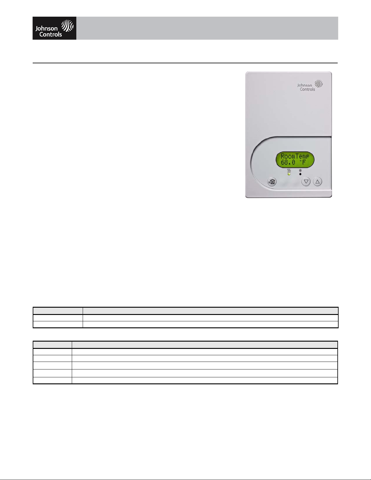
Description
The TEC21x7-4 Series Thermostat
Controllers are N2 networked devices that
provide control of local hydronic reheat valves,
pressure dependent Variable Air Volume
(VAV) equipment f local hydronic reheat
valves, pressure dependent Variable Air
Volume (VAV) equipment with or without local
reheat, or other zoning equipment using an on/
off, floating, or proportional 0 to 10 VDC
control input. The technologically advanced
TEC21x7-4 Series Thermostat Controllers
feature a Building Automation System (BAS)
N2 Bus communication capability that enables
remote monitoring and programming for
efficient space temperature control.
The TEC21x7-4 Series Thermostat
Controllers feature an intuitive User Interface
(UI) with backlit display that makes setup and
operation quick and easy. The thermostat
controllers also employ a unique, ProportionalIntegral (PI) time-proportioning algorithm that
virtually eliminates temperature offset
associated with traditional, differential-based
thermostat controllers.
Refer to the TEC21x7-4 Series N2 Networked
Thermostats with Two Outputs Product
Bulletin (LIT-12011602) for important product
application information.
Features
• BAS N2 open communication — provides
compatibility with a proven communication
network; N2 Bus is widely accepted by
Heating, Ventilating, and Air Conditioning
(HVAC) control suppliers
• password protection option — protects
against unwanted thermostat controller
tampering
• backlit Liquid Crystal Display (LCD) —
offers real-time control status of the
environment in easy-to-read, English plain
text messages with constant backlight that
brightens during user interaction
• on/off, floating, or proportional 0 to 10 VDC
control — offers additional application
flexibility by providing more advanced
control signals
• override interface key — allows easy
access for temporarily overriding the
unoccupied mode
• simplified setpoint adjustment — enables
the user to change the setpoint by simply
pressing the UP/DOWN arrow keys
• two configurable binary inputs — provide
additional inputs for advanced functions
such as remote night setback, service or
filter alarms, motion detector, and window
status
• over 20 configurable parameters — enable
the thermostat to adapt to any application,
allowing installer parameter access without
opening the thermostat cover
• optional discharge air sensor — monitors
unit efficiency
Repair Information
If the TEC21x7-4 Series Thermostat fails to
operate within its specifications, replace the
unit. For a replacement thermostat, contact
the nearest Johnson Controls®
representative.
Selection Chart
Code Number Control Outputs
TEC2127-4 Two On/Off or Floating
TEC2147-4 Two Proportional 0 to 10 VDC
Accessories
Code Number Description
SEN-600-1 Remote Indoor Air Temperature Sensor
SEN-600-4 Remote Indoor Air Temperature Sensor with Occupa ncy Override and LED
TEC-7-PIR
TE-6361M-1
TE-636S-1 Strap-Mount Temperature Sensor
1. The TEC-7-PIR Accessory Cover can be used to replace the existing cover on a non-PIR TEC21x7-4 Thermostat Controller to provide occupancy sensing
2. Additional TE-636xx-x Series 10k ohm Johnson Controls T ype II Thermistor Sensors are available; refer to the TE-6300 Series Temperature Sensors
The performance specifications are nomina l and conf orm to accep table industr y standar ds. For ap plications a t condition s beyond th ese specification s, consult the local Johnson Controls o ffice.
Johnson Controls, Inc. shall not be liable for damages resulting from misapplication or misuse of its products. © 2012 Johnson Controls, Inc.
1
capability.
Product Bulletin (LIT-216320) for more details.
Zone Controller Cover with Occupancy Sensor
2
Duct Mount Air Temperature Sensor
www.johnsoncontrols.com
1 of 2
Page 2
TEC21x7-4 Series N2 Networked Thermostat Controllers with Two Outputs (Continued)
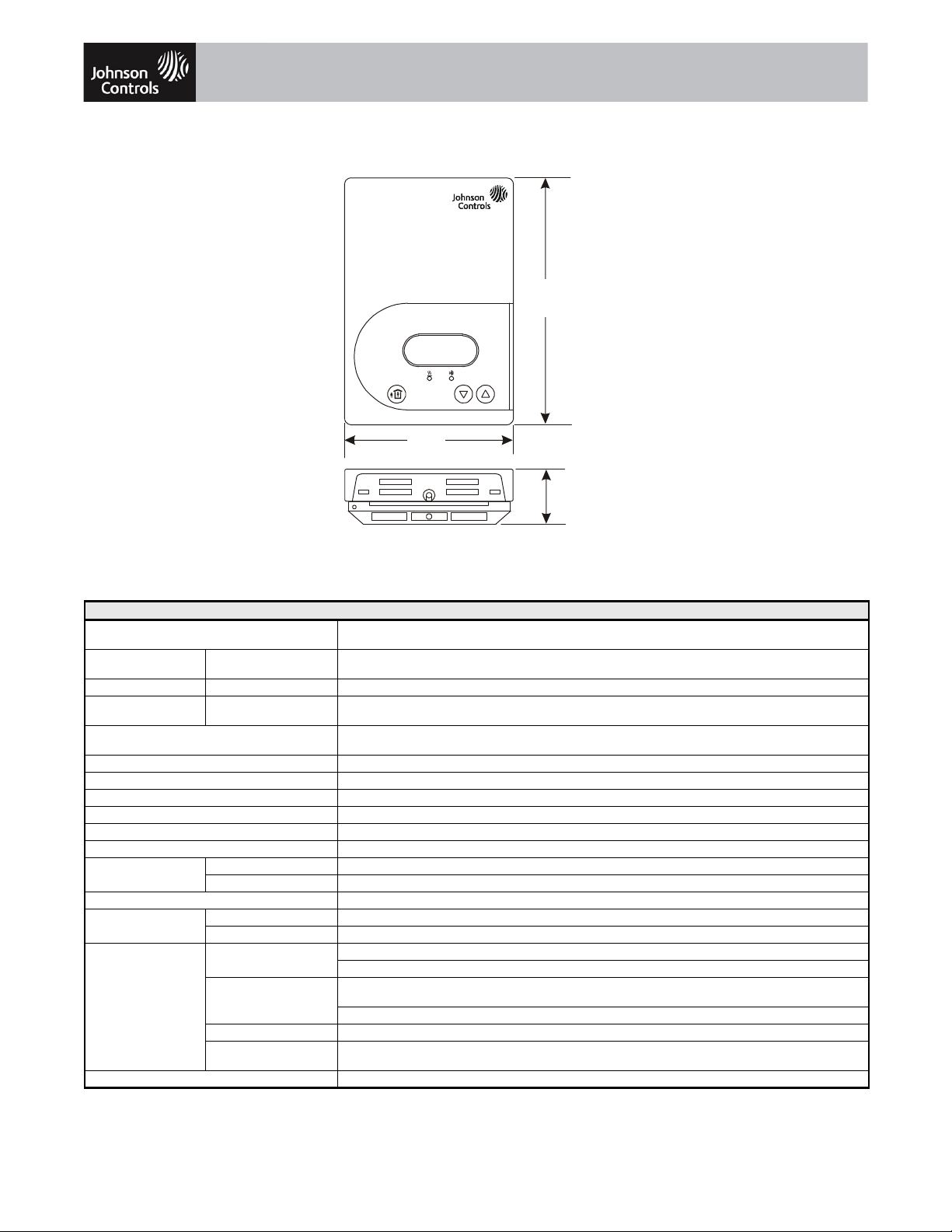
Thermostat Dimensions, in. (mm)
70.0ºF
Room Temp
(125)
3-3/8
(86)
(29)
FIG:dmnsns_21x7
4-15/16
1-1/8
Technical Specifications
TEC21x7-4 Series N2 Networked Thermostat Controllers with Two Outputs
Power Requirements 19 to 30 VAC, 50/60 Hz, 2 VA (Terminals 4 and 5) at 24 VAC Nominal, Class 2 or SafetyExtra-Low Voltage
Relay/Triac Contact
Rating
Analog Output Rating Proportional Control 0 to 10 VDC into 2k ohm Resistance (Minimum)
Auxiliary Output
Rating
Analog Inputs Resistive Inputs (RS and UI3) for 10k ohm Johnson Controls Type II Negative Temperature Coefficient (NTC)
Binary Inputs Voltage-Free Contacts Across Terminal Scom to Terminals BI1, BI2, or UI3
Wire Size 18 AWG (1.0 mm Diameter) Maximum, 22 AWG (0.6 mm Diameter) Recommended
Thermostat Controller Measurement Range -40.0°F/-40.0°C to 122.0°F/50.0°C
Temperature Sensor Type Local 10k ohm NTC Thermistor
Resolution ±0.2F°/±0.1C°
Control Accuracy ±0.9F°/±0.5C° at 70.0°F/21.0°C Typical Calibrated
Control Range Heating 40.0°F/4.5°C to 90.0°F/32.0°C in 0.5° Increments
Default Minimum Deadband 2F°/1C° between Heating and Cooling
Ambient Conditions Operating 32 to 122°F (0 to 50°C); 95% RH Maximum, Noncondensing
Compliance United States UL Listed, File E27734, CCN XAPX, Under UL 873, Temperature Indicating and Regulating Equipment
On/Off and Floating
Control
Triac Output 19 to 30 VAC, 1.0 A Maximum, 15 mA Minimum, 3.0 A In-Rush
Cooling 54.0°F/12.0°C to 100.0°F/38.0°C in 0.5° Increments
Storage -22 to 122°F (-30 to 50°C); 95% RH Maximum, Noncondensing
Canada UL Listed, File E27734, CCN XAPX7,
Europe CE Mark, EMC Directive 2004/108/EC
Shipping Weight 0.75 lb (0.34 kg)
Australia and New
Zealand
(SELV)
30 VAC, 1.0 A Maximum, 3.0 A In-Rush, Class 2 or SELV
Thermistor Sensors
FCC Compliant to CFR 47, Part 15, Subpart B, Class A
Under CAN/CSA C22.2 No. 24, Temperature Indicating and Regulating Equipment
Industry Canada, ICES-003
C-Tick Mark, Australia/NZ Emissions Compliant
The performance specifications are no minal and co nform t o acceptab le ind ustry standar ds. For appl ications at condition s beyond these specifica tions, consult the local Johnson Co ntrols office.
Johnson Controls, Inc. shall not be liable for damages resulting from misapplication or misuse of its products. © 2012 Johnson Controls, Inc.
2 of 2
www.johnsoncontrols.com
 Loading...