

Johnson Controls TEC Series, TEC2101-1, TEC2100 Series, TEC2102-1, TEC2103-1 Product Bulletin
...Page 1
Product Bulletin
Issue Date September 2, 2003
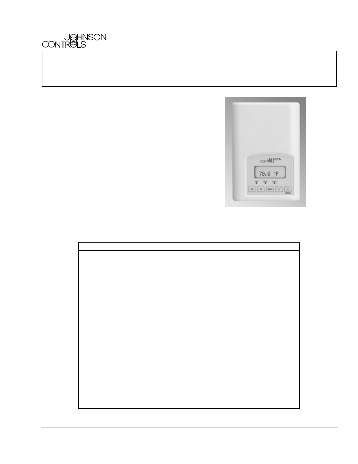
TEC2100 Series Networked Thermostats
The TEC2100 Series of thermostats is a family of
highly advanced thermostats specifically designed for
control of equipment such as rooftop units (with and
without economizers), heat pumps, and single and
multi-stage heating/cooling equipment. The TEC2100
features Metasys® system N2 Bus communication
capability that enables remote monitoring and
programmability for efficient space control. The
TEC2100 used an intuitive, plain text, menu driven
backlit display that makes setup and operation quick
and easy.
The TEC Series includes four models: Single-stage
(TEC2101-1), Heat Pump (TEC2102-1), Multi-stage
(TEC2103-1), and Economizer (TEC2104-1). All
thermostats use a unique proportional control
algorithm that virtually eliminates temperature offset
associated with traditional differential-based
thermostats.
Figure 1: TEC2100 Series Thermostat
Features and Benefits
❑ Metasys N2 Open
Communication
❑ Liquid Crystal Display
(LCD)
Provides compatibility with a proven
communication network; N2 Bus is widely
accepted by Heating, Ventilating, and Air
Conditioning (HVAC) control suppliers
Provides real-time control status of the
environment in easy-to-read plain text
messages
❑ Backlit Display Incorporates a low level back light during
normal operation which brightens during user
interaction
❑ Five Easy-to-Use Interface
Keys
Allow for easy adjustment of the thermostat’s
many options (eliminates the need for
dipswitches)
❑ Two Digital Inputs Provides additional inputs for service or filter
alarms
❑ Over Twenty Configurable
Parameters
❑ Economizer Output
(TEC2104-1)
Enables the thermostat to adapt to any
installation
Controls economizer operation for single and
multi-stage unitary rooftop equipment
© 2003 Johnson Controls, Inc. 1
Code No. LIT-1201660 www.johnsoncontrols.com
Page 2

Product Overview
The TEC2100 Series of thermostats are specifically
designed for networked control of the most common
commercial heating and cooling equipment. In addition
to superior temperature control and application
flexibility, the TEC2100 provides the advantage of the
Metasys N2 Network communication, so the user can
view operation or make adjustments at the thermostat
or from a remote workstation. For local interface, the
plain text menus, backlit display, and five interface
keys make setup and operation of the thermostat
extremely simple.
IMPORTANT: Use this TEC2100 Series
networked thermostats only as an operating control.
Where failure or malfunction of these thermostats
could lead to personal injury or property damage to
the controlled equipment or other property,
additional precautions must be designed into the
system. Incorporate and maintain other devices such
as supervisory or alarm systems or safety or limit
controls intended to warn of, or protect against,
failure or malfunction of the TEC2100 Series
thermostats.
Additional Features
The TEC2100 Series also offers many other features:
• Menu Driven Options
Eliminates the need for dipswitches, setup of all
configurable parameters are menu driven.
• Two Configurable Digital Inputs
Provides additional inputs, configurable for service
or filter alarms at the thermostat. These inputs can
also be user defined at the workstation for other
functions.
• Adjustable Heating/Cooling Deadband
Adjusts the minimum heating/cooling deadband
from 2 to 4F° (1 to 2C°).
• Remote Indoor and Outdoor Sensing
Accommodates remote indoor and outdoor
sensors. Up to three indoor sensors can be
average.
• Adjustable Anti-Short Cycling Timer
Adjusts the minimum on and off times for the
equipment from 0 to 5 minutes.
• Three Levels of Keypad Lockout
Provides three different levels of keypad lockout
that can be set up through the menu and interface
keys.
• Concealed Key to Access Configuration
Parameters
Enables access to all configurable parameters
while limiting unwanted parameter tampering once
the thermostat is set up.
• Three Light-Emitting Diodes (LEDs)
Provides fan, heating, and cooling status at a
glance.
• Adjustable Temporary Occupancy Time
Adjusts the temporary occupancy time from
0 to 12 hours.
• Frost Protection
Turns the heat on when the zone temperature
drops below 42°F (5.5°C) regardless of the
thermostat’s mode.
• Dry Bulb Economizer Function (TEC2104-1)
Provides a 0-10 VDC output for economizer
control. Economizer functions include dry bulb
changeover, minimum damper position, mixed air
temperature setpoint, and control of how
mechanical cooling interacts with economizer
function.
• Adjustable Heating/Cooling Cycles per Hour
Configurable for the number of heating and
cooling cycles in a one-hour period, balancing
temperature control and equipment cycling.
• High and Low Balance Point Adjustments
(TEC2102-1)
Enables more precise control of heat pump
operation based on outside air temperature.
• System Mode Lockout
Allows the heating and cooling modes to be locked
out based on outdoor air temperature when an
outdoor air sensor is connected.
• Non-Volatile EEPROM Memory
Prevents loss of adjusted parameters during
power failure.
• Network Addressing and Viewing
Allows network addressing through the menu
driven user interface. Additionally, for quick
viewing of the N2 address, pressing the YES and
NO keys simultaneously on the user interface
displays the N2 address of the TEC.
2 TEC2100 Series Networked Thermostats Product Bulletin
Page 3

• Remote Access
Allows the user to read and access TEC2100
parameters from an Operator Workstation or
through the N2 Dialer Module (NDM). Binary
inputs or the temperature alarm causes the NDM
to connect to the workstation upon
Change-of-State (COS).
• Heating and Cooling Stage Enable/Disable
(TEC2102-1, TEC2103-1, and TEC2104-1)
Allows operation of the second-stage heating or
cooling to be disabled, reverting the thermostat to
single-stage operation, on heat pump and
multi-stage thermostats.
Thermostat Interface Keys
The TEC2100 interface consists of five keys on the
front cover and one configuration key (see Figure 2)
that can be accessed by removing the front cover. The
functions of the keys are as follows. Use the:
• YES key to confirm a selection and move onto the
next menu item
• NO key when you do not desire a parameter
change, and to advance to the next menu item
• MENU key to access the Main User Menu or exit
the menu
• DOWN arrow key to scroll through menu
selections or adjust values
• UP arrow/SCROLL key to:
− scroll through menu selections or adjust
values
− stop the Status Display Menu from scrolling
and to manually scroll to the next parameter
on the menu. When left unattended for
45 seconds, the display resumes scrolling.
Configuration
Button
Figure 2: Configuration Key Location
Backlit LCD
The TEC2100 uses a two-line, eight-character backlit
display. Low level backlighting is present during
normal operation and it brightens when any user
interface key is pressed. The backlight returns to the
lower level when the thermostat is left unattended for
45 seconds.
Light-Emitting Diodes (LED)s
Three LEDs are used to indicate the status of the fan,
call for heat, or call for cooling on the TEC2101-1,
TEC2103-1, and TEC2104-1. When:
• the fan is on, the FAN LED lights up
• heating is on, the HEAT LED lights up
• cooling is on, the COOL LED lights up
On the TEC2102-1, the three LEDs indicate heat
pump operation. When:
• the fan is on, the FAN LED lights up.
• the auxiliary heat is on, the AUX HEAT LED lights
up.
• the heat-pump compressor is on, the HEAT-PUMP
LED lights up.
Backlit, plain text, Liquid
Crystal Display (LCD)
display is easy to read
in any conditions.
Five keys on the TEC
make operation easy
and intuitive.
75.0ºF
Light Emitting Diodes (LEDs)
indicate system activity.
Figure 3: TEC2100 Front Cover
TEC2100 Series Networked Thermostats Product Bulletin 3
Page 4

Menu Overview
There are three menus used to view, program, and
configure the TEC2100 Series thermostats. The
menus are:
This Installer configuration Menu is used by the
installer/commissioning technician and contains the
following parameters:
• Status Display Menu
• Main User Menu
• Installer Configuration Menu
The following sections outline the functions and
contents of each menu.
Status Display Menu
The Status Display Menu is displayed during normal
thermostat operation. The menu continually scrolls
through the following parameters:
• Room Temperature
• System Mode
• Schedule Status
• Outdoor Temperature (requires outdoor air
temperature sensor)
• Applicable Alarms
Press the up arrow/SCROLL key to temporarily stop
the scrolling.
Main User Menu
The Main User Menu is used to access and change
the thermostat’s basic operating parameters. The
Main User Menu is accessed by pressing the MENU
key during normal thermostat operation. This menu
is most commonly used by the zone occupant and is
comprised of the following parameters:
• Temperature Setpoints
• System Mode
• Fan Mode
The Main User Menu uses Auto Help. Auto Help is
displayed automatically in the Main User Menu when
there is a pause in programming activity.
• Digital Input Configuration
• Keypad Lockout Levels
• Power Delay on Power-up
• Frost Protection
• Maximum Heating Setpoint/Minimum Cooling
Setpoint
• Anti-Short Cycle Timings
• Heating Stages Cycles per Hour
• Cooling Stages Cycles per Hour
• Minimum Deadband
• Heating Fan Control
• End of Cycle Fan Delay
• Temporary Occupancy Time
• Room Sensor Calibration
• Outdoor Air Sensor Calibration
• Number of Heating Stages (TEC2103-1 and
TEC2104-1 only)
• Number of Cooling Stages (TEC2103-1 or
TEC2104-1) Number of Heat Pump Stages
(TEC2102-1)
• Outdoor Air Temperature Heating Lockout
• Outdoor Air Temperature Mechanical Cooling
The following parameters are for the TEC2102-1
only:
• Low Balance Point
• High Balance Point
• Comfort/Economy Heat Pump Operation
• Reversing Valve Operation
• Compressor/Auxiliary Interlock
Installer Configuration Menu
The Installer Configuration Menu is used to set up
the thermostat for application specific operation. The
menu is accessed by removing the front cover and
pressing the configuration key, labeled CONFIG
(see Figure 2).
4 TEC2100 Series Networked Thermostats Product Bulletin
The following parameters are for the TEC2104-1
only:
• Outdoor Air Changeover Setpoint
• Outdoor Air Damper Minimum Position
• Mechanical Cooling Enable/Disable with
Economizer Operation
• Mixed Air Temperature Setpoint
• Mixed Air Temperature Display
Page 5

Dimensions
4.94
125
75.0ºF
3.38
86
1.13
29
Figure 4: TEC2100 Dimensions (in./mm)
Ordering Information
Code Number Description Applications
TEC2101-1
TEC2102-1
TEC2103-1
TEC2104-1
Networked Single-Stage Thermostat
Networked Heat Pump Thermostat Heat Pump with up to 3 Heating/2 Cooling Stages
Networked Multi-Stage Thermostat Multi-staged Packaged Heating/Cooling Equipment
Networked Multi-Stage,
Economizer Thermostat
Fan Coil Unit, Unit Heaters, and Single-Stage Packaged
Heating/Cooling Equipment
Packaged Rooftop Units with Economizers
Accessories
Code Number Description
SEN-600-1
SEN-600-2
SEN-600-3
Remote Indoor Temperature Sensor
Outdoor Air Temperature Sensor
Duct Mount Temperature Sensor
TEC2100 Series Networked Thermostats Product Bulletin 5
Page 6

Technical Specifications
TEC2101-1 Thermostat with N2 Bus, Single-Stage
Product
Power Requirements
Relay Contact Rating
Maximum Inductive
Digital Inputs
Economizer Output
Recommended Wire Size
Thermostat Measurement
Range
Sensor Type:
Resolution:
Control Accuracy
Outdoor Air Temperature
Indication Range
Control Range
Minimum Deadband
Ambient Operating
Conditions
Ambient Storage
Conditions
Dimensions (H x W x D)
Shipping Weight
UL and cUL Listing
CE Compliance
FCC Compliance
The performance specifications are nominal and conform to acceptable industry standards. For application at conditions beyond these
specifications, consult the local Johnson Controls office. Johnson Controls, Inc. shall not be liable for damages resulting from misapplication or
misuse of its products.
This device complies with Class A Part 15 of the FCC rules. It was also verified to Class B. Operation is subject to
the following two conditions:
(1) This device may not cause harmful interference.
(2) This device must accept any interference received, including interference that may cause undesired operation.
This Class A digital apparatus meets all of the requirements of the Canadian Interference-Causing Equipment
Regulations. Cet appareil numérique de la Classe A respecte toutes les exigences du Règlement sur le materiél
brouilleur du Canada.
TEC2102-1 Thermostat with N2 Bus, Heat Pump
TEC2103-1 Thermostat with N2 Bus, Multi-Stage
TEC2104-1 Thermostat with N2 Bus, Multi-Stage with Economizer Control
20-30 VAC, 50/60 Hz, 24 VAC nominal, Class 2
1 ampere with in-rush surges up to 3 amperes, 30 VAC maximum, Class 2
Relay dry contact only across the C terminal to DI1 and DI2
0 to 10 VDC into 2K ohm resistance minimum (TEC2104-1 only)
18 gauge maximum, 22 gauge recommended
-40 to 122°F (-40 to 50°C)
Local 10K ohm NTC thermistor
± 0.2F° (± 0.1C°)
± 0.9F° (± 0.5C°) @ 70°F (21°C) typical calibrated
-40 to 122°F (-40 to 50°C)
Cooling: 54 to 100°F (12 to 37.5°C) in 1/2 degree increments
Heating: 40 to 90°F (4.5 to 32°C) in 1/2 degree increments
(Between heating and cooling) 2F° or 1C°
32 to 122°F (0 to 50°C); 0 to 95% RH noncondensing
-22 to 122°F (-30 to 50°C); 0% to 95% RH noncondensing
4.94 x 3.38 x 1.13 in. (125 x 86 x 29 mm)
0.75 lb (0.34 kg)
File E27734 with CCN’s XAPX (US, UL 873) and XAPX7 (Canada, CSA C22.2 No. 24)
CE Directives EN50091-1: 1992 EMC Emissions; EN50082-2 EMC Immunity (Pending)
This equipment has been tested and found to comply with the limits for a Class A digital
device and verified to Class B pursuant to Part 15 of FCC Rules. These limits are designed
to provide reasonable protection against harmful interference when this equipment is
operated in a commercial environment. This equipment generates, uses, and can radiate
radio frequency energy and, if not installed and used in accordance with the instruction
manual, may cause harmful interference to radio communications.
Controls Group
507 E. Michigan Street
P.O. Box 423 Published in U.S.A.
Milwaukee, WI 53201 www.johnsoncontrols.com
6 TEC2100 Series Networked Thermostats Product Bulletin
 Loading...