

Page 1
The T-5800 Series ReceiverControllers are designed for use
with remote temperature, humidity,
or pressure transmitters
(connected to the controlled
variable “CV” input) to provide
precise control of pneumatic
devices. The T-5800-3 is a dual
input proportional-only receivercontroller with field selectable
local or remote set point. The
T-5800-4 is also a dual input
receiver-controller with field
selectable local or remote set
point; however, this model
provides proportional plus integral
(PI) control. In addition, an
automatic/manual integral control
cutout feature is incorporated into
the T-5800-4 design. Utilizing the
fan “F” connection, this feature
allows the system to start up using
proportional-only control thus
keeping the system from going out
of control on startup, as is inherent
to PI (automatic reset) controllers,
when the system has been off for
some time. Refer to Product Data
T-5800 for instrument
specifications and additional
details.
Pneumatic Control Manual 717.1
Receiver-Controllers Section
Technical Bulletin T-5800-3/-4
Issue Date 0586
T-5800-3 and T-5800-4
Dual Input Receiver-Controllers
Installation and Calibratio n
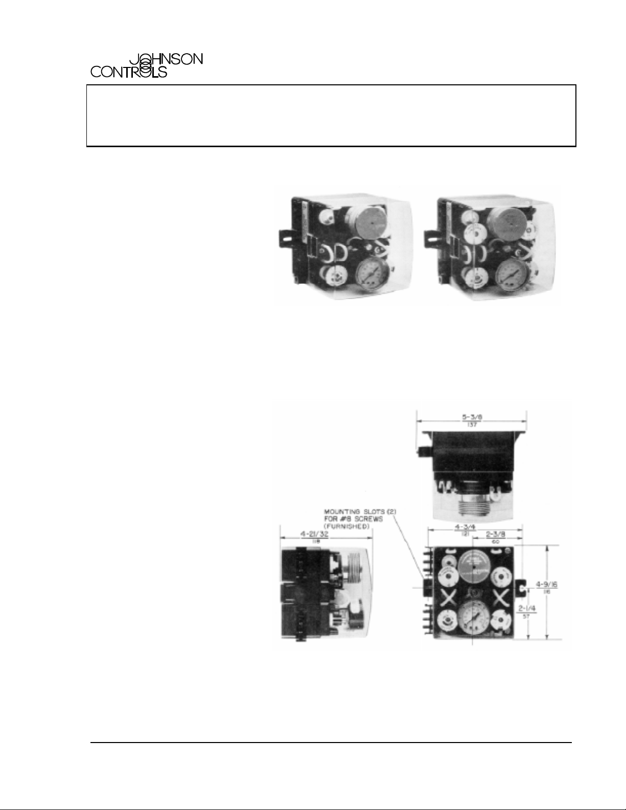
Fig. 1: T-5800-3 Dual Input Fig. 2: T-5800-4 Dual Input
Proportional Receiver-Controller PI Receiver-Controller
Installation
The T-5800 Series ReceiverControllers are designed for
surface mounting; refer to Fig. 3
for space requirements and
mounting details. All air line
connections are made to the units
through two snap-on input/output
connectors which have barbed
fittings for 1/4 in. O.D. polytubing.
Both dual input models are
furnished with a clear cover, snapon air connectors, a double
.007 in. orifice jumper, an
additional set point dial sticker
marked with 50 graduations, and a
yellow remote indication set point
dial sticker.
© 1986 Johnson Controls, Inc.
Part No. 24-7029-0, Rev. —
Code No. LIT-7171320X
Fig. 3: T-5800 Series Dimensions in./mm and Mounting Details
1
Page 2
Cover Removal
The cover can be removed by
applying an inward pressure to
one of the black tabs of the
receiver-controller main body to
unlatch it. The cover can also
be removed by simply taking
hold of the top and bottom sides
of the cover and pulling outward.
Oil Indicating Supply Air Filter
Check the oil indicating supply
air filter and replace as
necessary (A-4000-137 ordered
separately). When the filter is
dirty, a pressure drop will occur.
When filtering oil-contaminated
air, the filter will change from
white to red in color. If frequent
changes are necessary, check
the air supply system to
determine the cause of dirty or
oil-contaminated air.
Positioning the Action and
Orifice Jumpers
The T-5800 must be
programmed according to the
system requirements. Both dual
input receiver-controllers are
factory set in the direct acting
mode with reverse readjustment.
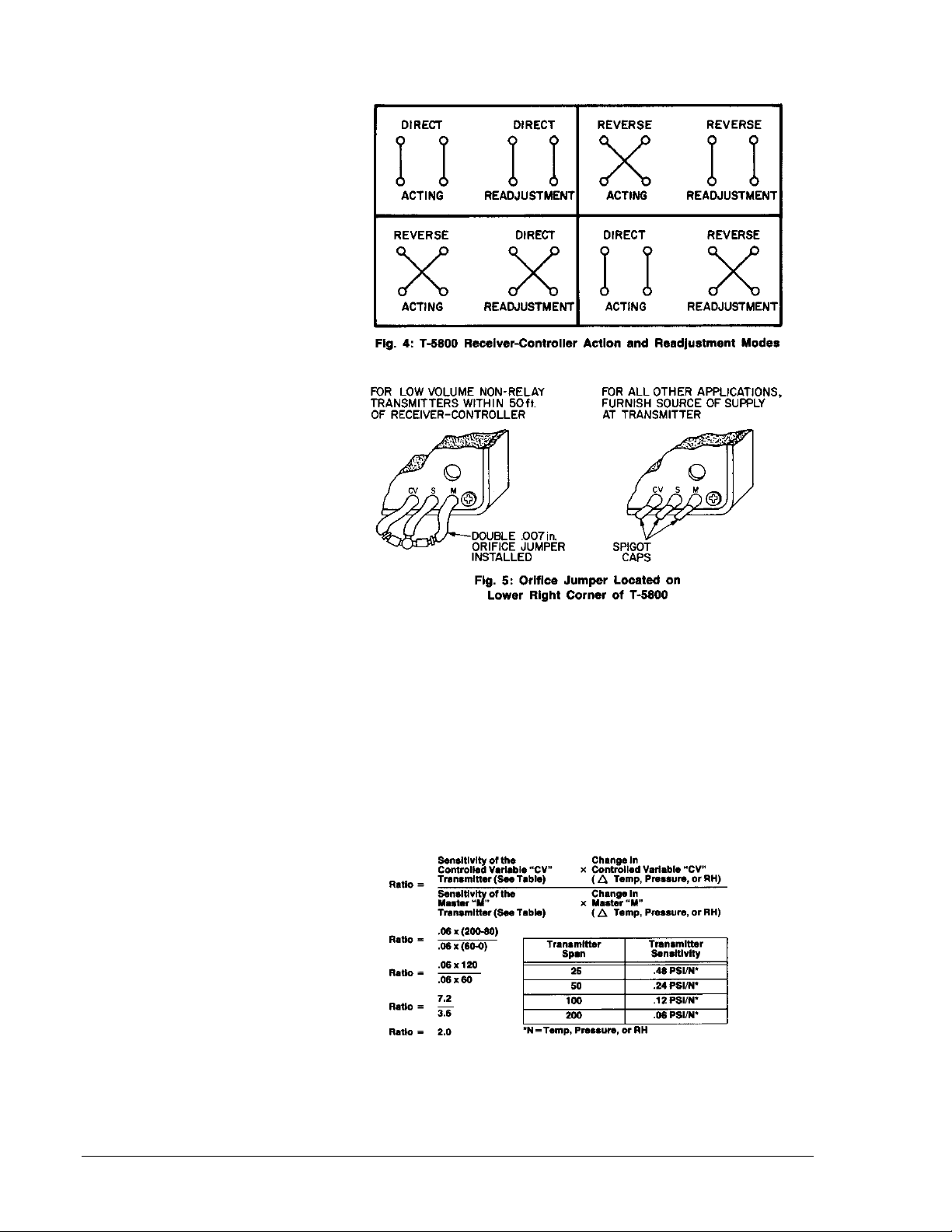
The action and readjustment can
be changed by interchanging the
placement of the tube ends from
one lower spigot to the other
lower spigot (see Figs. 4, 11,
and 15).
Each dual input T-5800 is
furnished with a double .007 in.
orifice jumper and three yellow
spigot caps (see Fig. 5). The
orifice jumper provides a
restricted source of supply to low
volume non-relay type
transmitters. For best results, it
is recommended that this jumper
be used when the low volume
transmitter is located within 50 ft.
(15m) of the receiver-controller.
For all other applications, it is
recommended that the spigots
be capped and a source of
supply be furnished at the
transmitter.
Precalibration Setup
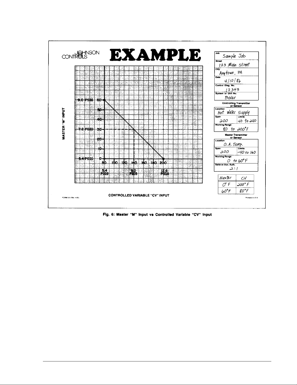
Using the graph on Form 561,
prepare a readjustment
schedule (similar to the example
in Fig. 6) with respect to job
requirements, action, range of
readjustment, transmitter spans,
and pressures. Use the graph
and transmitter span vs. output
comparison chart
to illustrate the pressure
relationship of master “M” input
vs. controlled variable “CV”
input. Locate the two end points
of the control schedule and
connect with a straight line.
The receiver-controller ratio is
determined by the following
formula:
2 T-5800-3/T-5800-4 Technical Bulletin
Page 3
Set point Selection - Local or
Remote
Local: The arrow on the set
point dial represents
approximately a 9 PSIG (63 kPa)
set point pressure. The dial
sticker is designed so that the
actual set point can be written
directly on its surface using a
common pencil.
Note: When local set point
adjustment is used, the set
point “SP” connection must
be open to atmosphere.
Remote: Rotate the set point
dial fully counterclockwise until it
hits its mechanical stop. Affix
the yellow dial sticker to indicate
remote set point adjustment
mode (see Fig 7). Connect the
tubing from the remote set point
adjustment device to the set
point “SP” connection of the
snap-on input/output connector.
A low volume restricted source
of supply air (less than .005 in.
orifice) is automatically
furnished; therefore, use 75% of
the overall line length that is
recommended for a .005 in.
orifice.
FC and PRV Test Points
The FC and PRV test points and
their associated adjustments are
for FACTORY USE ONLY.
Supply Air Interruptions
Both dual input receivercontrollers have within their
circuitry a master balance
regulator which requires that the
supply air remain on at all times.
In addition, T-5800-4 has an
automatic/manual integral
control cutout feature which also
requires that the supply air
remain on at all times.
Calibration
General Instructions
Calibration and readjustment of
the T-5800 Receiver-Controller
should only be done by a
qualified Johnson Controls
T-5800-3/T-5800-4 Technical Bulletin 3
Page 4
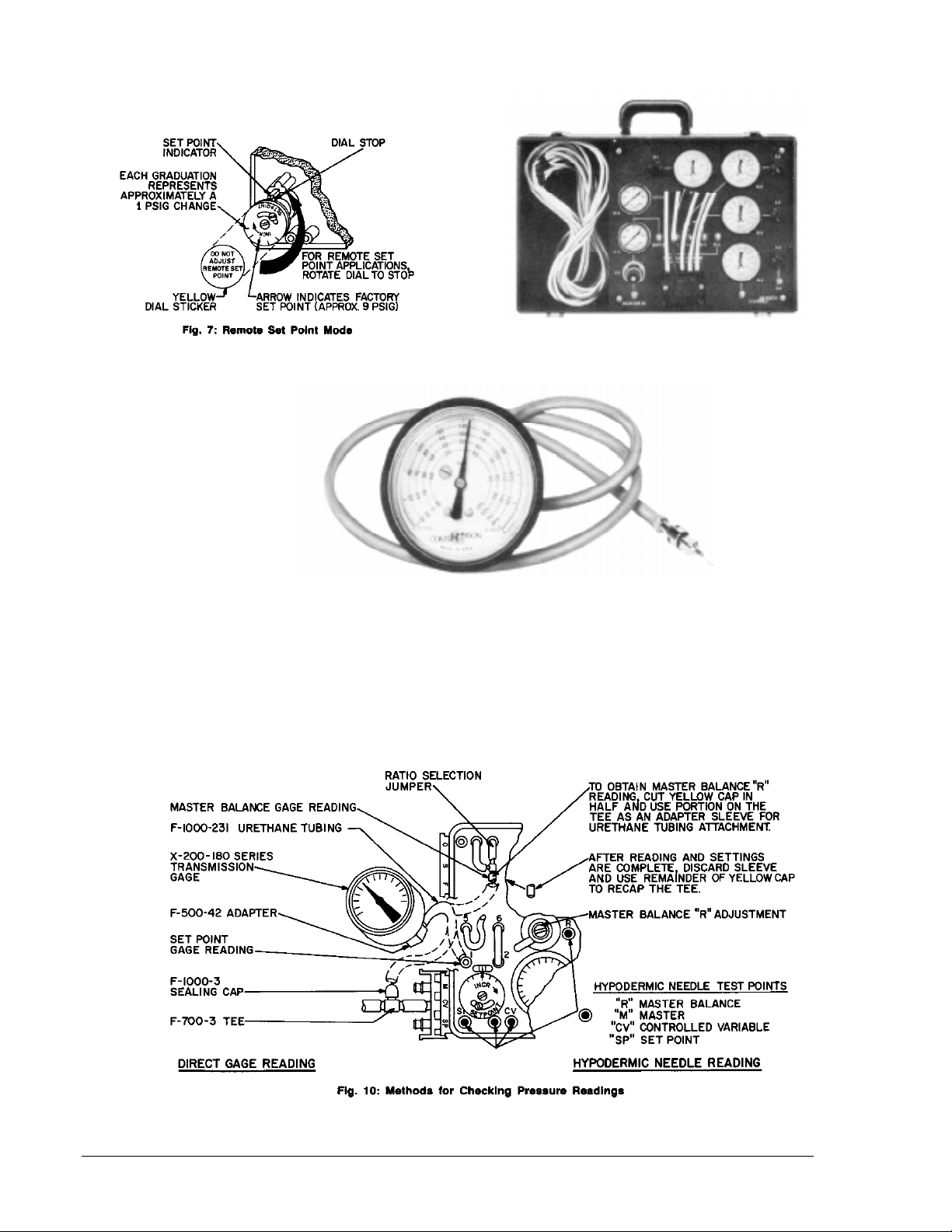
Fig. 8: X-200-173 Calibration Kit
Fig. 9: X-200-140 Test Probe with
X-200-180 Series Transmission Gage and
F-500-42 Adapter
4 T-5800-3/T-5800-4 Technical Bulletin
Page 5
representative equipped with the
proper tools. An X-200-173
Calibration Kit (see Fig. 8,
ordered separately) is available
for making adjustments and
pressure checks on the T-5800.
This kit provides all of the
necessary gages, regulators,
and connectors for a more
convenient and quicker
calibration procedure.
An X-200-140 Hypodermic
Needle Test probe and
appropriate gage (see Fig. 9,
ordered separately) is also
available for troubleshooting,
test point readings, or final set
point adjustments under actual
job conditions. Note: Figure 10
illustrates an alternative
method of checking pressure
readings on the T-5800 where
use of a hypodermic needle
test probe is prohibited.
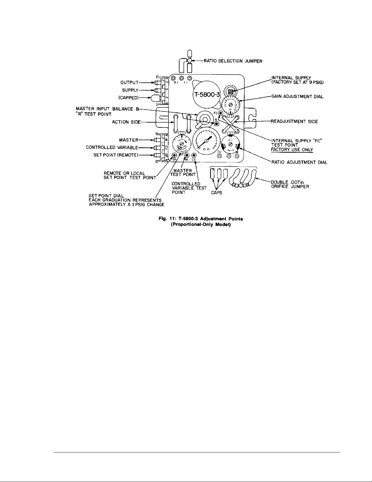
Calibrating the T-5800-3
(See Fig. 11)
With the supply air ON, balance
the receiver-controller by setting
the following:
• Adjust the local set point dial
or the remote adjuster
(manual or automatic) to
produce 9 PSIG (63 kPa)
using the appropriate
method and gage as
described above.
• Turn the gain dial clockwise
so that the word
“INCREASE” imprinted on
the dial is centered with the
dial reference point.
• Install the ratio selection
jumper in the correct position
(see Fig. 11). If the
calculated ratio is less than
or equal to 2.5:1, (as is the
case with the example where
the calculated ratio is 2:1),
the jumper should be
installed in the 1:1 position.
If the calculated ratio is
greater than 2.5:1, the
jumper should be installed in
the 3:1 position.
• Turn the ratio dial so that
“1:1 (3:1)” imprinted on the
dial lines up with the dial
reference point.
Receiver-Controller Preset
(See Example Fig. 6)
Utilize one of the pressure
checking methods described
previously to obtain a master “M”
input pressure reading, a master
balance “R” pressure reading,
and a controlled variable “CV”
input pressure reading.
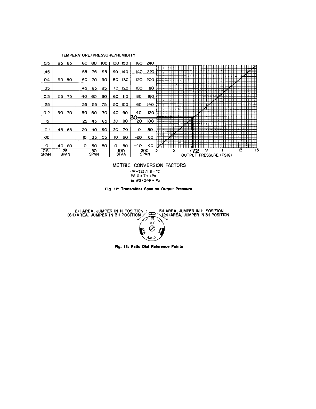
1. Apply a master “M” input
pressure equal to the
midpoint of the desired
working range (Example:
30°F on a 0 to 60°F working
range or 7.2 PSIG as
highlighted in Fig. 12).
T-5800-3/T-5800-4 Technical Bulletin 5
Page 6
2. Rotate the master balance
screw (see Fig. 10) located
in the center of the receivercontroller (clockwise to
increase or counterclockwise
to decrease) to produce a
9 PSIG (63 kPa) gage
reading at the master
balance “R” reference.
Doing so will shift the
working range (internally) to
a more linear portion of the
ratio circuit.
6 T-5800-3/T-5800-4 Technical Bulletin
3. Vary the master input from
minimum to maximum over
its working range (Example:
0 to 60°F or 5.4 to 9 PSIG
per Fig. 6). Note: The
master “M” INPUT is
limited to not less than
2 PSIG nor greater than
17 PSIG. Note the
pressure readings at the
master balance “R”
reference corresponding
to these minimum and
maximum points.
If the minimum master
balance “R” pressure noted
above is greater than or
equal to 5 PSIG and the
maximum master balance
“R” pressure is less than
19 PSIG (with a 20 PSIG
supply), no further
adjustments are required. If
the minimum master
balance “R” pressure is less
than 5 PSIG, rotate the
master balance screw
(clockwise to increase) so
that the minimum pressure
is greater than 5 PSIG and
the maximum does not
exceed 19 PSIG.
Page 7
4. After removing the pressure
checking method from the
master balance “R”
reference, it is suggested
that the master balance
screw be sealed (using a
small dab of fingernail
polish).
5. Return the master “M” input
pressure to the midpoint of
the desired working range
(Example: 30°F or 7.2 PSIG
on a 0 to 60°F working
range per Fig. 6).
6. Apply a controlled variable
“CV” input pressure to the
value corresponding to the
value 7.2 PSIG master “M”
input setting (Example:
140°F or 9 PSIG per Fig. 6).
7. Rotate the ratio dial (see
Fig. 13) to a position which
most closely represents the
required ratio setting
(Example: 2:1, outer scale
on dial and jumper in 1:1
position).
8. Adjust the local set point
dial or the remote adjuster
(manual or automatic) to
produce an output pressure
on the controller gage equal
to the midpoint of the spring
range of the controlled
device.
Ratio and Set Point Checkout
1. Apply the minimum master
“M” input pressure value
(Example: 0°F or 5.4 PSIG
per Fig. 6).
2. Apply the corresponding
controlled variable “CV”
input pressure value
(Example: 200°F or
12.6 PSIG per Fig 6).
3. Ratio Dial Adjustment:
Note: Never adjust the
ratio dial when the master
“M” Input pressure is at
the midpoint of its
working range (Example:
30°F on a 0 to 60°F range
or 7.2 PSIG per Fig. 12).
No output signal change
will occur because the
internal ratio circuitry is in
a balanced condition, and
any previous ratio dial
setting (if not marked) will
be lost.
Adjust the ratio dial to cause
the receiver-controller
output to be at a pressure
value which would produce
the required controlled
variable “CV” input
(Example: Direct acting T5800-3, N.O. heating valve
with a 3 to 7 PSIG spring
range; output should be
below the midpoint of the
spring range of the valve
which would produce the
required 200°F).
4. Apply the maximum master
“M” input pressure value
(Example: 60°F or 9 PSIG
per Fig. 6).
5. Apply the corresponding
controlled variable “CV”
input pressure value
(Example: 80°F or
5.4 PSIG per Fig. 6).
6. Set Point dial Adjustment:
Adjust the set point dial to
cause the output pressure
to be at the opposite end of
the spring range of the
controlled device (Example:
Direct Acting T-5800-3, N.O.
heating valve with a
3 to 7 PSIG spring range;
output should be above the
midpoint of the spring range
of the valve which would
produce the required 80°F).
7. Rotate the gain dial so that
“10:1” imprinted on the dial
lines up with the dial
reference point.
8. The T-5800-3 is calibrated
and ready for system
operation.
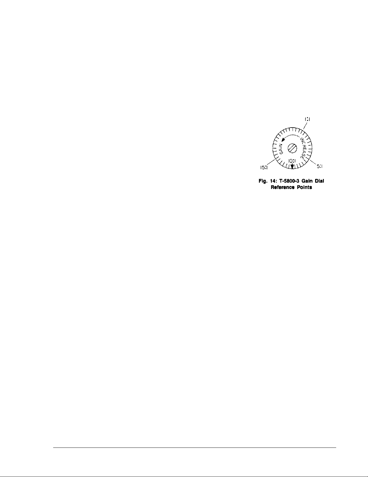
Gain Adjustment (See Fig. 14)
Adjusting the gain dial will not
affect the controller set point;
however, the output pressure
may change when the gain dial
is adjusted. Increasing the gain
will narrow the throttling range
(decrease offset), allowing the
control point to be closer to the
set point. Decreasing the gain
will widen the throttling range,
forcing the control point away
from the set point.
Normally, having the gain arrow
set at the pointer represents a
reasonable gain adjustment
which would provide stability.
Increase the gain setting by
small increments until the
system becomes unstable and
begins to cycle. Decrease the
gain setting slightly to remove
the cycling effect. Doing so will
provide maximum controllability
with a minimum of offset.
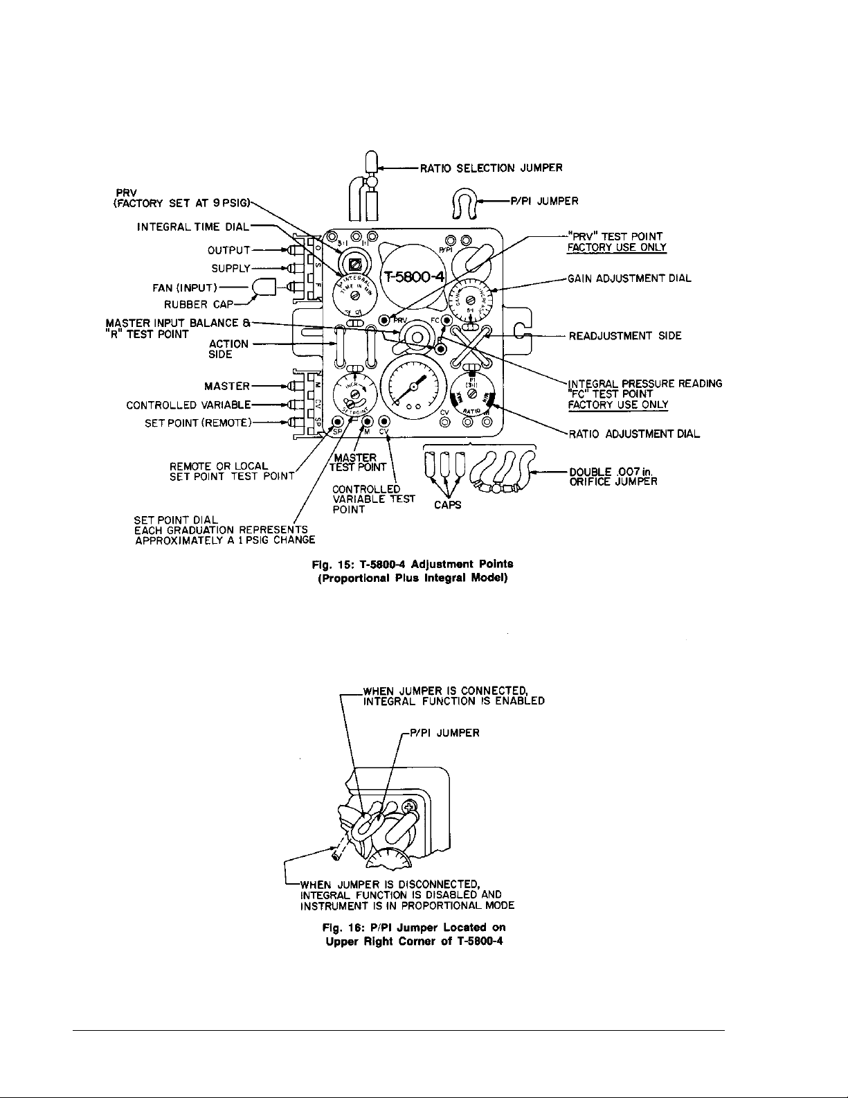
Calibrating the T-5800-4
(see Fig. 15)
When connecting the T-5800-4
Receiver-Controller to an
operating system, the fan “F”
connection should either have
the “system in operation”
function signal (minimum of
12 PSIG) attached (example:
fan on-off or water circulation
pump on-off), or the connection
must be capped.
Pulling the P/PI jumper (see
Fig. 16) off of its spigot causes
the receiver-controller to operate
as proportional-only controller
(no integral function). The
jumper must be connected
T-5800-3/T-5800-4 Technical Bulletin 7
Page 8
8 T-5800-3/T-5800-4 Technical Bulletin
Page 9

in order for the system to have
normal proportional plus integral
control.
The T-5800-4 has an
automatic/manual integral
control cutout feature when the
fan “F” connection is used. This
feature keeps the system from
going out of control on startup
(after it’s been off for some time)
by allowing the system to start
up using proportional-only
control. If it is determined that
there is not a need for the cutout
feature, cap the unused fan “F”
connection. Doing so will allow
normal proportional plus integral
control of the system at all
times, provided that the P/PI
jumper is connected.
With the supply air ON, balance
the receiver-controller by setting
the following:
• Pull the P/PI jumper off of its
spigot so that the receivercontroller will operate as a
proportional-only controller
(no integral function).
• Adjust the local set point dial
or the remote adjuster
(manual or automatic) to
produce 9 PSIG (63 kPa)
using the appropriate
method and gage as
described previously.
• Install the ratio selection
jumper in the correct position
(see Fig. 15). If the
calculated ratio is less than
or equal to 2.5:1 (as is the
case with the example where
the calculated ratio is 2:1),
the jumper should be
installed in the 1:1 position.
If the calculated ratio is
greater than 2.5:1, the
jumper should be installed in
the 3:1 position.
• Turn the ratio dial so that
“1:1 (3:1)” imprinted on the
dial lines up with the dial
reference point.
Receiver-Controller Preset
(See Example Fig. 6)
Utilize one of the pressure
checking methods described
previously to obtain a master “M”
input pressure reading, a master
balance “R” pressure reading,
and a controlled variable “CV”
input pressure reading.
1. Apply a master “M” input
pressure equal to the
midpoint of the desired
working range (Example:
30°F on a 0 to 60°F working
range or 7.2 PSIG as
highlighted in Fig. 12).
2. Rotate the master balance
screw (see Fig. 10) located
in the center of the receivercontroller (clockwise to
increase or counterclockwise
to decrease) to produce a
9 PSIG (63 kPa) gage
reading at the master
balance “R” reference.
Doing so will shift the
working range (internally) to
a more linear portion of the
ratio circuit.
3. Vary the master input from
minimum to maximum over
its working range (Example:
0 to 60°F or 5.4 to 9 PSIG
per Fig. 6). Note: The
master “M” INPUT is
limited to not less than
2 PSIG nor greater than
17 PSIG. Note the pressure
readings at the master
balance “R” reference
corresponding to these
minimum and maximum
points.
If the minimum master
balance “R” pressure noted
above is greater than or equal
to 5 PSIG and the maximum
master balance “R” pressure
is less than 19 PSIG (with a
20 PSIG supply), no further
adjustments are required. If
the minimum master balance
“R” pressure is less than
5 PSIG, rotate the master
balance screw (clockwise to
increase) so that the minimum
pressure is greater than
5 PSIG and the maximum
does not exceed 19 PSIG.
4. After removing the pressure
checking method from the
master balance “R”
reference, it is suggested
that the master balance
screw be sealed (using) a
small dab of fingernail
polish).
5. Return the master “M” input
pressure to the midpoint of
the desired working range
(Example: 30°F or 7.2 PSIG
on a 0 to 60°F working
range per Fig. 6).
6. Apply a controlled variable
“CV” input pressure to the
value corresponding to the
7.2 PSIG master “M” input
setting (Example: 140°F or
9 PSIG per Fig. 6).
7. Rotate the ratio dial (see
Fig. 13) to a position which
most closely represents the
required ratio setting
(Example: 2:1, outer scale
on dial and jumper in
1:1 position).
8. Adjust the local set point dial or
the remote adjuster (manual or
automatic) to produce an
output pressure on the
controller gage equal to the
midpoint of the spring range of
the controlled device.
Ratio and Set Point Checkout
1. Apply the minimum master
“M” input pressure value
(Example: 0°F or 5.4 PSIG
per Fig. 6).
2. Apply the corresponding
controlled variable “CV”
input pressure value
(Example: 200°F or
12.6 PSIG per Fig 6).
3. Ratio Dial Adjustment:
Note: Never adjust the ratio
dial when the master “M”
Input pressure is at the
midpoint of its working
range (Example: 30°F on a
0 to 60°F range or 7.2 PSIG
per Fig. 12). No output
signal change will occur
because the internal ratio
circuitry is in a balanced
condition, and any previous
ratio dial setting (if not
marked) will be lost.
Adjust the ratio dial to cause
the receiver-controller
output to be at the midpoint
T-5800-3/T-5800-4 Technical Bulletin 9
Page 10
of the actual spring range of
the controlled device.
4. Apply the maximum master
“M” input pressure value
(Example: 60°F or 9 PSIG
per Fig. 6).
5. Apply the corresponding
controlled variable “CV”
input pressure value
(Example: 80°F or
5.4 PSIG per Fig. 6).
6. Set Point Dial Adjustment:
Adjust the set point dial to
cause the output pressure
to be at the midpoint of the
actual spring range of the
controlled device.
7. Start up the system to be
controlled. After a
reasonable period of time,
the receiver-controller
should be in control (as a
proportional-only controller)
WITHIN the throttling range
of the controlled device.
8. Proceed to the Gain
Adjustment section.
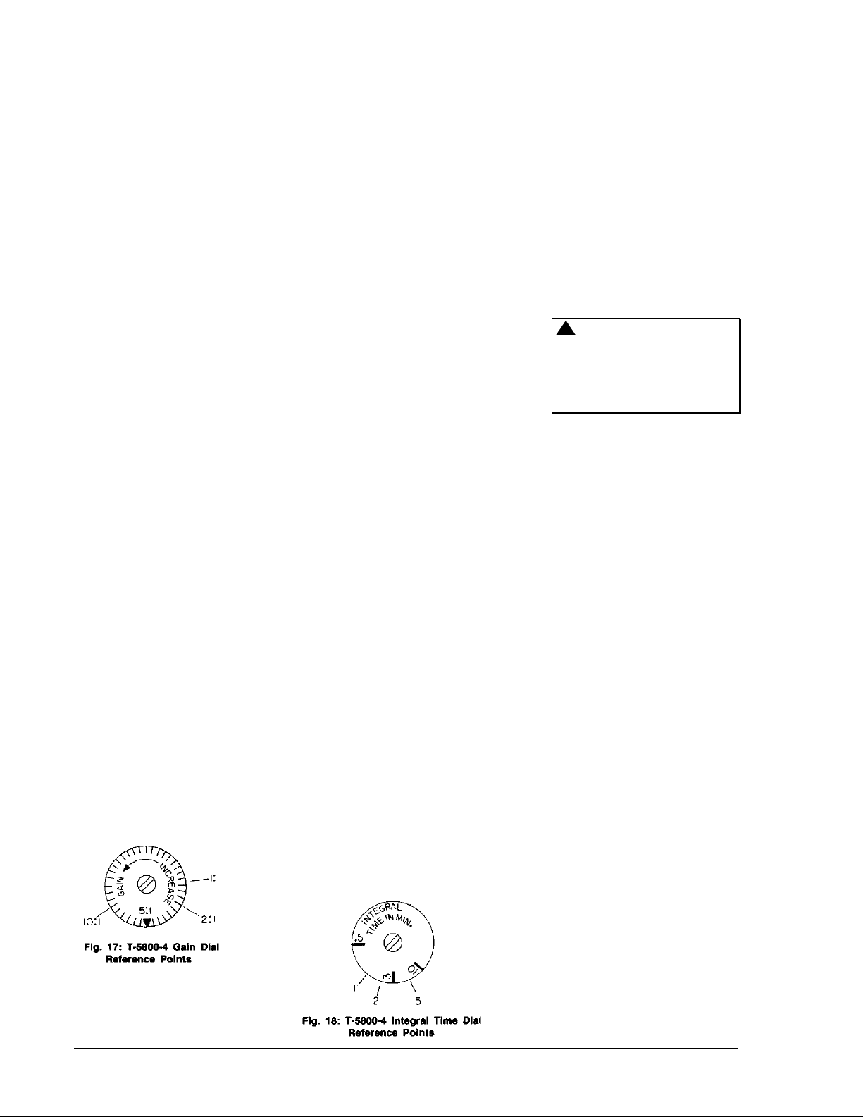
Gain Adjustment (See Fig. 17)
Note: All gain adjustments
must be made with the P/PI
jumper still removed from the
spigot.
Adjusting the gain dial will not
affect the controller set point;
however, the output pressure
may change when the gain dial
is adjusted. Increasing the gain
will narrow the throttling range
(decrease offset), allowing the
control point to be closer to the
set point. Decreasing the gain
will widen the throttling range,
forcing the control point away
from the set point.
Increase the gain setting by
small increments until the
system becomes unstable and
begins to cycle. Decrease the
gain setting slightly to remove
the cycling effect and mark this
position on the dial. Rotate the
dial fully clockwise until it hits its
mechanical stop, then
counterclockwise to the midpoint
between the stop and the
marked position. Doing so will
provide a suitable gain to allow
the introduction of the integral
function.
After the system stabilizes
again, reconnect the P/PI jumper
to return the integral function to
the receiver-controller. After a
reasonable period of time, the
control point should stabilize at
the set point value and no
further adjustments will be
required. If the control point
does not stabilize at the set
point value or if excessive
cycling occurs, proceed to the
Integral Time Adjustment
section.
Integral Time Adjustment
(See Figs. 17 & 18)
Adjusting the integral time dial
will not affect the controller set
point. If the system response
toward the set point is too slow,
decrease the integral time
and/or increase the gain dial
settings by small increment
each. If cycling occurs,
increase the integral time and/or
decrease the gain dial settings
by small increments each.
Using the appropriate pressure
checking method described
previously, note the exact set
point pressure value. Upset the
system by rotating the set point
dial to force the controlled
device to an open position. Wait
a sufficient period of time to
cause controlled variable
deviation, then return the set
point dial to its original position
producing the noted pressure. If
the system response is not as
desired, adjust the integral time
and gain dials as prescribed
above to obtain the desired
system response.
System Startup Response
The following procedure is for
determining whether an
additional time delay is required
for proper system startup.
!
WARNING: Before
stopping a system, be sure
that a change in output
pressure will not upset the
system and cause
damage.
A. Receiver-controllers
Using Fan “F” Connection
When the system becomes
stable, stop the system and
allow enough time to pass
until the controlled variable
deviates from the set point.
(Remember when the system
is off, the receiver-controller
returns to proportional-only
control. This feature
eliminates integral windup
during off periods.) Restart
the system and observe to
see how well it comes into
control. When the system is
started and the fan signal is
increased to maximum
(20 PSIG), the proportionalonly controller returns to
proportional plus integral
control to cause the control
point to equal the set point. If
the system response is not as
desired, determine whether
the cause is an improper time
delay (see T-5800-100 Time
Delay section) or an incorrect
integral time setting (repeat
Integral Time Adjustment
procedure above).
Normally, having the gain arrow
set at the pointer represents a
reasonable gain adjustment
which would provide stability.
10 T-5800-3/T-5800-4 Technical Bulletin
Page 11
B. Receiver-Controllers
Having Fan “F”
Connection Capped
(System ON 100% of the
Time)
When the system becomes
stable, stop the system and
disconnect the P/PI jumper.
Allow enough time to pass
until the controlled variable
deviates from the set point.
Restart the system,
reconnect the P/PI jumper,
and observe to see how well
the system comes into
control. If the system
response is not as desired,
repeat the Integral Time
Adjustment procedure
above.
Note: If the system is
shut down (power failure,
cleaning, repair, etc.), the
P/PI jumper must be
disconnected and left
vented for a period of time
equal to the integral time
dial setting. Start up the
system and reconnect the
P/PI jumper when the
system becomes stable.
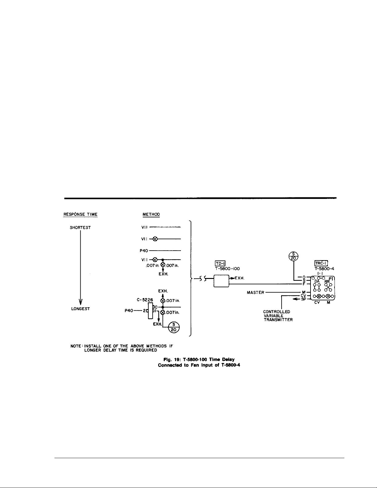
T-5800-100 Time Delay (When
Fan “F” Connection is Used)
After system startup, if the
system response is too slow, the
integral control function will act
on the signal before the
proportional control function
settles out. To eliminate this
problem, a T-5800-100 Time
Delay (ordered separately) must
be added to the fan “F”
connection (see Fig 19). This
device will delay the pressure
increase to the fan “F”
connection of the receivercontroller, allowing more time for
the system to achieve stable
proportional control before the
integral control function is
initiated.
T-5800-3/T-5800-4 Technical Bulletin 11
Page 12

Notes
Controls Group
507 E. Michigan Street
P.O. Box 423 Printed in U.S.A.
Milwaukee, WI 53202
12 T-5800-3/T-5800-4 Technical Bulletin
 Loading...