

Page 1

24-10239-480 Revision F
December 2017
hardware installation
S321-IP
Network Controller
Page 2

Copyright 2017
Johnson Controls
All Rights Reserved
No part of this document may be reproduced without the prior permission of Johnson Controls.
If this document is translated from the original English version by Johnson Controls, all reasonable
endeavors will be used to ensure the accuracy of translation. Johnson Controls shall not be liable
for any translation errors contained herein or for incidental or consequential damages in connection
with the furnishing or use of this translated material.
Due to continuous development of our products, the information in this document is subject to
change without notice. Johnson Controls shall not be liable for errors contained herein or for
incidental or consequential damages in connection with furnishing or use of this material. Contents
of this publication may be preliminary and/or may be changed at any time without any obligation to
notify anyone of such revision or change, and shall not be regarded as a warranty.
Other Manufacturers’ Documentation
Johnson Controls does not duplicate documentation of other equipment manufacturers. When
necessary, Johnson Controls provides documentation that supplements that of other manufacturers.
When unpacking your equipment, keep all original manufacturer documentation for future
reference.
Technical Support
For factory technical support, Johnson Controls authorized field technicians or authorized dealer
representatives can contact Global Security Solutions Technical Support by phone at
(866) 893-0423 or (414) 524-1214, or by email at support.globalsecuritysolutions@jci.com
. They
can also call the Field Support Center at (800) 524-1330 or (414) 524-5000 and use options 6, 1, 7.
End users and customers should contact their local Johnson Controls branch or authorized dealer
for any of their support needs (technical support, maintenance contracts, on-site field support,
P2000 Software Service Agreements, Service Partnerships, and so on). Visit
http://www.johnsoncontrols.com/location-finder
to find your local Johnson Controls office.
For material returns contact the branch if the material was purchased through a Johnson Controls
branch or through the Product Sales Operations Team, if ordered through the Advanced Order
Management System (AOMS) and follow the RMA process; or contact the authorized dealer
representative where the material was purchased directly.
Acknowledgment
Metasys® and Johnson Controls® are trademarks of Johnson Controls. All other company and
product names are trademarks or registered trademarks of their respective owners.
Page 3

Declarations of Conformity
United States: This equipment, S321-IP, has been tested and found to comply with the limits for a
Class A digital device, pursuant to part 15 of the FCC Rules. These limits are designed to provide
reasonable protection against harmful interference when the equipment is operated in a commercial
environment. This equipment generates, uses, and can radiate radio frequency energy and, if not
installed and used in accordance with the instruction manual, may cause harmful interference to
radio communications. Operation of this equipment in a residential area is likely to cause harmful
interference in which case the user will be required to correct the interference at his own expense.
Canada: CAN ICES-3 (A)/NMB-3(A)
European Union: This product complies with the requirements of the EMC Directive.
This equipment must not be modified for any reason and it must be installed as stated in the
Manufacturer’s instructions. If this shipment (or any part thereof) is supplied as second-hand
equipment, equipment for sale outside the European Economic Area or as spare parts for either a
single unit or system, it is not covered by the Directives.
Page 4

UNDERWRITERS LABORATORIES COMPLIANCE VERIFICATION SHEET
The following model number is listed under Underwriters Laboratories® (UL) 1076 for Proprietary
Burglar Alarm Units and Systems and UL 294 for Access Control Systems Units and Underwriters
Laboratories of Canada ULC/ORD-C1076-86.
S321-IP
When installed at the site the following requirements must be met to comply with these standards.
1. The S321-IP shall be mounted in subassembly S300-DIN-L or S300-DIN-S.
2. The tamper switch must be enabled at all times.
3. Transient protection devices that are installed must not be removed or defeated.
4. Do not connect equipment to an AC power source that is controlled by a switch.
5. The sole use of a class 2 transformer to power the S321-IP would not provide battery
standby power.
6. The RS485 reader interfaces were not investigated by Underwriters Laboratories.
7. For a UL 294 Listed system the following Listed readers may be used.
8. Model S321-IP must use a Class 2 direct plug-in transformer rated 120 VAC input and
24 VAC, 50 VA output from one of the following manufacturers:
Basler, part number BE116450CAA or BE116450AAA
Potter Electric Signal Co. (Amseco), model XR-2450LED
Revere Industries, model RT-2450SL/M
9. UL 294 Performance Levels
Destructive Attack Level I
Endurance Level IV
Line Security Level II
Standby Power Level I
Manufacturer Models
HID Corp. 30387, 31503, 31815, 31880, 32005, 32788, 32985
5355, 5365, 5395, 5405, 5455, 6005
All models may be followed by additional suffixes
Mercury Security Corp. MR-5
Page 5

S321-IP Network Controller Hardware Installation
24-10239-480 Rev. F
1
S321-IP HARDWARE INSTALLATION
The S321-IP controller communicates with the host via Ethernet. It supports up
to two doors per unit and allows you to configure supervised 4-state inputs and
unsupervised 2-state inputs. The S321-IP controller provides power for the card
reader hardware; it does not provide power for the door locking hardware.
A
BOUT THIS DOCUMENT
This document describes S321-IP hardware installation, basic operation, and
maintenance procedures. It is divided into the following sections:
• Unpacking the Equipment on page 1
• Tools Needed on page 1
• Mounting on page 2
• Description of Signals on page 5
• Cable Requirements on page 7
• Basic Commissioning on page 10
• The S321-IP User Interface on page 16
• Technical Specifications on page 19
• Maintenance on page 20
U
NPACKING THE EQUIPMENT
Inspect the S321-IP shipping containers as soon as you receive them, with the
delivery agent present. If a container is damaged, open it immediately, inspect
the contents, and have the agent make note on the shipping document. Check
the purchase order against the packing slips to ensure the order is complete. If
the contents of a container are damaged, notify the carrier and your
Johnson Controls representative immediately. Report any discrepancies to your
Johnson Controls representative. Save the packing materials for possible return
shipments.
Your package should contain the S321-IP controller, connectors set, a CD
containing a set of user documentation, and this manual.
T
OOLS NEEDED
Use a small, straight-blade screwdriver to secure wires in the terminal blocks.
Page 6
S321-IP Network Controller Hardware Installation
24-10239-480 Rev. F
2
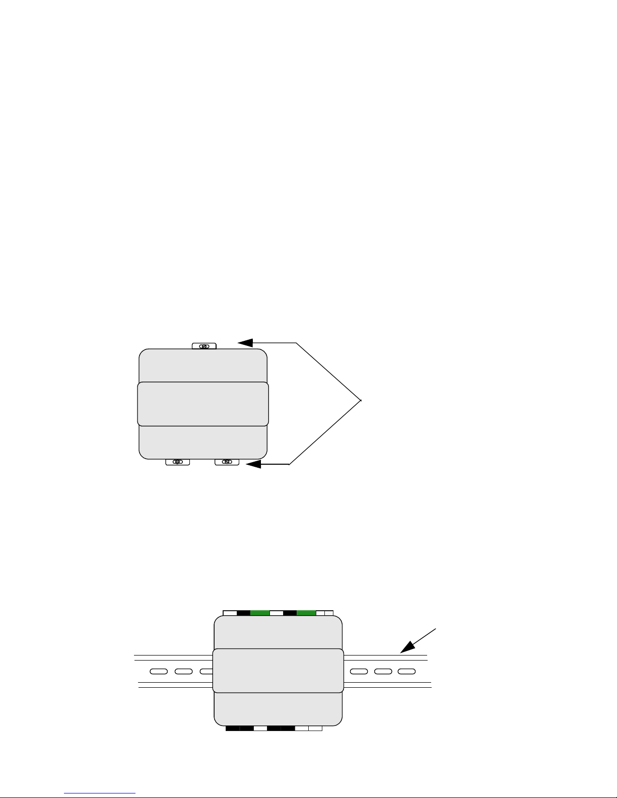
MOUNTING
You can mount the S321-IP controller on a flat surface, DIN rail, or in a
Johnson Controls’ approved enclosure (for example: S300-DIN).
For information on mounting the S321-IP in an enclosure, refer to the manual
provided with the enclosure.
To mount an S321-IP controller on a flat surface:
1. Fully extend the white clips located on the top and bottom of the
controller. You may need to remove the connectors.
2. Mount the controller to the surface with mounting screws.
3. Replace the connectors, if previously removed.
To mount an S321-IP controller on a DIN rail:
1. Fully extend the white clips located on the bottom of the controller.
You may need to remove the connectors.
2. Hook the controller on top of the rail and push in the clips.
Fully extended clips for
wall mount
(connectors are removed)
S321-IP
DIN rail
S321-IP
Page 7

S321-IP Network Controller Hardware Installation
24-10239-480 Rev. F
3
3. If you need to remove a controller from the DIN rail, reverse the
mounting sequence (pull down the bottom clips, then pull the bottom
of the controller out and lift it up.)
Power Source Requirements
Line Voltage Information
If the facility is located in an area where power lines are subject to
frequent lightning strikes, verify with the electric company that the
building transformer is equipped with surge protectors. These, as well as
a “crowbar” type of protection, can be installed at the main service
entrance if the building transformer is not equipped with lightning
protection.
While lightning is one cause of power line transients, others can be
internal or external to the building environment. The general application
of transient surge suppression is low-cost insurance to ensure long life of
the equipment being installed.
Lithium Battery
The S321-IP contains a lithium battery that is used for realtime clock
backup. The lithium battery is shipped from the factory charged and
operational.
If there are no power outages, change the battery every five years. If a
power outage occurs, the battery life is approximately 30 days. Replace
with Panasonic part number CR2025 or equivalent.
Parameter Value
Power 24 W
Input voltage +12 to +28 VDC; 16 to 28 VAC
Nominal voltage +12 to +24 VDC; 16 to 24 VAC
Current 1 A at 24 V; 2 A at 12 V
Class 2 transformer (optional) See step 8 on the Underwriters Laboratories Compliance
Verification Sheet at the beginning of this manual.
Page 8
S321-IP Network Controller Hardware Installation
24-10239-480 Rev. F
4
IMPORTANT: After you replace the lithium battery (recommended every five
years or after extended use), verify that the realtime clock is correct; otherwise,
you may need to adjust the time.
To replace the lithium battery:
1. Disconnect the 24 VDC power from the S321-IP.
2. Unscrew and open the plastic enclosure.
3. With a narrow (1/8 in.) blade, carefully pry up the battery until a
portion of the battery is out of the plastic holder.
4. With your free hand gently move the battery out of the holder while
keeping the battery pried up.
5. Dispose of the old battery according to local requirements.
6. Insert the new battery into holder.
IMPORTANT: The lithium battery is polarized. Ensure the side marked ‘+’ faces
out (that is, towards you).
7. Close the plastic enclosure and secure it with the screw.
8. Re-connect the power to the S321-IP.
CAUTION: Risk of Explosion.
Replace the battery with a lithium battery of the same type and
voltage rating. Dispose of the used battery in accordance with local,
national, and regional regulations. Failure to replace the battery with
one of the same type and voltage rating may result in an explosion
causing personal injury and property damage.
Page 9
S321-IP Network Controller Hardware Installation
24-10239-480 Rev. F
5
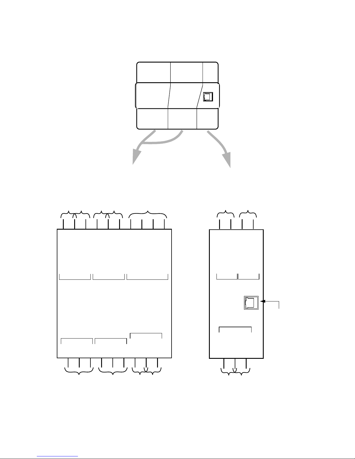
DESCRIPTION OF SIGNALS
READER n
COMNCNO
COMNCTAMP
COM
SPARE
PWR FAIL
COM
TAMP
NO
RDR n
STRIKE
RDR n
SHUNT
POWER RETURN
CAL RESISTOR
CAL RESISTOR
DATA1/Rs485+
DATA0/Rs485-
COM
POWER
GREEN LED
COM
RED LED
REX
COM
DOOR CONTACT
+12/24 VAC/VDC
RDR n
PANEL
RDR n RDR n RDR n
CAL POWER
RDR Request to
Exit Device
RDR Red Light
RDR Green Light
RDR Door
Reader
Calibration
Resistor
To the power
supply
RDR Door
Contact
RDR 1 General
Purpose Input 5
RDR 1 General
Purpose Input 6
RDR General
Purpose Input 3
RDR General
Purpose Input 4
RDR Shunt
RDR Strike
READER
1
RJ45
connector
READER
2
Page 10

S321-IP Network Controller Hardware Installation
24-10239-480 Rev. F
6
Wiegand Input
Description of Signals – DATA0 and DATA1 from each reader,
complying with the Wiegand interface specification.
Reference – These signals are referenced to logic ground (COM).
Protection – Each signal has a 6 V transient voltage suppressor between
it and COM.
Input Points
Description of Signals – The following are internally pulled up inputs:
The allowable voltage range for these signals is 0-12 VDC.
Reference – These signals are referenced to their associated COM input.
Protection – Each signal is protected with series resistors and dual
clamping diodes.
External Circuits – 4-state operation requires two external resistors and
switch circuit connected between an input point and COM. 2-state
operation requires an external switch connected between an input point
and COM. For wiring details see Wiring Input Devices on page 8.
Output Points
Description of Signals – The following are open collector outputs, with
voltage range for these signals of 0-24 VDC, limited to 50mA:
IMPORTANT: These open collector outputs can be damaged by alternating
current (AC) potentials as low as 1 VAC. Connect the LED outputs only to direct
current (DC) loads up to 24VDC.
• Reader 1 Door
Contact
• Reader 1 REX
•Reader 1 Tamper
• Reader 1 Spare
• Reader 2 Door
Contact
• Reader 2 REX
•Reader 2 Tamper
• Reader 2 Spare
• Power Panel Fail
• Panel Tamper
• Reader 1 Red LED
• Reader 1 Green LED
• Reader 2 Red LED
• Reader 2 Green LED
Page 11

S321-IP Network Controller Hardware Installation
24-10239-480 Rev. F
7
Reference – These signals are referenced to logic ground (COM).
Protection – Each signal has a 30 volt transient voltage suppressor
between it and system ground.
Relay Output Points
Description of Signals – NC, NO, and COM are the three connections to
a single pole, double throw relay. The following are the relay outputs:
Reference – The relay is a dry contact relay rated at 1 A at 24 VDC/
VAC, 25 VA maximum.
Reader Power
Description of Signals – 250 mA at 12 VDC is provided for each reader.
Protection – There is a 750 mA PTC re-settable fuse.
Network Connection
RJ45 connector – Use this connector to connect the S321-IP to the
network. The S321-IP communicates with the P2000 server via 10/
100Base-T Ethernet, using the TCP/IP protocol.
C
ABLE REQUIREMENTS
This table describes the recommended cable to use when wiring the S321-IP.
• Reader 1 Strike
• Reader 1 Shunt
• Reader 2 Strike
• Reader 2 Shunt
Description Recommended Cable Type Maximum Segment Length
S321-IP to Power
Supply
1
Listed, 18 AWG, hook-up
wire
Wire should fit within the enclosure.
S321-IP to Host Listed, Category 5, 24 AWG,
solid, 2 pair or 4 pair type.
354 ft (100 m). Cable, RJ45 connector,
and RJ45 crimp tool to be supplied by
customer.
Door Contact Belden 8442, 1 twisted,
unshielded pair, 22 AWG
500 ft. (152 m)
Door Strike and
Shunt
Belden 9740, 1 twisted,
unshielded pair, 18 AWG
Depends on power requirements of the
door strike. Do not reduce voltage to
the strike more than 10% over the 18
AWG wire, measured when energized.
Page 12

S321-IP Network Controller Hardware Installation
24-10239-480 Rev. F
8
Cable Routing
The cables should run in grounded conduit or at least 2 ft. (0.7 m) from
AC power, fluorescent lights, or other high energy sources.
IMPORTANT: Physically separate all data cables from power lines. If you use
conduit, do not run data cables in the same conduit as power cables or certain
door strike cables, for example, strike voltage greater that 42 V or Magnetic
door locks without EMI suppression.
All cables must conform with the following regulations: National
Electrical Code; NFPA 70; Local electrical codes; Canadian Electric
Code C22.1 (installations in Canada); BSI Standard BS7671, latest
edition (installations in Great Britain).
Make all cabling using good wiring practices and allow sufficient cable
length to allow service loops at cable terminations in the enclosure.
Wiring Input Devices
Tamper Switch Wiring
The tamper switch connects to a general purpose input point. To be
operational, the tamper switch must be wired to one of the unused input
points on any S321-IP in the enclosure and programmed.
Request to Exit Belden 8442, 1 twisted,
unshielded pair, 22 AWG
500 feet (152 m)
Reader Power
2
Belden 9740, 1 twisted,
unshielded pair, 18 AWG
Refer to reader manufacturer’s
specification for power requirements.
Reader Data0/
Data1
2
Belden 9744, 2 twisted,
unshielded pair, 22 AWG
500 ft. (152 m). Refer to reader
manufacturer’s specification for data
requirements.
Alarm Input Point Belden 8442, 1 twisted,
unshielded pair, 22 AWG to
each detector
500 feet (152 m)
1
When wiring more than one S321-IP, use the same type of hook-up wire and
communications wire to connect subsequent controllers.
2
Refer to reader manufacturer’s recommendations when using UL-listed readers. In the
absence of other recommendations, consider these cable specifications taking into
account the number of conductors that will actually be needed for installation.
Description Recommended Cable Type Maximum Segment Length
Page 13

S321-IP Network Controller Hardware Installation
24-10239-480 Rev. F
9
General Input Wiring
You can use the inputs as either 2-state or 4-state inputs. You must
calibrate the inputs depending on the needs of your site.
General Input Configuration
You have to configure an input before use.
The 2-state inputs, wired as shown under General Input Wiring on page 9,
must be uncalibrated. Execute an “Uncalibrate” command for each
2-state input.
The 4-state inputs, wired as shown under General Input Wiring on page 9,
must be calibrated. There are two methods available to calibrate a 4-state
input: “Calibrate” and “Calibrate with Resistor.”
• To use the Calibrate method, place the wired input in the secure state
and issue a “Calibrate” command. Use this method when the input
resistance tolerance is greater than 1% or unknown, when the cable
requirements (as described under Cable Requirements on page 7) are
not guaranteed, when the resistor value is less than 500 ohms, or when
all the inputs on an S321-IP are not wired with the same resistor
values.
• To use the Calibrate with Resistor method, install a resistor matching
the resistors wired to a 4-state input across the CAL RESISTOR
contacts, and issue a “Calibrate with Resistor” command. Use this
method when the input resistor tolerance is 1%, the cable
requirements (as described under Cable Requirements on page 7) are
guaranteed, and the resistor value is greater than 500 ohms. This
method allows an input to be calibrated before the input wiring is
completed. You can use this method to calibrate an input in any state
(alarm, secure, open, or short).
Note: The 4-state wiring requires two resistors of the same value. The
resistors can be 150-2000 Ohms, 1%, 1/4W. Recommended: 1200 Ohms.
e.g. DOOR
CONTACT
COM
e.g. DOOR
CONTACT
COM
e.g. DOOR
CONTACT
COM
2-state inputs
wiring
4-state inputs
wiring: N/O
4-state inputs
wiring: N/C
Page 14

S321-IP Network Controller Hardware Installation
24-10239-480 Rev. F
10
Ground
Every metal DIN enclosure in a Johnson Controls installation must have
its chassis bonded to a verified electrical ground (earth). Conduit ground,
cold water pipes, unbrazed joints or dissimilar metals are unacceptable
in the path of either building or supplemental ground. Where grounding is
required, connect only to the proven building electrical system ground
(earth).
B
ASIC COMMISSIONING
This section outlines the process of commissioning the S321-IP network
controller for use as a stand-alone device.
System Requirements
You need the following hardware and software to configure and operate
the S321-IP:
• Personal Computer (PC) with network connectivity running
Microsoft® Windows Server® 2008, Windows 8, Windows 7, or
Windows Vista®, 32 or 64-bit operating systems are supported
• Compatible web browser, such as Windows Internet Explorer®
Version 6.0 or higher, or Mozilla® Firefox® Version 1.0 or higher
For proper operation, cookies from the S321-IP must be allowed.
NOTE: Functionality of the browser’s Forward, Back, and Refresh buttons may
differ depending on the type of browser and the page being displayed.
Configuration Outline
Once the S321-IP and all peripheral devices are installed, you are ready to
configure the S321-IP using the controller’s embedded web interface.
Figure 1 shows a flowchart for configuring an S321-IP for use as a part of
the P2000 Security Management System (SMS). Figure 2 shows a
flowchart for configuring an S321-IP for use as a stand-alone device.
NOTE: To avoid network conflict caused by multiple controllers with the same
default name and static IP address, add and configure controllers one at a time.
Page 15

S321-IP Network Controller Hardware Installation
24-10239-480 Rev. F
11
Figure 1: S321-IP Basic Commissioning Flowchart: S321-IP with P2000 SMS
Mount, wire, and power the S321-IP
controller.
Does a DHCP
server exist on
the network?
Install the Lantronix® DeviceInstaller
software utility. Use this utility to
determine which IP address the DHCP
server assigned to the S321-IP.
Log on to the S321-IP user interface.
When logging on, use the IP address
assigned by the DHCP server or the
default controller name “s321ip”
(requires a DNS server on the network).
Log on to the S321-IP user interface
using the default static IP address of
192.168.0.1 or the default controller
name “s321ip” (when DNS service is
running).
Assign a static IP address, network
mask, and gateway to the S321-IP.
In systems with the DNS server,
assign a unique name to the controller.
Configure the following network
protocol settings, as needed: FTP,
SSL, and HTTP.
Define the P2000 host IP configuration
settings on the Configuration page
(Network menu).
Configure the S321-IP controller via the
P2000 software. Refer to the P2000
Software User Manual for instructions.
Note: Do not use local user interface to
configure the device.
You have completed the basic
commissioning of an S321-IP
controller.
Yes
No
Power off the S321-IP. Set DIP
switches #6 and #8 to ON (up). Power
on the S321-IP. Turn DIP switch #6 to
OFF (down).
Page 16

S321-IP Network Controller Hardware Installation
24-10239-480 Rev. F
12
Figure 2: Basic Commissioning Flowchart: Stand-alone S321-IP
Log on to the S321-IP user interface
using the default static IP address of
192.168.0.1 or the default controller
name “s321ip” (when DNS service is
running).
Assign a static IP address, network
mask, and gateway to the S321-IP.
In systems with the DNS server,
assign a unique name to the
controller.
Configure the following network
protocol settings, as needed: FTP,
SSL, and HTTP.
Set the current date and time at the
S321-IP controller.
Configure the S321-IP’s input/output
(I/O) point settings for two readers, one
reader with general purpose I/Os, or no
readers (all general purpose I/Os).
Add cardholder badges to the
database. If you use FTP, you can
import badge data from a spreadsheet
or from another panel. If you use the
badge enrollment feature, add names
to the cardholder records once the
badges are enrolled in the system.
Power off the S321-IP. Set DIP
switches #6 and #8 to ON (up). Power
on the S321-IP. Turn DIP switch #6 to
OFF (down).
Mount, wire, and power the S321-IP
controller.
Does a DHCP
server exist on
the network?
Install the Lantronix® DeviceInstaller
software utility. Use this utility to
determine which IP address the DHCP
server assigned to the S321-IP.
Log on to the S321-IP user interface.
When logging on, use the IP address
assigned by the DHCP server or the
default controller name “s321ip”
(requires a DNS server on the network).
You have completed the basic
commissioning of an S321-IP
controller.
Yes
No
Page 17

S321-IP Network Controller Hardware Installation
24-10239-480 Rev. F
13
DIP Switch Settings
The DIP switches are accessible through the front panel of the S321-IP.
The settings should be adjusted as follows (make sure you power cycle
the controller after you change any switch settings):
Figure 3: DIP Switch Settings
Determining the Controller’s IP Address on a DHCP-enabled Network
DHCP is a network protocol that automatically assigns IP addresses to
devices on a TCP/IP network. S321-IP controllers can be connected to a
DHCP network to receive their dynamic IP addresses.
If the S321-IP is connected to a DHCP network, use the Lantronix®
DeviceInstaller software utility provided on the S321-IP Network
Controller CD to determine the IP address the DHCP server assigned to
the controller.
Before determining the IP address:
1. Find out the controller’s Media Access Control (MAC) address. It is
listed on the sticker on the left side as well as top of the S321-IP. You
need to match the MAC address to the Hardware Address listed on the
utility’s user interface.
2. If needed, adjust the DIP settings for DHCP. See Figure 3 for details.
ON
1
2
3 4
5 6 7
8
For DHCP:
Switches #6 and
#8 down (OFF)
ON
1
2
3 4
5 6 7
8
ON
1 2
3 4
5 6 7
8
For Static IP:
Switch #6 down
(OFF) and switch #8
up (ON)
For Static IP
Commissioning:
Switches #6 and #8
up (ON)
ON
ONON
Note: Switch #1 must
always be up (ON)
Page 18

S321-IP Network Controller Hardware Installation
24-10239-480 Rev. F
14
To determine the IP address assigned to the S321-IP by the DHCP
server:
1. Insert the S321-IP Network Controller CD into the computer that will
run the utility.
NOTE: The S321-IP and the computer that will run the DeviceInstaller utility
must be connected to the same network interface.
2. Install the DeviceInstaller utility.
3. From the Windows taskbar, select Start>All Programs (or
Programs)>Lantronix>DeviceInstaller>DeviceInstaller to launch
the DeviceInstaller software utility.
4. When DeviceInstaller launches, the utility automatically searches for
all S321-IP controllers on the network and lists them in the right pane.
5. Locate the S321-IP controller’s MAC address under the Hardware
Address column.
6. Once you locate a match, use the IP address assigned to the controller
when logging on to the S321-IP controller’s user interface.
Page 19

S321-IP Network Controller Hardware Installation
24-10239-480 Rev. F
15
Configuring and Using a Static IP Address
Use the static IP address if the S321-IP is not connected to a DHCPenabled network.
To use a Static IP Address:
1. With the S321-IP unit powered off, adjust the DIP settings for Static
IP commissioning as follows: turn switch #6 and switch #8 up (ON).
2. Power on the unit.
3. Adjust the DIP settings for Static IP use as follows: turn switch #6
down (OFF).
4. Log on to S321-IP (see Logging On and Off).
5. Assign a new static IP address to the controller using the S321-IP user
interface. (Log in and go to Network>IP. On the IP page configure
the IP address under the Static IP Configuration section. Refer to the
S321-IP Network Controller Configuration and Operation Manual
for more information.)
6. The controller reboots automatically. The new settings will take effect
after the reboot.
Logging On and Off
You can log on to the user interface using the S321-IP controller’s current
IP address or name (in networks with the DNS server).
Page 20

S321-IP Network Controller Hardware Installation
24-10239-480 Rev. F
16
To log on to the S321-IP controller’s user interface:
1. From a web browser, enter the following URL, using either the IP
address or name of the S321-IP:
http://name (the default name is s321ip), or
http://IP Address (the default static IP address is 192.168.0.1),
2. Enter your User Name and Password. Your user name and password
are defined on the HTTP configuration page.
If accessing the S321-IP user interface for the first time, enter
the following in the exact letter case, as shown:
User Name: admin
Password: PASS
NOTE: If you cannot successfully log on to the S321-IP user interface, consult
with the Network Administrator for assistance.
3. Click OK. The Main menu options appear.
To log off from the S321-IP controller’s user interface:
1. To log off from the S321-IP user interface, click the Logout link at
the upper-right corner of any page or simply close the browser
window.
In addition, the S321-IP user interface automatically logs off
the current user if the system does not detect any activity for
20 minutes.
T
HE S321-IP USER INTERFACE
This section briefly describes the S321-IP user interface, which consists of:
Menu Bar – Each menu item on this bar reveals a different set of menu
options, which enable you to perform specific functions, such as configuring,
monitoring, or operating the S321-IP.
Menu Options – These options are a collection of functions associated with
the menu selected on the Menu bar. To select a menu option, simply click the
text link or the graphic icon next to it, if applicable (not all menu options have
an associated icon).
Page 21

S321-IP Network Controller Hardware Installation
24-10239-480 Rev. F
17
Logout Link – Click to log out of the S321-IP user interface.
See the diagram below for the Main menu navigation map:
Menu Bar
Menu
Options
Logout Link
Commands
System
Info
Alarms and
Events
Main Database Network
Reboot
System
Firmware
Upgrade
Database
Operations
Logger
Operations
Output
Operations
Input
Operations
Reader/
Keypad
Operations
Badge Count
Logger Record
Count
ACM Firmware
Version
NIM Firmware
Version
Reader Info
Output Info
Schedule
Info
Input Info
Page 22

S321-IP Network Controller Hardware Installation
24-10239-480 Rev. F
18
See the diagram below for the Database menu navigation map:
Report Strike/
Reader Status
Security Level
Access and
Shunt Time
Anti Passback
Assign
Schedules
Badge ID/PIN
Badge/Reader
Override
AUX Access
Reader
Enabled
Badge Types
Name/Index
Suppression
Schedule
Daylight
Savings
Time/Date
Configuration
Report Status
Input and
Latch Enable
Name/Index
Name/Index
Flash Period
Duration
Report Status
Output Enable
Name/Index
Schedule
Enable
Define Days/
Times
Name/Index
Holiday Enable
Typ e
Month/Day/
Year
Storage Time
Last/First
Name
Badge Number
Facility Code
Assign
Schedules
Last/First
Name
Security
Level
PIN
Override
Status
Schedule
Config
Holiday
Config
Logger
Config
Badge
Config
View
Badge(s)
Main Database Network
Time/Date
Config
RDR/Keypad
Config
Input
Config
Output
Config
Debounce Time
Output Point
Link
Page 23

S321-IP Network Controller Hardware Installation
24-10239-480 Rev. F
19
See the diagram below for the Network menu navigation map:
T
ECHNICAL SPECIFICATIONS
The terminal is expected to operate at moderate temperature variation, noncondensing humidity variation, moderate vibration, and possible dust
contamination.
Item Specification
Input Power +12 to +24 VDC or 16 to 24 VAC at 24W
Reader Interface • 2-wire Wiegand (up to 256 bits)
• 12 VDC, 250 mA (typical), 500 mA (peak)
• Red indicator
• Green indicator
General Purpose Inputs Resistive load
Relay Outputs 1 A max. 0-24 VDC/VAC, 25 VA max
Red LED/Green LED
Outputs
50 mA max. 0-24 VDC.
These open collector outputs can be damaged by alternating
current (AC) potentials as low as 1 VAC. Connect the LED
outputs only to direct current (DC) loads up to 24VDC.
Communications 10/100 Base-T Ethernet using TCP/IP protocol
Certifications • FCC, Class B
•CE Mark
•C-Tick
SNMP Agent
Enable
System
Information
Community
Traps
Configuration
FTP Enable
Certificate
Private Key
Self-Signed
Certificate
IP
SNMP FTP SSL HTTP
Main Database Network
Username
and Password
Timeout
Maximum Bytes
Allowed
Admin Account
User Account
DHCP Enable
IP Address
Network Mask
Gateway
MAC Address
P2000 Host
Name
User Name
or IP
Name
P2000 Host
IP Address
Page 24

S321-IP Network Controller Hardware Installation
24-10239-480 Rev. F
20
MAINTENANCE
This section provides maintenance instructions, operational testing procedures,
and information on replacement parts.
LEDs
The S321-IP controller has 6 LEDs:
• Power (Power): On during normal operation.
• Status (STATUS): Blinks every second when unit is operational.
• Transmit (XMIT) and Receive (RCV): Indicate internal controller
activity
• Link (LINK): On when there is valid physical network connection
• Active (ACT): On during active network communication to and from
the controller.
LINK and ACT are located near the RJ45 connector.
Routine Maintenance
Perform the following routine maintenance on the S321-IP:
1. Periodically check the continuity of the grounding circuit.
2. Perform operational testing monthly (see Testing Procedure on
page 21).
3. Change the battery every five years. Replace with Panasonic part
number CR2025 or equivalent.
Mounting Specifications DIN rail
Flat surface
Dimensions 5.7 H x 5.9 W x 2.2 D inches
(14.4 cm x 15.0 cm x 5.5 cm)
Ambient Temperature 32º to 122º F (0º to 50ºC)
Humidity 10 to 85% non-condensing
Ventilation Cabinets require free movement of air over all exposed
surfaces
Item Specification
Page 25

S321-IP Network Controller Hardware Installation
24-10239-480 Rev. F
21
Impaired Performance Conditions
Testing Procedure
To check for proper operation of the S321-IP controller:
1. Verify that the “Power” LED is ON.
2. Verify that the “STATUS” LED flashes once per second.
3. Verify that the “XMIT” and “RCV” LEDs blink.
4. If the controller is connected to the network, verify that the “LINK
LED” is on.
5. Present a valid card to each reader connected to the S321-IP reader
interface and then verify that access is granted (green lamp lights).
6. Present an invalid card to each reader connected to the S321-IP reader
interface and then verify that access is denied (red lamp lights).
Replacement Parts
There are no serviceable components inside the S321-IP plastic
enclosure. Generic replacement terminal blocks can be ordered if lost.
For more information on the parts listed, refer to the applicable catalog
page.
Fuses
The S321-IP has no replaceable fuses.
Condition Information Location
Unit environment not as specified. Basic Commissioning on page 10.
Unit power and grounding not as
specified.
Power Source Requirements on page 3, General
Input Configuration on page 9.
Cable length or type not as specified. Cable Requirements on page 7.
Backup battery not replaced correctly. Lithium Battery on page 3.
Page 26

S321-IP Network Controller Hardware Installation
24-10239-480 Rev. F
22
Page 27

We welcome your comments at BE-techpubs-security@jci.com.
Security Solutions
(805) 522-5555
www.johnsoncontrols.com
 Loading...