

Page 1

Application Note
Issue Date April 20, 2012
Connecting Serial Controllers to the P2000 Comark
Server Running Software Version 3.11
This document describes how to connect supported serial controllers to the P2000 Comark
server running software Version 3.11. P2000 supports the following serial controllers:
• S321-DIN
• D620
• D600-AP (Version PS 155B or higher)
• D620-TIU
• S320
• P900
If installing serial controllers, you may need the following equipment:
• Digi® AccelePort® serial adapter board (installed at the P2000 server)
• PC232 converter (S321-DIN and P900 controllers excluded)
• B&B Electronics RS-232 to RS-485 converter (model 485OT9L) (S321-DIN controllers
using serial communications only)
Note: The S321-DIN can use serial communications with the RS-232 to RS-485 converter,
or it can communicate via IP using the Digi One® SP converter. This document covers both
scenarios.
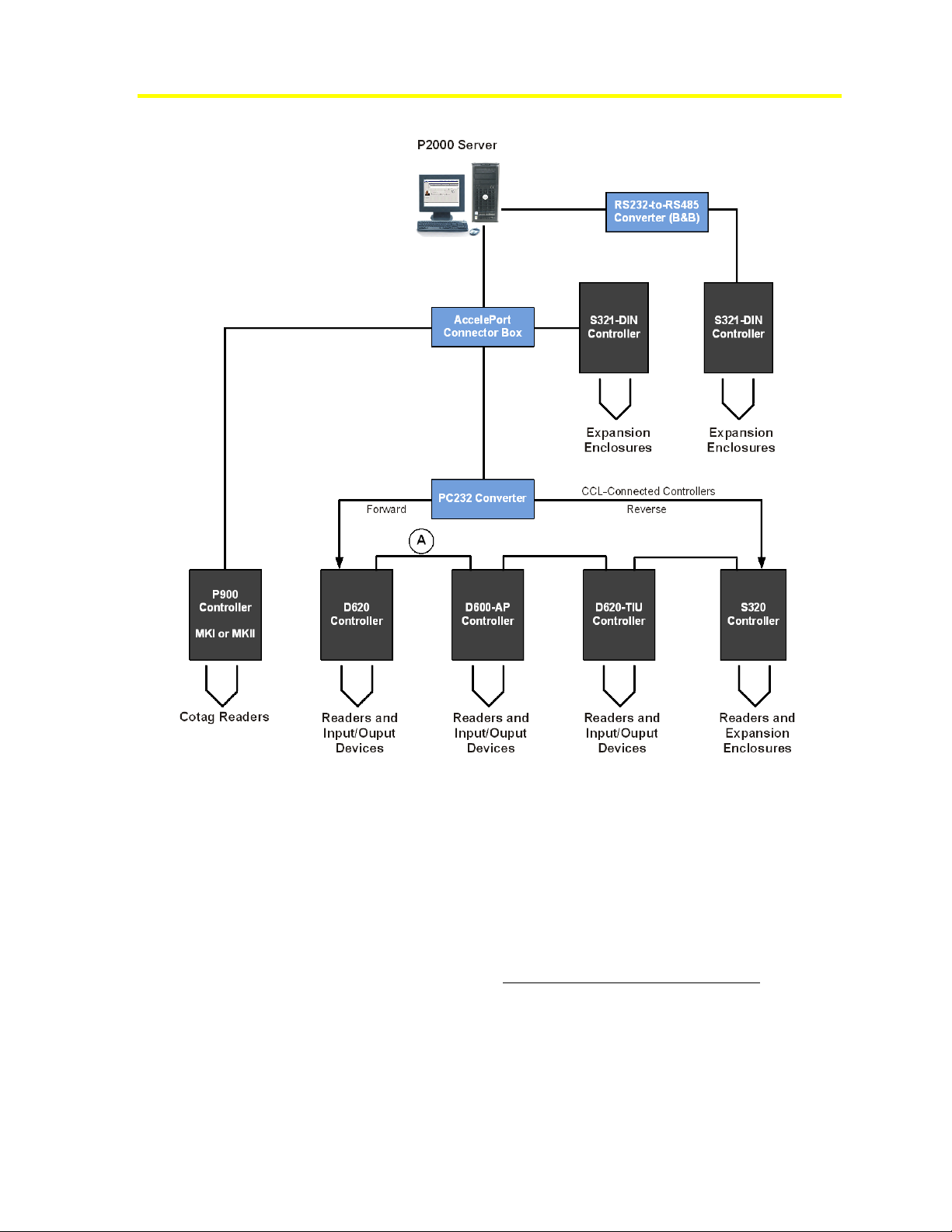
P2000 supports a controller loop configuration in which most serial controllers connect to the
server using a PC232 converter and an AccelePort connector box. See Figure 1 for an
illustration of a P2000 system component configuration with serial controllers.
© 2012 Johnson Controls, Inc. www.johnsoncontrols.com
Code No. LIT-12011743 P2000 Software Release 3.11
Page 2
2
Connecting Serial Controllers to the P2000 Comark Server Running Software Version 3.11
Figure 1: P2000 System with Serial Controllers
Connecting Serial Controllers
The following sections describe the hardware components needed to support serial
controllers (D620, D620-TIU, D600-AP, S320, and P900), including how to connect the
controllers to the system and establish communications. These components are not supplied
and must be purchased separately.
Note: This section does not include instructions for installing S321-DIN controllers. For
information on connecting these controllers, see Connecting S321-DIN Controllers on
page 13.
Note: The sections on the current loop converter do not apply to the P900 controller. For
more information on the P900 controller, refer to the P900 Installation Manual (Part No.
09-9133-01).
Preliminary – This information may change.
Page 3
Connecting Serial Controllers to the P2000 Comark Server Running Software Version 3.11
Digi PORTS/16m
Xem PCI Adapter
Installed in PCI Slot 2
DB-44 Cable
Front Side
Back Side
PC-232
Converter
Legacy
Controller
(S321/P900
Excluded)
DB-25 Female Connector
RJ-45
Connector
EBI OUT
EBI IN
Side
Panel
Connect to EBI IN
DB-25 Male Connector
Acceleport to
PC-232
To next legacy
controller
Each channel supports 16
legacy controllers
P900
Controller
To next P900 controller
For detailed information about configuring controller loop communication, refer to the
installation documentation of the serial controller.
Installing the AccelePort Serial Adapter
The AccelePort board is an expandable serial communication adapter that provides each
server with additional connections to serial controllers (S321-DIN controllers excluded).
Install the AccelePort board in one of the available PCI slots. After installing the AccelePort
board, connect the cable to the board’s interface. Follow the manufacturer’s documentation
for detailed instructions on installing the board.
Note: When configuring the AccelePort, name your devices as COM1, COM2, and so on.
The AccelePort does not support other names.
AccelePort to PC232 Installation
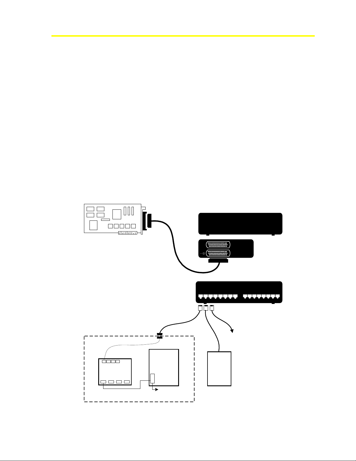
The AccelePort module provides additional RS-232 serial ports. The module is connected to
the AccelePort PCI board in the server by a DB44 RS-232 cable. Connect one end of the
DB44 cable to the AccelePort COM port, and the other DB44 end to the CPU port on the
module. See Figure 2.
3
Preliminary – This information may change.
Figure 2: AccelePort Connection (16 port model shown)
Page 4

4
Connecting Serial Controllers to the P2000 Comark Server Running Software Version 3.11
Current Loop Converter
The D620, D620-TIU, D600-AP (Version PS 155B or higher), and S320 controllers
communicate with the system via the Johnson Controls® proprietary Nodal Protocol B. The
current loop converter converts standard serial communication to Nodal Protocol B to allow
the P2000 Database Server to communicate with these controllers.
Current loop converters are available in two models:
• Model PC232-S4-1 Accommodates 4 loops and operates on 120 VAC
• Model PC232-S4-2 Accommodates 4 loops and operates on 240 VAC
Both models use the same type of enclosure for mounting. If installing only one 4-loop
converter, communication can be established with up to 64 controllers. If installing two
4-loop converters, communication can be established with up to 128 controllers. The
enclosure contains a tamper switch, transformer, EMI line filter, and current loop converter
Printed Circuit Board (PCB).
Specifications
The environmental specifications for the Field Panel Interface board are the same as for the
computers. The specifications of the current loop converter are listed in Table 1.
Table 1: Current Loop Converter Specifications
Item Specification
Number of Channels per PCBA
Input/Output
Number of Serial Controllers per Channel
Ambient Temperature
Relative Humidity
Ventilation
Power Requirements:
PC232-S4-1
PC232-S4-2
4
RS-232 to current loop and current loop to RS-232
16
32° to 122°F (0° to 50°C)
0 to 95%
Free flow of air over all exposed surfaces
120 VAC, 125 milliamps
240 VAC, 70 milliamps
PC232-S4-X Converter Installation
Install the PC232-S4-X enclosure on a wall or other mounting surface in a restricted-access
area with an ambient temperature between 32° and 122°F (0° and 50°C) and a relative
humidity between 0 and 95 percent.
Note: High heat and humidity can be harmful to electronic equipment and contributes to
early component failure. Long life and reliable operation can best be obtained by installing
the converter in an environment which is comfortable to a person.
Suggested installation locations include a locking utility closet, a crawl space, or inside a
suspended ceiling (if necessary). Install the unit so the door can swing fully open to the right.
The location must allow free flow of air over all exposed surfaces.
Preliminary – This information may change.
Page 5

Connecting Serial Controllers to the P2000 Comark Server Running Software Version 3.11
The converter can function in any position, but we recommend mounting it flat against a wall
with the hinge to the right.
To be UL-compliant, the Current Loop Converter must be located in the same room and
within 20 feet (6.1 m) of the Proprietary Station.
Installing the Enclosure
To meet UL requirements, the PC232-S4-X board must be installed in the enclosure supplied
for the PC232-S4-X. This enclosure has four corner holes for mounting (see Figure 3). The
diameter of these holes is 0.196 inches (4.98 mm).
The enclosure has knockout holes for cable entry. You can bring cables to the mounting
location and terminate them before or after the enclosure installation, as dictated by the
requirements of the installation.
To install the enclosure:
1. Remove the PC232-S4-X board from the enclosure by disconnecting the power cable
from J6 and the tamper switch cable from J1. Then, remove the four screws securing the
PC232-S4-X board to the enclosure.
5
2. Set aside the screws in a safe place, so you can use them to replace the board into the
enclosure.
3. Hold the enclosure in the desired location on the mounting surface and use as a template
to mark the location of the four mounting holes that correspond to the holes shown in
Figure 3.
4. Bore holes in the mounting surface at the four marks. If necessary, install hollow-wall
anchors.
5. Mount the enclosure on the wall using appropriate hardware.
6. Bring the cables to the mounting location, allowing enough excess cable for a service
loop.
7. Determine the point of entry for each cable and remove the appropriate knockout(s).
8. When using conduit, attach appropriate conduit fasteners to the conduit in the enclosure.
9. Install the PC232-S4-X board removed in Step 1.
10. Reconnect the power cable to J6 and the tamper switch cable to J1. You have completed
the enclosure installation.
Preliminary – This information may change.
Page 6

6
Connecting Serial Controllers to the P2000 Comark Server Running Software Version 3.11
Figure 3: PC232 4X Mounting Holes Location
Cabling from PC232-S4-X
All cabling must be in conformance with the National Electric Code, NFPA 70*. Observe all
local codes for specific wiring and conduit requirements. Construct cabling using good
wiring practices. All cables should be long enough to allow for service loops at their
terminations within the terminal enclosure. This allows the installer to conveniently wire the
cable connectors and plug them into the mating connectors.
* For Canadian installations, refer to the Canadian Electric Code, C22.1.
Take into account the following requirements for cable routing:
• Route power lines separately from data lines. These lines can be a standard
3-wire stranded #16 AWG UL listed/CSA approved line cord used with UL listed/CSA
approved strain relief.
• All low-level input cables (system data, alarm cables, etc.) must be shielded types and
should be in grounded conduit or at least two feet from AC power, fluorescent lights, or
other high-energy sources.
Table 2 lists the connectors in the kit supplied with one PC232-S4-X current loop converter,
and Table 3 lists the connectors supplied with two PC232-S4-X converters. Use these
connectors to construct the cables.
Preliminary – This information may change.
Page 7

Connecting Serial Controllers to the P2000 Comark Server Running Software Version 3.11
One PC232-S4-X Unit
This kit is used for the installation of one PC232-S4-X board. The cable connections of the
kit complete the interface of the serial controllers to the server.
Table 2: Connector Kit (supplied with one PC232-S4-X unit)
Type Quantity Mating Connector/Function
7
Conn., 25-pin, MTA-100
DB-25 Backshell
Conn., 2-pin, MTA-100
Conn., 4-pin, MTA-100
Conn., 5-pin, MTA-100
Conn., 8-pin, MTA-100
Screw, 6-32x7/8 inch
Screw, 6-32x1/2 inch
4 Ports 1, 2, 3, and 4 on connector box
4 Covers for DB-25 connectors
1 J1 to tamper switch connector on current loop converter board
3 J3, J4, J5 on first or only current loop converter board
1 J2 on first current loop converter board
4 J7, J8, J9, J10 on first or only current loop converter board. (The
other sides of the cables made with these connectors plug into
the serial controllers.)
4 Used to mount current loop converter board to enclosure wall
6 Used to ground wire shields to enclosure wall
Two PC232-S4-X Units
This kit is used for the installation of two PC232-S4-X boards. The cable connections of the
kit complete the interface of the serial controllers to the server.
Table 3: Connector Kit (supplied with two PC232-S4-X units)
Type Quantity Mating Connector/Function
Conn., 25-pin, MTA-100
DB-25 Backshell
8 Ports 1 through 8 on connector box
8 Covers for DB-25 connectors
Conn., 2-pin, MTA-100
Conn., 4-pin, MTA-100
Conn., 5-pin, MTA-100
Conn., 8-pin, MTA-100
Screw, 6-32x7/8 inch
Screw, 6-32x1/2 inch
2 J1 to tamper switch connector on current loop converter board
6 J3, J4, J5 on both current loop converter boards
2 J2 on both current loop converter boards
8 J7, J8, J9, J10 on both current loop converter boards (The other
sides of the cables made with these connectors plug into the
serial controllers.)
8 Used to mount current loop converter board to enclosure
12 Used to ground wire shields to enclosure wall
The connectors supplied are mass termination type; attaching the cable wires to the
connectors requires special tools. The recommended tools are listed in Table 4.
Preliminary – This information may change.
Page 8

8
Connecting Serial Controllers to the P2000 Comark Server Running Software Version 3.11
Table 4: Tools Required to Install Wires in MTA Connectors
Johnson Controls
Part Number
96-0014
96-0015
96-0010-01
AMP Part
Number
58074-1 Pistol-grip Handle Assembly
58246-1 MTA-100 Modular Head (used in pistol-grip tool)
59803-1 MTA-100 Maintenance Hand Tool (inserts one wire at a time)
Tool Description
Cabling between PC232-S4-X Converter Board and Connector Box
Create the cables to connect the connector box and the PC232-S4-X converter board using
#22, 4- and 5-conductor shielded cabling. We recommend Belden® 9940 and 9941,
respectively. The cable length must not exceed 25 feet (7.6 m).
For systems with one PC232-S4-X converter board, use 4-conductor cable to connect ports 2,
3, and 4 of the FPI connector box to the PC232-S4-X PCB connectors J3, J4, and J5,
respectively. Use the 25-pin connectors supplied with the kit on ports 2, 3, and 4 of the
connector box. Use the red 4-pin connectors supplied with the kit on the PC232-S4-X PCB
end. A 5-conductor cable connects port 1 of the connector box to connector J2 on the PC232S4-X PCB. Use the remaining 25-pin connector for port 1 of the connector box and the only
red 5-pin connector for J2 of the PC232-S4-X PCB. (See Figure 4 for the wiring diagram.)
For systems with two PC232-S4-X converter boards, use 4-conductor cable to connect ports
2 through 8 of the FPI connector box to both PC232-S4-X PCB connectors J3, J4, and J5,
respectively. Use the 25-pin connectors supplied with the kit on ports 2 through 8 of the
connector box. Use the red 4-pin connectors supplied with the kit on both PC232-S4-X PCB
ends. Use a red 5-pin connector for connector J2 on the second PC232-S4-X PCB. Only four
wires connect to the 5-pin connector attaching to J2 of the second PC232-S4-X PCB. A
5-conductor cable connects port 1 of the connector box to connector J2 on the first PC232S4-X PCB. Use the remaining 25-pin connector for port 1 of the connector box and
remaining red 5-pin connector for J2 of the first PC232-S4-X PCB. (See Figure 4 for the
wiring diagram.)
Cabling between PC232-S4-X and the Serial Controllers
Construct the cables to connect the PC232-S4-X and the serial controllers using #22, two
twisted pair cabling (Belden 8723 recommended). See Figure 4 for the wiring diagram. The
diagram shows the pin-to-pin connections for the serial controllers. The maximum cable
length is 4,000 feet (1,219 m) total loop distance.
Install a Lightning Transient Suppressor at each end of every cable between the PC232-S4-X
and the serial controller that is exposed to an area where lightning may strike directly or
nearby. This includes any above-ground cable runs between buildings. We recommend the
Johnson Controls Model TS10/TS11 Transient Suppressor for this purpose.
Preliminary – This information may change.
Page 9

Connecting Serial Controllers to the P2000 Comark Server Running Software Version 3.11
Tamper Switch
Install the wires in the cable from the tamper switch into the two-pin connector provided in
the connector kit, and plug the connector into J1 of the first or only PC232-S4-X converter
board. If using two PC232-S4-X units, only a single tamper switch connection is needed.
Fuses
The fuse located in the PC232-S4-X PCBs is 1 A, 3AG, SloBlo (Littelfuse® PN 313001).
Current Loop Converter, Routine Maintenance
• Vacuum the current loop converter every six months, or more often if the unit is located
in a dusty environment.
• Check the continuity of the grounding circuit periodically.
Testing Communications
This test assumes that all hardware and software is installed. (Refer to the P2000
Server/Workstation Software Installation Manual [Part No. 24-10618-120] for instructions.)
Monitor the status of loops, controllers, and terminals by using the P2000 System Status
window (located in the System menu). Refer to the P2000 Software User Manual (Part No.
24-10618-147) for more information.
9
Use visual checks to help verify that the system is working properly. Use the two wiring
diagrams, in Figure 4 and Figure 5, as troubleshooting aids.
• LED2 through LED9 on the PC232 PCB flicker when operating correctly.
• If the LEDs on the PC232 PCB do not flicker, verify that all cables are constructed
correctly and securely attached.
• If LED1 is lit, the board is receiving power. If not, verify power is flowing from the main
source to the PC232.
Preliminary – This information may change.
Page 10

10
Connecting Serial Controllers to the P2000 Comark Server Running Software Version 3.11
Figure 4: Interconnect: I/O Converter to Current Loop Converter
Preliminary – This information may change.
Page 11

Connecting Serial Controllers to the P2000 Comark Server Running Software Version 3.11
11
Figure 5: Current Loop Converter to Terminal Controller
Grounding and Connectors
This section provides instructions for grounding cable shields for data and low voltage
installations. Follow these guidelines for electromagnetic compatibility (EMC) conformity
and improved system reliability.
• Every unit in a Johnson Controls system’s installation must have its chassis connected to
a verified electrical ground (earth). In all cases, the pertinent national wiring codes apply.
• National Electrical Code NFPA 70 must be followed for installations in the USA.
• Canadian Electrical Code C22.1 must be followed for installations in Canada.
• BSI Standard BS7671 (latest edition) must be followed for installations in Great Britain.
Additional information is given in the Johnson Controls Installer’s Code of Practice
(FAN 1196).
Important: Conduit ground, cold water pipes, unbrazed joints, and dissimilar metals are
unacceptable in the path of either building or supplemental ground. Where grounding is
required, connect only to the proven building electrical system ground (earth).
Preliminary – This information may change.
Page 12

12
Connecting Serial Controllers to the P2000 Comark Server Running Software Version 3.11
Data and Low Voltage Installations
The following sections describe recommended grounding of D-type connectors and
grounding requirements in the U.S.A. and Europe. The following notes apply to all
installations described in the Grounding and Connectors section and subsections.
1. Strip back the outer cover of the cable to reveal the cable’s screen.
2. Cut back the screen so it just enters the enclosure.
Connect cable screens at both ends when connecting cables to user peripherals (such as
printers).
3. The drain wire that extends from the screen-type shield must be kept as short as possible
(typically 2.5 cm or 1 inch). Connect a lug to the end of the wire and screw securely to
the wall of the enclosure or the nearest stud.
4. All internal ground (earth) bonding straps must be left intact after installation.
5. Check that grounding points are clean and free from paint or corrosion.
D-Type Connectors
All D-type connectors must use an Electromagnetic Interference (EMI) shielded shroud.
Verify good contact occurs when connecting D-type connector shrouds to cable shields.
Figure 6 shows a critical contact throughout the 360 degrees of the cable’s screen at the point
of entry to the shell. To ensure a good fit, strip the cable’s outside layer back to reveal the
metal shield and extend the shield to the very edge of the metal shroud’s connector. If the
shield does not fit snugly, apply metallic tape to ensure a firm contact.
The two curved parts of the shroud are shown in Figure 6 making contact with the flat plate
of the shroud. Tighten the two remaining screws to ensure a firm fit.
Preliminary – This information may change.
Page 13

Connecting Serial Controllers to the P2000 Comark Server Running Software Version 3.11
Figure 6: Example of D-Type Connector Grounding
13
Connecting S321-DIN Controllers
The S321-DIN controller provides interface control for access and security devices
associated with a door. The key features of the S321-DIN include:
• Support for RS-485 bus communications at 4800, 9600, 19,200, or 38,400 (default) (auto
baud rate detection at the controller)
• Improved RS-485 bus polling algorithm
• Two-door access control input/output interface
• One general-purpose input and output per terminal
The S321-DIN can communicate with the P2000 server in one of the following
configurations:
• Serial communications using a B&B Electronics RS-232 to RS-485 converter (model
485OT9L)
• IP network communications using the Digi One SP serial-to-Ethernet converter
The following subsections provide instructions for installing the previous converters. For
additional instructions on installing and configuring the S321-DIN controller, refer to its
documentation.
For TCP/IP networking information associated with the P2000 system, refer to the P2000
Comark Server Hardware Installation Instructions (Part No. 24-10618-112).
Preliminary – This information may change.
Page 14

14
Connecting Serial Controllers to the P2000 Comark Server Running Software Version 3.11
Serial Installation with the B&B Electronics RS-232 to RS-485 (Model 485OT9L)
Converter
This device converts RS-232 signals to RS-485 signals and must be used when installing an
S321-DIN controller in a serial configuration.
To install the converter:
1. Change the switch settings on the converter to match the baud rate of the host computer.
See Table 5.
Table 5: Baud Rate Selection
Baud Switch 1 Switch 2 Switch 3 Switch 4 R21 Time out (ms)
1200
2400
4800 ON
96001
19,200
38,400
1. Default setting
OFF OFF OFF OFF 820k Ω 9.0
OFF OFF OFF OFF 410k Ω 4.5
OFF OFF OFF Not Used 2.2
OFF
OFF OFF
OFF OFF OFF
ON
OFF OFF Not Used 1.1
ON
OFF Not Used 0.6
ON
Not Used 0.3
2. Set the remaining switch positions for RS-485 Half-Duplex operation and termination
according to Table 6.
Table 6: Remaining Switch Settings
Switch 5 Switch 6 Switch 7 Switch 8
ON ON ON
OFF
3. Ensure JP1 is on SD pins.
4. Using Belden 5341FE (18 AWG, shielded, 2 twisted pair) or equivalent cable, wire the
pins from the S321-DIN serial port to the converter’s terminal block according to Figure 7.
Figure 7: RS-232 to RS-485 Converter Connections
Preliminary – This information may change.
Page 15

Connecting Serial Controllers to the P2000 Comark Server Running Software Version 3.11
15
Network Installation with the Digi One SP Converter
The Digi One SP device enables an S321-DIN controller to connect to an IP network via the
controller’s serial port. See Figure 8.
Figure 8: S321-DIN Controller in an IP Network Configuration
To install the converter:
1. Change the DIP switch settings on the bottom of the Digi One SP converter according to
Figure 9 and Table 7.
Figure 9: Digi One SP Converter DIP Switch Settings
Table 7: Digi One SP Converter DIP Switch Positions
DIP Switch Position
1
2
Down/OFF
Down/OFF
3 Up/ON
4
Preliminary – This information may change.
Down/OFF
Page 16

16
Connecting Serial Controllers to the P2000 Comark Server Running Software Version 3.11
2. Using Belden 9773 (18 AWG, shielded, 3 twisted pair) or equivalent cable, wire the pins
from the S321-DIN serial port to a DB-9F connector according to Figure 10 and Table 8.
Figure 10: Digi One SP Connections
Table 8: Digi One SP DB-9F Connections
S321-DIN Wiring Base DB-9F Connector
+RS485
-RS485
REF
PIN 2
PIN 3
PIN 6
PIN 9
PIN 5
3. Connect the DB-9F connector to the Digi One SP’s DB-9M connector.
4. Run an Ethernet cable from the Digi One SP to your network connection.
5. Connect the power cable to the Digi One SP and run to an appropriate 110/240 VAC
power source.
To install the driver for the Digi One SP and configure the device, download the driver and
configure the software according to the screen captures located at:
ftp://cardkey:cardkey2000@ftp2.johnsoncontrols.com/cardkey-out/S321/DigiOneSP%20(Working%20Driver)/
Important: Do not install the driver provided with the Digi One SP or on the Digi Web site.
Use only the driver provided on the Johnson Controls File Transfer Protocol (FTP) site.
Preliminary – This information may change.
 Loading...