

Johnson Controls RLY13A-600R, RLY13A-602R, RLY13A-603R, RLY13A-608R, RLY13A-609R Series Manual
...Page 1
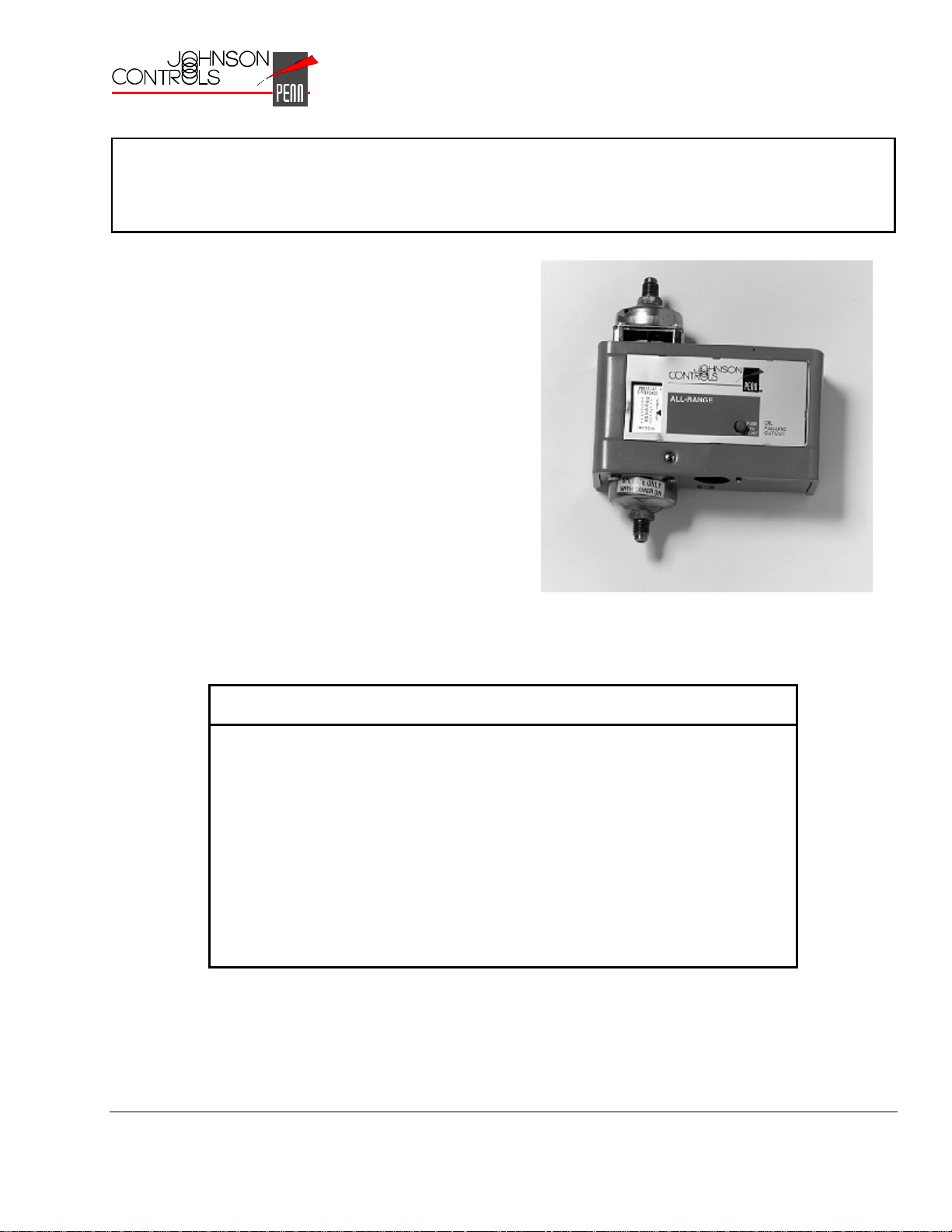
P28 and P128 Series Lube Oil Controls
with Built-in Time Delay Relay
The P28 and P128 Series Lube Oil Controls provide
dependable and economical oil pressure cut-out for
pressure-lubricated refrigeration compressors. The
field-adjustable pressure differential of these controls
provides compressor operation according to the
manufacturer’s specifications. The P28 and P128
controls operate by measuring the net lube oil
pressure and de-energizing the compressor if the
pressure falls below the differential setpoint.
Manual or automatic reset models are available with
factory set and sealed time delays of 30, 45, 60, 90,
or 120 seconds (all time delays may not be available
on all models). The P128 is the same control as the
P28 but with 1/4 inch male flare pressure connections.
Master Catalog 125
Pressure Controls Section P
Product/Technical Bulletin P28
Issue Date 0498
Figure 1: P128AA
Features and Benefits
❑
Built-in Time Delay Relay
with Ambient Compensation
❑
Trip-free Manual Reset Provides manual reset that cannot be overridden
❑
Replaceable Time Delay
Relay Assembly
❑
Available with Runlight and
Alarm Terminals
Minimizes timing fluctuations due to temperature
variations
by pressing and holding the reset button
Allows easy field replacement of the time delay
relay and terminal board
Allows the control to be wired for normal oil
pressure runlight signals and shutdown alarm
circuits for remote monitoring of oil pressure
status
© 1998 Johnson Controls, Inc.
Part No. 24-7664-605, Rev. A
Code No. LIT-125420
1
Page 2

ntroduction
I
!
WARNING: Personal injury hazard. All
P28 and P128 controls are
designed as lubrication
protection controls. Failure of
the P28 or P128 could allow
the refrigeration compressor
to be damaged in a way that
may not be apparent upon
visual inspection. Follow
proper procedures and the
compressor manufacturer’s
instructions, as well as any
warning signs on or around
the equipment, when
discharging and
disassembling the
compressor.
Environmental damage
hazard. If leakage of sensed
media (such as refrigerant or
oil) can be harmful to the
environment, or hazardous in
any way, user must provide
for proper containment.
The P28 and P128 controls measure the net oil
pressure available to circulate oil throughout a
pressure-lubricated refrigeration system. The net oil
pressure is the difference between the oil pressure
at the pump discharge and the refrigerant pressure
in the compressor crankcase.
Example: If the oil pressure pump discharge reading
is 90 psi (621 kPa) and the crankcase
pressure is 70 psi (483 kPa), the net oil
pressure is 20 psi (138 kPa).
The P28 and P128 have a built-in time delay relay.
This relay allows the oil pressure to build up for the
time delay period before the compressor trips. This
also prevents nuisance lockouts due to intermittent
loss of oil pressure. The time delay relay is a
“trip free” device. The manual reset cannot be
overridden by pressing and holding the reset button.
Manual reset models are available with time delays
of 30, 45, 60, 90, or 120 seconds. Automatic reset
models are available with a 90-second time delay.
The time delay relay is compensated to minimize the
effect of ambient temperature variations. However,
the time delay relay will be affected by voltage
variations.
Dimensions
Figure 2: P28 or P128 Dimensions (in./mm)
peration
O
When the compressor starts, the timer is energized
because the net oil pressure of the system is zero.
During normal operation, the net oil pressure should
build up to the pressure switch’s cut-out setting
(scale setting) plus the switch differential (3 to 5 psi
[21 to 34 kPa]) within the required time delay,
causing the time delay relay to de-energize.
If the net oil pressure does not rise to the cut-out
pressure setting plus the switch differential within the
required time delay, the time delay relay trips and
stops the compressor.
If the net oil pressure drops below the cut-out
pressure setting during the compressor’s run cycle,
the time delay relay energizes. If the net oil
pressure returns within the time delay, the time
delay relay de-energizes and the compressor
continues to operate normally. If the net oil pressure
does not return within the time delay, the control
shuts down and locks out the compressor.
2 P—P28 and P128 Series Lube Oil Controls with Built-in Time Delay Relay Product/Technical Bulletin
Page 3

Example: Net oil pressure (oil pump pressure minus
crankcase pressure) required to the
bearings is 9 psi (62 kPa). The control
scale setting should be 9 psi (62 kPa).
The switch differential is 5 psi (34 kPa).
Upon initial start of the compressor, the
time delay relay energizes. If the net oil
pressure does not build up to 14 psi
(97 kPa), or the scale setting (9 psi) plus
the switch differential (5 psi), during the
time delay, the control breaks the circuit to
the compressor. If the pressure of 14 psi
(97 kPa) is reached during the time delay,
the time delay relay de-energizes and the
compressor continues to operate
normally.
nstallation
I
Mounting
Pressure Connections
!
CAUTION: Equipment damage hazard.
●
Avoid sharp bends or kinks in the
capillary or tubing to avoid damage to
the capillary.
●
Coil and secure excess capillary or
tubing. Because harmonic vibration
can break the capillary or tubing,
some slack must be provided.
●
Do not allow the capillary or tubing to
rub against metal surfaces where
friction can cause damage.
●
When using a control with
1/4 in. / 6.4 mm tubing, a pulsation
damper must be used. Pulsation can
cause excessive wear and damage
the control.
!
CAUTION: Equipment damage hazard.
●
A P28AN or P28DN control used for
ammonia service must be mounted
separately from the electrical cabinet.
An ammonia leak could damage the
electrical circuitry.
●
Do not use Johnson Controls/Penn
Ecosafe® hose tubing in applications
with ammonia or other corrosive
refrigerants. Corrosion could cause
tube breakage and refrigerant
leakage.
●
Use only the mounting screws
supplied with the control. Damage to
internal components may occur if
other screws are used.
The P28 and P128 controls are not position
sensitive and can be mounted in any position.
Use the two mounting screw holes located on the
back of the control case to mount the control directly
to a wall or panel board. Mount the control so that
the pressure connections on the bellows are above
the crankcase liquid level of the equipment being
controlled.
Note: When mounting the control to a
compressor is required, a mounting bracket
(Part No. 271-51) is available.
1. Purge all tubing and lines before connecting the
pressure control.
2. Connect the oil pressure line pump discharge to
the pressure connector labeled “OIL.”
3. Connect the crankcase pressure line to the
pressure connector labeled “LOW.”
4. Coil and secure excess capillary or tubing to
avoid vibration.
Wiring
!
WARNING: Shock hazard. Disconnect
all power supplies before
making wiring connections to
avoid electrical shock or
damage to the equipment.
●
Make all wiring connections using copper
conductors only.
●
Wire in accordance with National Electric Code
and local regulations. For maximum electrical
rating of the control, see the label inside the
control cover.
●
Use the terminal screws furnished (8-32 x 1/4 in.
binder head). Substitution of other screws may
cause faulty connections.
See Figures 3 through 10 for typical wiring diagrams
or refer to the compressor manufacturer’s
specifications.
P—P28 and P128 Series Lube Oil Controls with Built-in Time Delay Relay Product/Technical Bulletin 3
Page 4

When the P28 or P128 control is supplied with a
Terminal 3, it may be wired to operate a runlight for
indicating when there is sufficient net oil pressure.
When the control is supplied with a Terminal A, it
can be wired to operate a shutdown alarm or signal
for indicating when the compressor has tripped.
For applications using a 208V control circuit, it is
suggested that one leg of the 208V circuit and a
neutral or ground wire be used as a 120V source to
power the time delay relay.
When a P28 or P128 is installed on a 440 or 550
VAC system, use an external step-down transformer
to provide either 120 or 240V to the pilot and time
delay relay circuits. The transformer must be of
sufficient volt ampere capacity to operate the motor
starter and the time delay relay. Table 1 presents
the power requirements for the P28 or P128 time
delay relay. Table 2 presents the electrical ratings.
Table 1: Electrical Power Required for
Time Delay Relay
Voltage
Timing in
Seconds
30, 45, 60, 90, or 120
Table 2: Electrical Ratings--Pilot Duty
Time Delay Relay
Circuit
120/240 VAC 750 VA, 120/240 VAC 10W Tungsten, 120/240 VAC 10 Ampere, 120 VAC
24 VAC/VDC
12 VAC/VDC
* Must be the same voltage as the pilot circuit.
** Must be the same voltage as the time delay relay circuit.
Low
Pilot Circuit Alarm Circuit* Crankcase Heater**
(Terminal 1)
5 Ampere, 240 VAC
125 VA, 24 VAC
57.5 VA, 24 VDC
PC
2
Oil
120/240 Models
240
3
1
PC
TD
1
2
2
H
120
DR
L
TD
M
A
125 VA, 24 VAC
57.5 VA, 24 VDC
1
Low
Oil
Low Voltage Models
3
1
PC
PC
2
1
2
H
*12 volt also available.
TD
2
24*
L
TD
M
A
12, 24, or 120V 240V
15 VA 30 VA
Runlight**
(Terminal 3)
10W Tungsten
-- 10W Tungsten
1
-
Pressure actuated contacts. Open on increase in pressure difference between oil and low pressure conntectors. Makes
PC
1
and breaks t ime delay heater circuit.
-
Contacts close simultaneously when PC contacts open (runlight circuit).
PC
2
-
Time delay relay. Contacts open after time delay interval if pressure dfference between oil and low pressure connectors
TD
1
is not established or maintained.
-
Contacts close simultaneously when TD contacts open (alarm circuit).
TD
2
DR--Voltage dropping resistor used in dual voltage models.
-
H
Heater for time delay relay.
Connect Terminals L and M as a single pole switch.
Connect Terminals 2 and 240 or 120 to energize circuit only when motor starter is closed.
1
1
Figure 3: P28 or P128 Internal Wiring Circuit, Showing Alarm Circuit and Runlight Terminals
4 P—P28 and P128 Series Lube Oil Controls with Built-in Time Delay Relay Product/Technical Bulletin
Page 5

Crankcase
Heater
When Used*
Additional controls in this line only.
Operating
Control
240
1
L
2
M
A
120
P28 or P128
240V 3-phase
L
L2L
1
T1T
2T3
Motor
C
C
3
Any Voltage
2
L1L2L
C
4
3
Ground
3
120 or 240V
Supply
Hot
Crankcase
Heater
When Used*
Runlight
if Used
240
3
Alarm
if Used
L
1
2
*
A
M
240 or
120V
Operating
T
1T2T3
Motor
Control
Additional controls
120
in this line only.
P28 or P128
*Crankcase heater cannot be cycled with this hookup. See Figure 5.
Figure 4: P28 or P128 Used on a 240V System with
240V Magnetic Starter Coil
Additional controls in this line only.
Crankcase
Heater
When Used*
Runlight
if Used
Operating
Control
240
3
L
1
2
*
Alarm
if Used
M
A
120
P28 or P128
*When crankcase heater is used, disconnect jumper from 2 to M
and reconnect from 2 to L.
240V 3-phase
L1L2L
T
1T2T3
Motor
Figure 5: P28 or P128 Wired for 3-wire Control
(Jumper between 2 and M [or L] must be field
installed.)
*When crankcase heater i s used, disconnect jumper f rom 2 to M
and reconnect from 2 to L.
Figure 6: P28 or P128 Where Separate Supply is
Provided for Control Circuit (Jumper between
2 and M [or L] must be field installed.)
440V
3-phase
3
Crankcase
Heater
When Used*
240V 440V
Runlight
if Used
L1L2L
C
2
C
3
3
240
3
T
1T2T3
Motor
Additional controls
in this line only.
Alarm
if Used
L
1
M
2
*
A
120
P28 or P128
Operating
Control
*When crankcase heater is used, disconnect jumper 2 to M
and reconnect 2 to L. Also, make sure that control circuit
transformer has sufficient output for additional load.
Figure 7: P28 or P128 Wired for 440V Supply
and 240V Magnetic Start Coil (Also for 550V
Using Proper Transformer) (Jumper between
2 and M [or L] must be field installed.)
P—P28 and P128 Series Lube Oil Controls with Built-in Time Delay Relay Product/Technical Bulletin 5
Page 6

240V
3-phase
Start
Crankcase
Heater
When Used*
Alarm
if Used
*When crankcase heater i s used, disconnect jumper from 2 to M
and reconnect 2 to L.
Runlight
if Used
240
3
L
1
2
*
M
A
120
P28 or P128
C
C
Stop
Additional controls
in this line only.
L1L2L
2
3
T1T2T
Motor
Compressor
3
Low
Oil
3
Note:This system would provide shutdown on low
Motor
P74AA
lube oil pressure in either of two compressors
operated by the common motor.
Low
P28/P128
Oil
Junction Box
1
2
240
L
M
Operating
Control
240 V
L
1
T
1
L
2
L
3
T
2
T
3
Figure 10: P28 or P128 and P74AA Wired for an
Oil Pressure Control System Where One Motor
Operates Two Compressors
Figure 8: P28 or P128 Where Manual “Start-Stop”
Pushbutton Station is Used (Jumper between
2 and M [or L] must be field installed.)
240V
3-phase
L
1L2L3
T1T2T
Motor
3
Alarm
if Used
3
L
1
2
M
A
24*
P28 or P128
Transformer
Starter Coil
Operating
Control
Additional controls
in this line only.
*12 volt also available.
Figure 9: P28 or P128 Where 24V Control Circuit
Power is from a Step-down Transformer (Jumper
between 2 and M must be field installed.)
Adjustments
The P28 and P128 controls are shipped with a cut-out
pressure differential of 9 psi (62 kPa). However, the
controls can be adjusted according to the compressor
manufacturer’s specifications.
Note: When the controls are shipped as an
accessory to the compressor unit, time delay
and cut-out pressure are set to manufacturer’s
specifications. Replacement controls should
duplicate the manufacturer’s specifications.
!
CAUTION: Equipment damage hazard.
To avoid damage to the
compressor, obtain the
compressor manufacturer’s net
oil bearing pressure
specifications as soon as
possible. If necessary, reset the
cut-out pressure difference to the
manufacturer’s specifications.
When the manufacturer’s specifications are not
known, proceed as follows to set the cut-out pressure
differential:
1. With the compressor running, read the oil
pressure and the crankcase pressure.
2. Subtract the crankcase pressure reading from the
oil pressure pump discharge reading. This is the
net oil pressure to the bearings.
3. Set the cut-out pointer 6 to 8 psi (41 to 55 kPa)
below the established running net oil pressure with
the Adjusting Disk using a standard screwdriver.
6 P—P28 and P128 Series Lube Oil Controls with Built-in Time Delay Relay Product/Technical Bulletin
Page 7

To increase the cut-out pressure, turn the
Adjusting Disk counterclockwise. To decrease,
turn clockwise.
3. Apply power to start the compressor. The time
delay relay should trip after the time interval and
stop the compressor.
To raise the pressure differential, turn the
Adjusting Disk (see Figure 2) to the left when
viewing the front of the control. Turn the adjusting
disk to the right to lower the pressure differential.
est for Shutdown
T
Immediately after installing, and at regular intervals
thereafter, the time delay relay should be tested to
verify that all circuits are operating correctly.
!
WARNING: Shock hazard. Disconnect
power from the control before
testing for shutdown to avoid
electrical shock or damage to
the equipment.
To test for shutdown:
1. Remove power from the control and remove the
control cover.
2. Connect a jumper between Terminals 1 and 2.
See Figure 3 for terminal locations.
Note: If the control is mounted on a condensing
unit where air from auxiliary equipment
(blowers or fans) may strike the control,
the control cover should be replaced
before proceeding to Step 3.
4. Remove power from the control and remove the
jumper between Terminals 1 and 2.
5. Replace the cover on the control and apply power.
6. Manually reset the time delay relay if required.
heckout Procedure
C
Before leaving the installation, observe at least
three complete operating cycles to be sure that all
components are functioning correctly.
ungus Proofing
F
Fungus proofing can be supplied at extra cost when
specified. Conforms to government specifications
MIL-V-173A.
epairs and Replacement
R
Field repairs must not be made, except for
replacement of the time delay relay assembly. For a
replacement control or time delay relay assembly,
contact the nearest Johnson Controls representative
or Refrigeration Application Engineering at 414-274-
5535.
Table 3: Replacement Time Delay Relay Assemblies
Part Number Voltage Reset Type Timing in Seconds Alarm Circuit
RLY13A-600R
RLY13A-602R
RLY13A-603R
RLY13A-608R
RLY13A-609R
RLY13A-610R
RLY13A-616R
RLY13A-617R
P—P28 and P128 Series Lube Oil Controls with Built-in Time Delay Relay Product/Technical Bulletin 7
120/240 VAC Manual 60 No
120/240 VAC Manual 90 No
120/240 VAC Manual 90 Yes
120/240 VAC Automatic 90 No
24 VAC/VDC Manual 120 No
120/240 VAC Manual 30 No
120/240 VAC Manual 120 No
120/240 VAC Manual 45 No
Page 8

rdering Information
O
Table 4: Ordering Information
Series Part
Number
P28AA Style 13, Style 5,
P128AA Style 5 Manual Non-corrosive
P28AN Style 15 Manual Ammonia 120/240 VAC No No
P28DA Style 13 Manual Non-corrosive
P28DN Style 15 Manual Ammonia 120/240 VAC Yes Yes
P28GA Style 13 Automatic Non-corrosive
P28NA Style 13 or Style 5 Manual Non-corrosive
P28PA Style 5 Manual Non-corrosive
* Style 5 connections are 1/4 in. / 6.4 mm SAE male flare connectors (no capillary tubing). Style 13 connections are 36 in. / 914 mm
capillary tubing and 1/4 in. / 6.4 mm flare nut. Style 15 connections are 1/4 in. / 6.4 mm female National Pipe Thread connectors.
pecifications
S
Power Requirements See Tables 1 and 2.
Pressure Specifications Adjustable Cut-out Pressure Difference: 8 to 70 psi (55 to 483 kPa)*
Pressure Switch Units Enclosed Dust-protected Pennswitch
Ambient Operating Conditions 32 to 104°F / 0 to 40°C
Dimensions (H x W x D) 5.66 x 5.32 x 2.09 in. / 144 x 135 x 53 mm
The performance specifications are nominal and conform to acceptable industry standards. For application at conditions beyond these specifications,
consult the local Johnson Controls Refrigeration Application Engineering at (414) 274-5535. Johnson Controls, Inc. shall not be liable for damages
resulting from misapplication or misuse of its products.
Pressure
Connections*
or Style 15
Product P28 and P128 Series Lube Oil Controls with Built-in Time Delay Relay
Material Case: 0.062 in. / 1.6 mm Galvanized Steel
Mounting Flat Surface or with a Universal Mounting Bracket (Part No. 271-51)
Wiring Terminal Large 8-32 x 1/4 in. Binder Head Screws
Agency Listings UL Guide No. SDFY; File SA516**
Shipping Weight 3.0 lb / 1.36 kg
Reset Type Refrigerant Time Delay
Relay Voltage
Manual Non-corrosive
All-range
All-range
All-range
All-range
All-range
All-range
Maximum Differential: 70 psi (483 kPa)
Maximum Working Pressure: 250 psig (1724 kPa) on the high side
Maximum Overpressure: 325 psi (2240 kPa) oil and low side pressure
*The time delay relay is de-energized 3 to 5 psi (21 to 34 kPa) above the cut-out scale setting.
Cover: 0.028 in. / 0.7 mm Cold Rolled Steel (plated and painted)
CSA Class No. 1222 01; File LR948**
**Most models. Contact Johnson Controls for a complete listing.
120/240 VAC No No
120/240 VAC No No
120/240 VAC Yes Yes
120/240 VAC No No
24 VAC/VDC No No
24 VAC/VDC No No
Alarm
Terminal
Runlight
Terminal
Controls Group FAN 125
507 E. Michigan Street Master Catalog
P.O. Box 423
Milwaukee, WI 53201
8 P—P28 and P128 Series Lube Oil Controls with Built-in Time Delay Relay Product/Technical Bulletin
 Loading...